Footstep Planning for the Honda ASIMO Humanoid
←
→
Page content transcription
If your browser does not render page correctly, please read the page content below
Footstep Planning for the Honda ASIMO Humanoid
Joel Chestnutt, Manfred Lau, German Cheung, James Kuffner, Jessica Hodgins, and Takeo Kanade
The Robotics Institute
Carnegie Mellon University
5000 Forbes Ave., Pittsburgh, PA, 15213, USA
chestnutt,mlau,gcheung,kuffner,jkh,kanade@cs.cmu.edu
Abstract— Despite the recent achievements in stable dy-
namic walking for many humanoid robots, relatively little
navigation autonomy has been achieved. In particular, the
ability to autonomously select foot placement positions to
avoid obstacles while walking is an important step towards
improved navigation autonomy for humanoids. We present a
footstep planner for the Honda ASIMO humanoid robot that
plans a sequence of footstep positions to navigate toward a
goal location while avoiding obstacles. The possible future foot
placement positions are dependent on the current state of the
robot. Using a finite set of state-dependent actions, we use an
A* search to compute optimal sequences of footstep locations
up to a time-limited planning horizon. We present experi-
mental results demonstrating the robot navigating through
both static and dynamic known environments that include
obstacles moving on predictable trajectories.
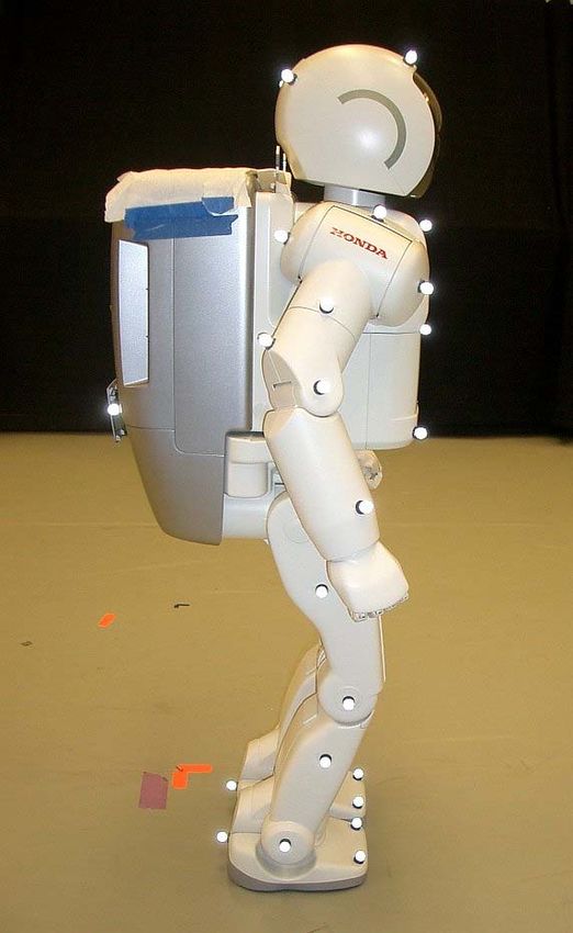
Fig. 1. The Honda ASIMO Humanoid robot at Carnegie Mellon. Side
Index Terms— Humanoid robots, footstep planning, biped view of the 120 cm tall robot (left); ASIMO navigating using footstep
locomotion, obstacle avoidance planning to avoid obstacles on the floor (right).
I. I NTRODUCTION
The design of algorithms to compute robust goal-directed the time allowed. The current implementation allows us to
navigation strategies for biped humanoid robots is an im- compute footstep plans of up to 20-30 steps in one second
portant area of research. For complex indoor environments on typical PC hardware.
designed for humans, this includes dealing with furniture, The rest of the paper is organized as follows: Section II
walls, stairs, doors, and previously unknown obstacles gives an overview of related research, Section III describes
on the floor. For outdoor environments, this includes the our biped stepping model and the planning algorithm,
ability to navigate on rough terrain and uneven surfaces. Section IV analyzes results from an online implementa-
Because legged robots have the ability to step over and tion using the Honda ASIMO humanoid robot (Figure 1)
onto obstacles in their path, they are uniquely suited to traversing known environments, and Section V concludes
overcoming these difficulties. However, existing navigation with a summary and directions for future research.
planning methods fail to consider these additional capabil-
ities, because they were primarily designed for wheeled II. BACKGROUND
mobile robots. Global path planning and obstacle avoidance strategies
We approach the problem of computing global naviga- for mobile robots and manipulators have a large and
tion strategies for biped humanoids as one involving an iter- extensive history in the robotics literature (e.g. see [1], [2]
ated discrete search over a set of valid foot placements. The for an overview of early work). Global navigation strategies
result of the computation is a sequence of footstep place- for mobile robots can usually be obtained by searching
ments that reach a goal region while minimizing encoded for a collision-free path in a 2D environment. Because of
heuristics for effort, risk, or the number and complexity the low-dimensionality of the search space, very efficient
of the steps taken. As with other large search domains, and complete (or resolution-complete) algorithms can be
computing true optimal solutions for biped navigation is employed [3]. These techniques can be partially applied
computationally intractable. The challenge then becomes to biped humanoid robots. Conservative global navigation
to exploit problem structure and design efficient cost met- strategies can be obtained by choosing an appropriate
rics and heuristics that improve search performance. For bounding volume (e.g. a cylinder), and designing locomo-
systems with sensing uncertainty and modeling errors in tion gaits for following navigation trajectories computed
addition to obstacles in dynamic environments, footstep by a 2D path planner [4], [5]. However, this always forces
planning algorithms must be fast enough for real-time the robot to circumvent obstacles. In contrast, legged robots
replanning. Our approach uses a limited-horizon search such as biped humanoids have the unique ability to traverse
that computes the best partial footstep path it can find in obstacles by stepping over or onto them.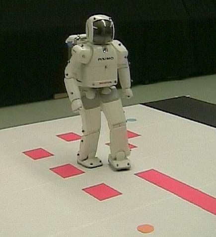
Since reliable, walking biped robots have been de-
veloped only recently, much less research attention has
been focused on developing complete global navigation
strategies for biped robots. Most research has focused on
pre-generating stable walking trajectories (e.g. [6]–[8]), or
on dynamic balance and control (e.g. [9], [10]). Recently,
techniques have been developed to generate stable walking
trajectories online [11], [12], though these results do not
account for obstacles. For quadruped robots, adaptive gait
generation and control on irregular terrain and among
obstacles has been previously studied [13]. This method
has not yet been applied to biped robots. Sensor-based
obstacle-avoidance techniques have been developed for           Fig. 2. State dependence of the effects of the actions. The black blocks
bipeds navigating in unknown environments [14], [15].           represent the location of the right foot, and the rectangles are the resulting
                                                                locations of the left foot from each commanded action. The commands
However, such reactive methods can become trapped in lo-        given to the robot are not shown. Left: Effects of commanded actions
cal loops or dead-ends, because they do not consider global     from standing still. Right: Effects of commanded actions from full speed
information. In biomechanics, researchers have studied          walking.
the problem of how humans perform local planning over
irregular terrain based on visual feedback [16], [17]. Other
related techniques in computer animation that use footprint     actions that causes the robot to walk to the goal location,
placement for motion specification have been developed          while not colliding with obstacles, or stepping into any
for bipeds [18], [19], and quadrupeds [20], [21]. Large         unsafe or unstable locations. Legged robots have the unique
datasets of captured human motion are now available, and        ability to step onto or over obstacles or unsafe footholds,
techniques have been developed to synthesize animations         which can allow them to traverse terrains that would be
based on artist specified goals and automatically computed      impassable to a wheeled mobile robot.
motion transitions [22].                                           To solve this problem, we utilize a high-level planner that
   Early work on footstep planning for bipeds involved gen-     ignores as much of the underlying details of leg movement
erating statically stable stepping sequences for a simulated    and trajectory generation as possible, and works instead
humanoid in cluttered environments [23]. This approach          from a description of the robot’s capabilities. It plans at
was extended to handle complex height maps, uneven              the level of footsteps, and returns a sequence of footholds
terrain, and allow stepping motions that are not statically     that the robot can reach carrying it from the initial to the
stable [24]. Another planner that also uses heightmaps,         goal location.
but generates stepping motions for a simulated world is         A. Biped Model
described in [25]. For our planner, the most complex
examples still run only in simulation, but we have created         In our previous work [23], [24], [26], we could describe
a simplified online version of the planner that is fast         the capabilities of the robot purely by the locations the
enough for continuous replanning on the H7 humanoid             swing foot could reach relative to the stance foot. We could
robot platform [24], [26]. For the experiments in this          provide a list of footstep locations to the controller running
paper, we used Honda’s ASIMO humanoid robot [27], and           on the robot H7, and it would compute a walking trajectory
developed a state-dependent footstep action mapping to          to step on those footholds. With the level of control we
compute footstep plans in time-varying environments with        have been provided for ASIMO, we cannot specify foot
predictable moving obstacles.                                   location directly. Instead, we specify a desired displacement
   In the path planning literature, related approaches using    of the body. As part of ASIMO’s balance control, the actual
classical AI search or dynamic programming (see [28],           footsteps the robot takes for a given command varies based
[29]) have been applied to finding collision-free motions.      on the state of the robot. For example, if told to stop while
Some examples include car-like robots [30], kinodynamic         walking quickly forward, it will not stop immediately,
planning [31], calculating sequences of pushing motions         but take one more small step forward in slowing down.
[32], planning for constrained systems [33], optimal control    Because our commanded actions may be modified by the
of manipulators [34], [35], and a variety of planning           state of the robot, our planner must take the state of the
problems in a game-theoretic framework [36]. Ultimately,        robot into account while planning a sequence of actions.
planning problems in robotics can be cast as discrete           Figure 2 shows an example of how the effects of actions
heuristic search problems involving cost metrics, sets of       are modified by the robot’s current state.
candidate actions, and goal regions.                               Let S be the set of all possible states of the robot,
                                                                including its joint positions, velocities, and world posi-
               III. F OOTSTEP P LANNING                         tion and velocity. Without this state dependence, the only
  For a biped robot, given a start location, a goal location,   information the footstep planner needs is a projection of
and an obstacle-filled environment in which footsteps must      the state, L , the set of stance foot locations. Let A be
be chosen carefully, we wish to find an optimal sequence of     the set of possible actions that can be commanded to the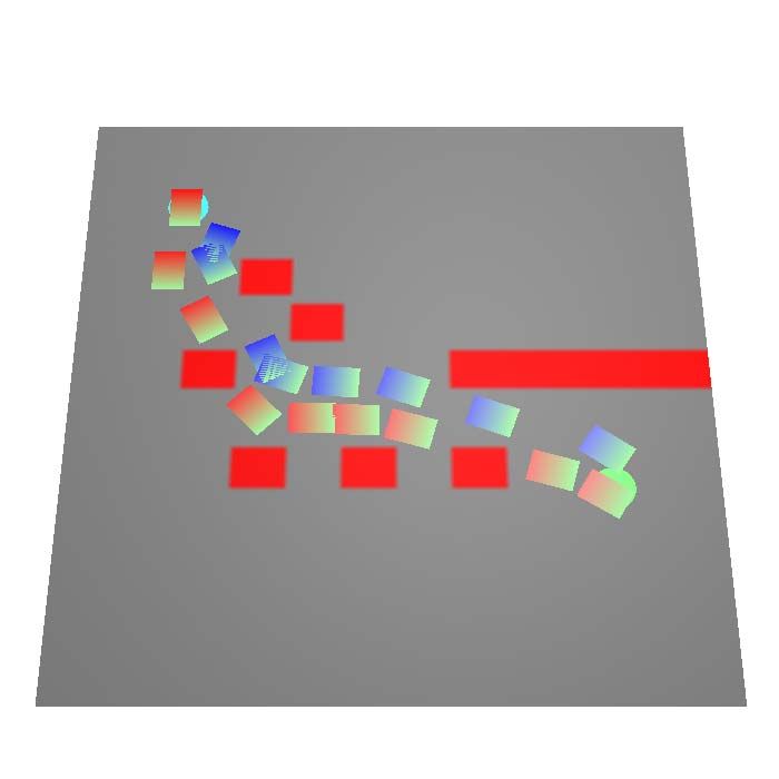
robot. To determine the result of state-dependent actions,        Algorithm 1: P LAN PATH(sinit , sgoal , F, T, E)
the full state of the robot, s ∈ S , is needed, as well as the
environment, e ∈ E , where E is the set of environments. In              //Initialize search (state, cost, expected, parent);
addition, the planner needs the mapping T : S × A × E → S .       1     Q.Insert(sinit , 0, 0, NULL);
With this mapping, the planner can string sequences of            2     while running time < tmax do
actions together, and know what the resulting state will be       3        sbest ← Q.ExtractMin();
after each action.                                                4        if GoalReached(sbest ,sgoal ) then
   For ASIMO, we do not have access to the full state             5             return sbest ;
information. However, we know the history of commands                      end
we have given to the robot. By measuring the robot’s              6         e ← E(sbest .time);
response to sequences of commands, we found that the              7        A ← F(sbest , e);
state of the robot at step i can be sufficiently described for    8        foreach a ∈ A do
this mapping by the current stance foot location, li ∈ L , and    9             snext ← T (sbest , a, e);
the last two commanded actions, ai−2 , ai−1 ∈ A . Therefore,      10            cl ← LocationCost(e, snext );
we can construct an alternate version of T to take us from        11            cs ← StepCost(e, a);
step i to step i + 1, using the information available to us       12            ce ← ExpectedCost(e, snext );
(commanded actions) to find the information the planner           13            Q.Insert(snext , sbest .cost + cl + cs , ce , sbest );
                                                                           end
needs (footstep locations): TASIMO : A × A × L × E × A →               end
L.
             TASIMO (ai−2 , ai−1 , li , ei+1 , ai ) = li+1
   We created this mapping by having ASIMO perform se-               For dynamic environments, the information value, i, may
quences of commands, and recording the resulting motion.          vary with time. A moving obstacle will differ in the cells
The motion was captured using the Vicon1 optical system.          it makes impassable at different times.
Twelve cameras were used, and each one captures data
with a frequency of 120 Hz and a resolution of 1000 x
                                                                  C. Planning Algorithm
1000. Six markers were placed on the robot’s feet. From
the positions of these markers, we determined the positions          1) Overview: The planner takes as input an environ-
and orientations of both the left and right feet. We can          ment, an initial and goal state sinit and sgoal , a mapping F
then compute the relative displacements of the feet from          to find possible actions that may be taken, and a mapping
this data. We chose a set of seven actions for each foot,         T to calculate action effects. If a path is found the planner
and with the displacements dependent on the previous two          returns the solution as an ordered list of the actions that
actions, we captured 343 sequences of commands to cover           should be commanded to reach the goal.
all possibilities. Parsing this data gave us TASIMO for the          For ASIMO, F returns a set of leg-specific actions based
seven selected actions. This information can then be used         on which leg was the stance leg. T provides the transform
as a lookup table during planning.                                from the stance foot location to the next stance location,
   An additional dependency on the state and the environ-         based on the motion capture data.
ment can be the set of available actions, A . Certain actions,       2) A* Search: The search through sequences of actions
such as making a step with a specific foot or operating a         is performed by an A* search, shown in Algorithm 1.
light switch, may only be applicable in specific states of        The planner continues searching the space until it finds
the robot and specific conditions in the environment. To          a path to the goal or exceeds a specified time. Three cost
resolve this dependency, the planner needs the mapping            functions are used to compute the cost of each node to be
F : S × E → A to compute the available action set.                inserted into the queue. The first cost is the location cost,
B. Environment Model                                              which evaluates the footstep location with regard to the
                                                                  environment to determine if that location is a safe place to
   The environment is represented by a grid of cells. Each
                                                                  step. The second cost is the step cost, which calculates the
cell c is represented by (x, y, i) ∈ ℜ2 × {0, 1}, where (x, y)
                                                                  cost to the robot to make the desired step. This weighting
is its location in the grid, and i an information value about
                                                                  is used to prefer certain actions over others. The final
whether the terrain is valid or not. Together, the cells create
                                                                  cost is the estimated remaining cost-to-go. This cost is
a bitmap representing the free spaces and obstacles of the
                                                                  calculated by planning backwards from the goal with a
terrain the planner must overcome. This map of the terrain
                                                                  standard mobile robot planner as a precomputation step. As
can be generated from sensor data or built from models of
                                                                  the planner explores outward from the goal, it records the
the environment. For this work we did not include height
                                                                  cost to reach each location. This cost provides an informed
data in the terrain representation. The level of control we
                                                                  estimate of the actual cost, and is useful for avoiding local
have for commanding ASIMO does not include modifying
                                                                  minimums. However, it is not an admissible heuristic, as
the swing leg trajectory, so we are limited to flat obstacles,
                                                                  it can vastly overestimate the cost in some situations [37].
or negative obstacles (holes in the floor).
                                                                  This choice means that we sacrifice optimality guarantees
  1 Vicon   is a trademark of Vicon Motion Systems, Ltd.          for execution speed when using this heuristic.
by a colored rectangle. The circles in the environment
represent the start and goal locations for the robot. We
tested different scenarios where we varied the robot’s start
and goal positions. In each case, the planner successfully
returns a set of commands that allow the robot to move
from the start to the goal while avoiding the obstacles. One
set of start and goal locations is shown in Figure 3, along
with the path returned by the planner. Figure 4 shows an
example of the robot executing this path.
Notice that the plans allow the robot to step over the
obstacles, utilizing its biped capabilities.
C. Dynamic Obstacles
Figure 5 shows an environment with predictable dynamic
obstacles. There are two rows of colored rectangles repre-
senting the moving obstacles. Each row of obstacles are
attached to strings that are then attached to an electric
motor. The strings are also represented in the environment
Fig. 3. Plan generated for a static environment. The start location is in the as places upon which the robot cannot step. There are two
upper left. The solid red regions are obstacles. Blue footprints correspond motors, each of which pulls the strings to one side, thereby
to footprints for the left foot, while reddish footprints correspond to those moving the obstacles. The two rows of obstacles have
of the right foot.
regular spacings between the blocks, although the spacing
is different for each row. The first row moves at 0.1 meters
3) Predictable Dynamic Environments: If the environ- per second, and the second row moves at 0.18 meters per
ment will change in predictable ways, these changes can second.
be planned for with surprisingly few modifications to the In this environment, the standard mobile robot planner
original algorithm. Time must be included in the state of fails, as the start and goal are in disconnected areas of
the robot, s ∈ S , and updated with the time required to the environment. The ability of the robot to step over the
execute various actions. This requirement means that the strings connecting the blocks enables it to reach the goal
mapping T must correctly handle the time component of location.
the state when mapping to a new state. To extend TASIMO , In our example, the robot successfully steps through
we were able to extract the time required for each action the dynamic obstacles. It is interesting to note that when
for each state from the same data that gave us the original passing through the second row of obstacles, the robot
mapping. Finally, instead of taking an environment as input, sidesteps to wait for an obstacle to move past before
the planner takes the function E : T → E to acquire the stepping through them.
environment specific to the desired time (shown in Line 6
V. C ONCLUSION
of Algorithm 1), where T is the set of possible times.
In our implementation, we constructed a set of cell grids, We have presented a footstep planner for the Honda
each with an associated time. During execution, the planner ASIMO humanoid robot that computes metric-optimal se-
would use the map with the closest time to the desired time. quences of footstep positions to navigate toward a goal
Also, for these environments, a straight Euclidean distance location while avoiding both static obstacles and obstacles
metric was used to estimate the remaining cost, instead of moving along predictable trajectories. The set of possible
the mobile robot planner. future foot placement positions are dependent on the cur-
rent state of the robot. Using a finite set of state-dependent
IV. E XPERIMENTAL R ESULTS actions, we use an A* search to compute optimal sequences
A. Experimental Setup of footstep locations up to a time-limited planning horizon.
Each of the following experiments were performed on We present experimental results demonstrating the robot
the Honda ASIMO robot [27]. The tests were performed navigating through both static and dynamic environments
on a hard flat surface in an area three meters on each side. that include obstacles moving on predictable trajectories.
The terrain representation used cells that were 0.025 meters Future work includes incorporating visual feedback on
per side. The environments and start and goal locations the ASIMO to enable real-time replanning in dynamic
were provided to the planner, and the robot executed the environments.
commands dictated by the planner’s result.
ACKNOWLEDGMENTS
B. Static Obstacles We thank Honda Motor Corporation for generously pro-
An environment with static obstacles were built on viding the ASIMO humanoid robot hardware to Carnegie
the hard flat surface. Each static obstacle is represented Mellon University for these experiments. This research wasFig. 4. ASIMO navigating in an environment with static obstacles.
partially supported by NSF grants ECS-0325383, ECS- [9] M. Vukobratovic, B. Borovac, D. Surla, and D. Stokic, Biped
0326095, and ANI-0224419. Partial support for the 3rd Locomotion: Dynamics, Stability, Control, and Applications. Berlin:
Springer-Verlag, 1990.
author was provided by NSF CNS-0203912. [10] J. Pratt and G. Pratt, “Exploiting natural dynamics in the control
of a 3d bipedal walking simulation,” in In Proc. of Int. Conf. on
R EFERENCES Climbing and Walking Robots (CLAWAR99), Sept. 1999.
[11] K. Nishiwaki, T. Sugihara, S. KAGAMI, M. Inaba, and H. Inoue,
[1] J. C. Latombe, Robot Motion Planning. Boston, MA: Kluwer “Online mixture and connection of basic motions for humanoid
Academic Publishers, 1991. walking control by footprint specification,” in Proc. IEEE Int’l Conf.
[2] Y. K. Hwang and N. Ahuja, “A potential field approach to path on Robotics and Automation (ICRA’01), Seoul, Korea, May 2001.
planning,” IEEE Trans. Robot. & Autom., vol. 8, no. 1, pp. 23–32, [12] K. Nishiwaki, S. Kagami, Y. Kuniyoshi, M. Inaba, and H. Inoue,
Feb. 1992. “Online generation of humanoid walking motion based on a fast
[3] A. Stentz, “Optimal and efficient path planning for partially-known generation method of motion pattern that follows desired zmp,”
environments,” in Proc. IEEE Int’l Conf. on Robotics and Automa- in Proc. IEEE/RSJ Int. Conf. on Intelligent Robots and Systems
tion (ICRA’94), 1994, pp. 3310–3317. (IROS’02), 2002, pp. 96–101.
[4] J. Kuffner, “Goal-directed navigation for animated characters using [13] S. Hirose, “A study of design and control of a quadruped walking
real-time path planning and control,” in Proc. CAPTECH ’98 : vehicle,” Int. J. Robotics Research., vol. 3, no. 2, pp. 113–133,
Workshop on Modelling and Motion Capture Techniques for Virtual Summer 1984.
Environments, 1998, pp. 171–186. [14] M. Yagi and V. Lumelsky, “Biped robot locomotion in scenes with
[5] J. Pettre, J.-P. Laumond, and T. Simeon, “A 2-stages locomotion unknown obstacles,” in Proc. IEEE Int’l Conf. on Robotics and
planner for digital actors,” in Proc. SIGGRAPH Symp. on Computer Automation (ICRA’99), Detroit, MI, May 1999, pp. 375–380.
Animation, 2003. [15] O. Lorch, J. Denk, J. F. Seara, M. Buss, F. Freyberger, and
[6] K. Hirai, M. Hirose, Y. Haikawa, and T. Takenaka, “The devel- G. Schmidt, “ViGWaM - an emulation environment for a vision
opment of honda humanoid robot,” in Proc. IEEE Int’l Conf. on guided virtual walking machine,” in Proc. IEEE Int. Conf. on
Robotics and Automation (ICRA’98), May 1998, pp. 1321–1326. Humanoid Robotics (Humanoids 2000), 2000.
[7] J. Yamaguchi, S. Inoue, D. Nishino, and A. Takanishi, “Development [16] A. Patla, A. Adkin, C. Martin, R. Holden, and S. Prentice, “Char-
of a bipedal humanoid robot having antagonistic driven joints and acteristics of voluntary visual sampling of the environment for safe
three dof trunk,” in Proc. IEEE/RSJ Int. Conf. on Intelligent Robots locomotion over different terrains,” Exp. Brain Res., vol. 112, pp.
and Systems (IROS’98), 1998, pp. 96–101. 513–522, 1996.
[8] K. Nagasaka, M. Inaba, and H. Inoue, “Walking pattern generation [17] A. Patla, E. Niechwiej, and L. Santos, “Local path planning during
for a humanoid robot based on optimal gradient method,” in Proc. human locomotion over irregular terrain,” in Proc. AMAM2000,
IEEE Int. Conf. on Systems, Man, and Cybernetics, 1999. 2000.Fig. 5. Example with dynamic obstacles. The obstacles on the floor are moving to the camera’s right at differing speeds, forcing the robot to carefully
time its steps through the environment.
[18] M. Girard, “Interactive design of computer-animated legged animal [28] R. E. Bellman, Dynamic Programming. Princeton, New Jersey:
motion,” IEEE Computer Graphics & Applications, vol. 7, no. 6, Princeton University Press, 1957.
pp. 39–51, June 1987. [29] R. Korf, “Artificial intelligence search algorithms,” in CRC Hand-
[19] M. van de Panne, “From footprints to animation,” in Proc. Computer book of Algorithms and Theory of Computation, M. Atallah, Ed.
Graphics Forum, vol. 16, no. 4, Oct. 1997, pp. 211–223. Boca Raton, FL: CRC Press, 1998, pp. 36.1–20.
[20] E. Kokkevis, D. Metaxas, and N. I. Badler, “Autonomous animation [30] J. Barraquand and J. Latombe, “Nonholonomic multibody mobile
and control of four-legged animals,” in Proc. Graphics Interface, robots: Controllability and motion planning in the presence of
May 1995, pp. 10–17, iSBN 0-9695338-4-5. obstacles,” Algorithmica, vol. 10, pp. 121–155, 1993.
[31] B. Donald, P. Xavier, J. Canny, and J. Reif, “Kinodynamic motion
[21] N. Torkos and M. van de Panne, “Footprint-based quadruped motion
planning,” Journal of the ACM, vol. 40, no. 5, pp. 1048–1066, Nov.
synthesis,” in Proc. Graphics Interface, 1998, pp. 151–160.
1993.
[22] J. Lee, J. Chai, P. S. A. Reitsma, J. K. Hodgins, and N. S. Pollard, [32] K. M. Lynch and M. T. Mason, “Stable pushing: Mechanics,
“Interactive control of avatars animated with human motion data,” controllability, and planning,” Int. J. Robotics Research., vol. 15,
ACM Trans. on Graphics, vol. 21, no. 3, pp. 491–500, 2002. no. 6, pp. 533–556, Dec. 1996.
[23] J. Kuffner, K. Nishiwaki, S. Kagami, M. Inaba, and H. Inoue, [33] J. Barraquand and P. Ferbach, “Path planning through variational
“Footstep planning among obstacles for biped robots,” in Proc. dynamic programming,” Digital - PRL Research Report, Tech.
IEEE/RSJ Int. Conf. on Intelligent Robots and Systems (IROS’01), Rep. 33, sep 1993.
2001, pp. 500–505. [34] J. Bobrow, S. Dubowsky, and J. Gibson, “Time-optimal control of
[24] J. Chestnutt, J. Kuffner, K. Nishiwaki, and S. Kagami, “Planning robotic manipulators,” Int. Journal of Robotics Research, vol. 4,
biped navigation strategies in complex environments,” in Proc. no. 3, 1985.
IEEE-RAS/RSJ Int. Conf. on Humanoid Robots (Humanoids’03), [35] Z. Shiller and S. Dubowsky, “On computing time-optimal motions
Munich, Germany, Oct. 2003. of robotic manipulators in the presence of obstacles,” IEEE Trans.
[25] T.-Y. Li, P.-F. Chen, and P.-Z. Huang, “Motion planning for hu- on Robotics and Automation, vol. 7, no. 7, Dec. 1991.
manoid walking in a layered environment,” in Proc. IEEE Int. Conf. [36] S. M. LaValle, “A game-theoretic framework for robot motion
on Robotics and Automationd Systems (ICRA’03), 2003. planning,” Ph.D. dissertation, University of Illinois, Urbana, IL, July
[26] J. Kuffner, K. Nishiwaki, S. Kagami, Y. Kuniyoshi, M. Inaba, and 1995.
H. Inoue, “Online footstep planning for humanoid robots,” in Proc. [37] J. Chestnutt and J. Kuffner, “A tiered planning strategy for biped
IEEE Int’l Conf. on Robotics and Automation (ICRA’2003), 2003. navigation,” in Proc. IEEE-RAS/RSJ Int. Conf. on Humanoid Robots
[27] Y. Sakagami, R. Watanabe, C. Aoyama, S. Matsunaga, N. Higaki, (Humanoids’04), Santa Monica, California, Nov. 2004.
and K. Fujimura, “The intelligent asimo: System overview and
integration,” in Proc. IEEE/RSJ Int. Conf. on Intelligent Robots and
Systems (IROS’02), 2002, pp. 2478–2483.You can also read