Fuel Fabrication Capability Research and Development Plan - Global Threat Reduction Initiative - Convert Program June 2013 - PNNL
←
→
Page content transcription
If your browser does not render page correctly, please read the page content below
PNNL-22528

Fuel Fabrication
Capability Research and
Development Plan
Global Threat Reduction Initiative –
Convert Program
June 2013

DJ Senor    D Burkes

            Prepared for the U.S. Department of Energy
            under Contract DE-AC05-76RL01830
PNNL-22528

Fuel Fabrication Capability
Research and Development Plan

DJ Senor             D Burkes

June 2013

Prepared for
the U.S. Department of Energy
under Contract DE-AC05-76RL01830

Pacific Northwest National Laboratory
Richland, Washington 99352

Summary

    The purpose of this document is to provide a comprehensive review of the mission of the Fuel
Fabrication Capability (FFC) within the Global Threat Reduction Initiative Convert Program, along with
research and development (R&D) needs that have been identified as necessary to ensuring mission
success. The design and fabrication of successful nuclear fuels must be closely linked endeavors.
Therefore, the overriding motivation behind the FFC R&D program described in this plan is to foster
closer integration between fuel design and fabrication to reduce programmatic risk by ensuring the
following:
 • The manufacturing process consistently produces fuel with acceptable quality (i.e., meets or exceeds
   design requirements)
 • The sensitivity of material properties and characteristics to manufacturing process parameters is
   clearly understood so adequate process specifications can be defined
 • Fuel product specifications are realistic and achievable using the selected manufacturing methods
 • A better linkage between the effect of process parameters on fuel performance, to ensure that changes
   or variability in manufacturing does not have an adverse effect on irradiation behavior

    These motivating factors are all interrelated, and progress addressing one will aid understanding of
the others. The FFC R&D needs fall into two principle categories, 1) baseline process optimization, to
refine the existing fabrication technologies, and 2) manufacturing process alternatives, to evaluate new
fabrication technologies that could provide improvements in quality, repeatability, or cost. The FFC
R&D Plan examines efforts currently under way in regard to coupon, foil, plate, and fuel element
manufacturing, and provides recommendations for a number of R&D topics that are of high priority but
not currently funded (i.e., knowledge gaps). The plan ties all FFC R&D efforts into a unified vision that
supports the overall Convert Program schedule in general, and the fabrication schedule leading up to the
MP-1, MP-2, and FSP-1 irradiation experiments specifically.

    The FFC R&D Plan describes the downselection methodology for optimizing the baseline fabrication
process as well as considering alternative manufacturing technologies. The criteria for downselection
include the following considerations:
 • Technical Merit – Does the process produce parts that meet product specification requirements?
 • Reproducibility – Does the process consistently produce high-quality parts?
 • Economics – Does the process offer life-cycle (not just capital) cost savings over the baseline process,
   including considerations of efficient use of uranium feedstock and scrap recycle??
 • Scaling – Does the process scale to full prototypic part dimensions?
 • Throughput – Does the process lend itself to high-volume throughput without sacrificing its
   advantages?
 • Quality Assurance – Does the process lend itself to implementation in an NQA-1 manufacturing
   environment?

                                                    iii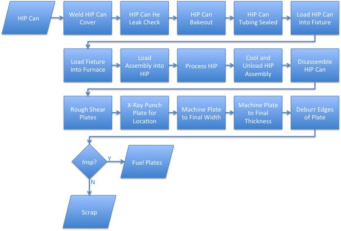
• Environment, Safety, and Health – Can the process be implemented effectively in a uranium
   production facility regulated by the U.S. Department of Energy and/or the Nuclear Regulatory
   Commission?
 • Schedule – Can the process be developed and implemented in time to meet the Convert Program
   schedule for fuel down-selection?

     The fabrication technology decision gates and downselection logic and schedules are tied to the
schedule for fabricating the MP-1 fuel plates, which will provide the necessary data to make a final fuel
fabrication process downselection. Because of the short turnaround between MP-1 and the follow-on
MP-2 and FSP-1 experiments, the suite of specimen types that will be available for MP-1 will be the same
as those available for MP-2 and FSP-1. Therefore, the only opportunity to explore parameter space and
alternative processing is between now and 2016 when the candidate processes are down-selected in
preparation for the MP-1, MP-2, and FSP-1 plate manufacturing campaigns. A number of key risks
identified by the FFC are discussed in this plan, with recommended mitigating actions for those activities
within FFC, and identification of risks that are impacted by activities in other areas of the Convert
Program.

    The intent is for this R&D Plan to be a living document that will be reviewed and updated on a
regular basis (e.g., annually) to ensure that FFC R&D activities remain properly aligned to the needs of
the Convert Program. The R&D Plan does not include discussion of FFC initiatives related to
production-scale manufacturing of fuel (e.g., establishment of the Pilot Line Production Facility), rather,
the goal of this plan is to document the research and development activities needed ultimately to enable
high-quality and cost-effective production of the fuel by the commercial fuel fabricator.

                                                     iv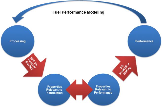
Acronyms and Abbreviations

ATR          Advanced Test Reactor
ATR-C        ATR critical assembly
B&W          Babcock & Wilcox
DOE          U.S. Department of Energy
DU           depleted uranium
DU-Mo        depleted uranium-molybdenum
EBSD         electron backscatter diffraction
EDS          energy dispersive spectroscopy
EPJ          electromagnetic pulse joining
ESD          electro-spark deposition
EU           enriched uranium
FD           fuel development
FFC          fuel fabrication capability
FLA-ICP-MS   femtosecond laser ablation inductively-coupled plasma mass spectrometry
FY           fiscal year
GTRI         Global Threat Reduction Initiative
HEU          highly enriched uranium
HFIR         High Flux Isotope Reactor
HIP          hot isostatic press
HPRR         high performance research reactor
ICP-MS       inductively-coupled plasma mass spectrometry
ICP-OES      inductively-coupled plasma optical emission spectrometry
INL          Idaho National Laboratory
LEU          low enriched uranium
LEU-Mo       low enriched uranium-molybdenum
MAQP         Manufacturing and Quality Plan
MITR         Massachusetts Institute of Technology Reactor
Mo           molybdenum
MURR         Missouri University Research Reactor
NNSA         National Nuclear Security Administration
PM           powder metallurgy
PNNL         Pacific Northwest National Laboratory
PVD          physical vapor deposition
QA           quality assurance
QRL          quality rigor level
R&D          research and development

                                           v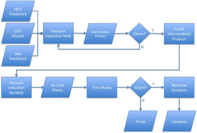
RC      reactor conversion
RERTR   Reduced Enrichment Research and Test Reactor
SEM     scanning electron microscopy
U-Mo    uranium-molybdenum
UMoF    uranium-molybdenum feedstock
UPF     Uranium Processing Facility
UT      ultrasonic testing
VAR     vacuum arc remelting
VIM     vacuum induction melting
WBS     work breakdown structure
XRF     x-ray fluorescence

                                      vi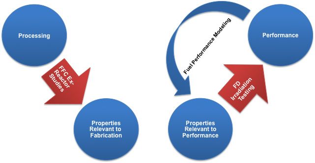
Contents
Summary ...............................................................................................................................................    iii
Acronyms and Abbreviations ...............................................................................................................                  v
1.0 Introduction ..................................................................................................................................       1.1
       1.1 Mission of the GTRI Convert Program ................................................................................                           1.1
       1.2 Role of the Fuel Fabrication Capability ...............................................................................                        1.2
       1.3 Fuel Fabrication Process Development to Date ...................................................................                               1.3
2.0 Motivation and Objectives of FFC Research and Development ..................................................                                          2.1
       2.1 Lack of a Well-defined, Repeatable Process ........................................................................                            2.1
       2.2 Uncertain Relationship Between Process Parameters and Material Characteristics ............                                                    2.1
       2.3 Need for Clearly-Defined and Value-added Product Specifications ....................................                                           2.2
    2.4 Relationship between FFC and FD Research and Development Plans ................................                                                   2.2
3.0 Coupon Manufacturing Research and Development ....................................................................                                    3.1
       3.1 Coupon Baseline Process Optimization ...............................................................................                           3.2
               3.1.1 Molybdenum Feedstock Form...................................................................................                         3.2
               3.1.2 Mold Geometry .........................................................................................................              3.3
               3.1.3 Post-casting Homogenization ....................................................................................                     3.3
               3.1.4 Post-casting Quench ..................................................................................................               3.4
               3.1.5 Multiple Coupon Casting ..........................................................................................                   3.5
               3.1.6 Separate Alloying and Downblending ......................................................................                            3.6
               3.1.7 Master DU-Mo Alloy Casting Parameters ................................................................                               3.7
               3.1.8 Coupon Machining ....................................................................................................                3.7
               3.1.9 Rolling Process Modeling .........................................................................................                   3.9
               3.1.10 Interrupted Rolling ....................................................................................................            3.9
               3.1.11 Scrap Recycle ............................................................................................................          3.9
               3.1.12 Microwave Melting ................................................................................................... 3.10
       3.2 Coupon Process Alternatives ............................................................................................... 3.10
               3.2.1 Billet Casting ............................................................................................................. 3.11
               3.2.2 Billet Rolling ............................................................................................................. 3.11
               3.2.3 Powder Metallurgy Coupon Fabrication ................................................................... 3.12
4.0 Foil Manufacturing Research and Development ..........................................................................                                4.1
       4.1 Foil Baseline Process Optimization .....................................................................................                       4.2
               4.1.1 Hot Rolling Reduction ..............................................................................................                 4.2
               4.1.2 Cold Rolling Reduction .............................................................................................                 4.4
               4.1.3 Rolling of Separately-alloyed and Downblended Foils.............................................                                     4.5
               4.1.4 Effect of Annealing Parameters on Foil Flatness ......................................................                               4.5
               4.1.5 Effect of Warm Rolling on Foil Flatness ..................................................................                           4.6
               4.1.6 Optimized Co-rolling Parameters..............................................................................                        4.6

                                                                              vii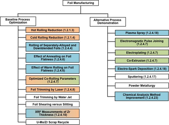
4.1.7 Foil Trimming by Laser ............................................................................................                 4.7
               4.1.8 Foil Trimming by Water Jet ......................................................................................                   4.7
               4.1.9 Foil Slitting................................................................................................................       4.7
               4.1.10 X-Ray Fluorescence Measurements of Zr Thickness................................................                                    4.8
           4.1.11 U-Mo/Zr Scrap Recycle Process Development.........................................................                                     4.8
       4.2 Foil Process Alternatives......................................................................................................               4.8
               4.2.1 Alternative Zr Application Methods .........................................................................                        4.9
               4.2.2 Chemical Analysis Method Improvement ................................................................. 4.12
5.0 Plate Manufacturing Research and Development.........................................................................                                5.1
       5.1 Plate Baseline Process Optimization ....................................................................................                      5.3
               5.1.1 Clad-to-Foil Thickness Ratio Effect on HIP .............................................................                            5.3
               5.1.2 Clad-to-Foil Thickness Ratio and Bend Radius Effects on Forming ........................                                            5.4
               5.1.3 HIP Can Optimization ...............................................................................................                5.5
               5.1.4 Can-Less HIP ............................................................................................................           5.6
               5.1.5 Plate Trimming by Laser ...........................................................................................                 5.6
               5.1.6 Inspection Methods to Improve Plate Machining Efficiency ....................................                                       5.7
               5.1.7 Machining with Time-saver ......................................................................................                    5.8
               5.1.8 Manufacturing Plates with Fins.................................................................................                     5.8
       5.2 Plate Process Alternatives ....................................................................................................               5.8
               5.2.1 Net-shape HIP Bonding ............................................................................................                  5.8
               5.2.2 Hot Pressing ..............................................................................................................         5.9
               5.2.3 Zr-Base Alloy Cladding ............................................................................................                 5.9
6.0 Element Manufacturing Research and Development ...................................................................                                   6.1
       6.1 Swaging Borated Side Plates................................................................................................                   6.1
       6.2 Welding Borated Side Plates ................................................................................................                  6.1
       6.3 Fuel Element Assembly with Zr-Base Alloy Cladding ........................................................                                    6.2
       6.4 Machining Element End Adapters .......................................................................................                        6.2
7.0 Cross-Cutting Research and Development Efforts .......................................................................                               7.1
    7.1 Source Material Availability ................................................................................................                    7.1
       7.2 Process Modeling .................................................................................................................            7.1
8.0 Other Considerations ....................................................................................................................            8.1
       8.1 Commercial Viability ...........................................................................................................              8.1
       8.2 Quality Assurance ................................................................................................................            8.2
       8.3 Schedule ...............................................................................................................................      8.2
9.0 Summary and Recommendations .................................................................................................                        9.1
       9.1 Decision Points.....................................................................................................................          9.1
       9.2 Knowledge Gaps ..................................................................................................................             9.3
       9.3 Risks .....................................................................................................................................   9.5
10.0 References .................................................................................................................................... 10.1

                                                                             viii
Figures
1.1 FFC Organizational Structure and Responsibilities ...................................................................... 1.4
2.1 Schematic Representation of the Ideal Relationships in the Understanding of Processing,
Properties, and Performance ......................................................................................................... 2.3
2.2 Schematic Representation of Current Relationships in the Understanding of Processing,
Properties, and Performance ......................................................................................................... 2.4
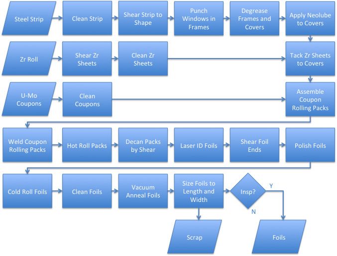
3.1 Simplified Flow Sheet for Baseline Coupon Manufacturing Process........................................... 3.1
3.2 FFC Coupon Manufacturing R&D Activities Described in Section 3.0 ....................................... 3.2
4.1 Simplified Flow Sheet for Baseline Foil Manufacturing Process ................................................. 4.1
4.2 FFC Foil Manufacturing R&D Activities Described in Section 4.0 ............................................. 4.2
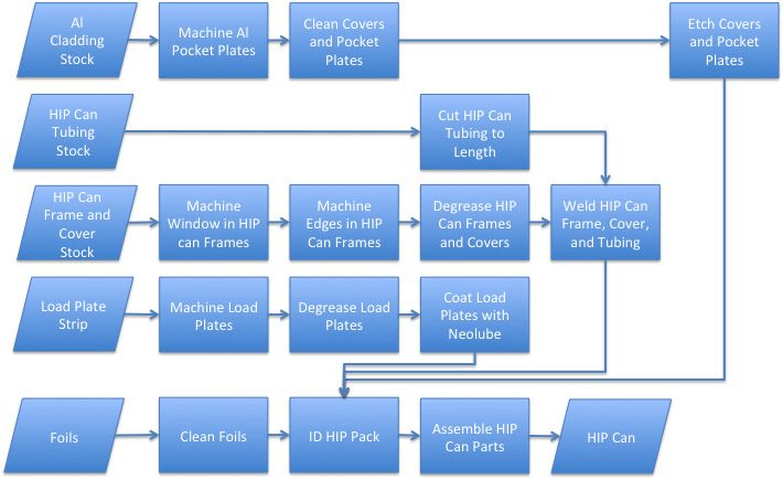
5.1 Simplified Flow Sheet for Baseline HIP Can Assembly Process ................................................. 5.1
5.2 Simplified Flow Sheet for Baseline Plate Manufacturing Process ............................................... 5.2
5.3 FFC Plate Manufacturing R&D Activities Described in Section 5.0 ........................................... 5.2
6.1 FFC Element Manufacturing R&D Activities Described in Section 6.0 ...................................... 6.1
7.1 Cross-cutting FFC R&D Activities Described in Section 7.0 ...................................................... 7.1
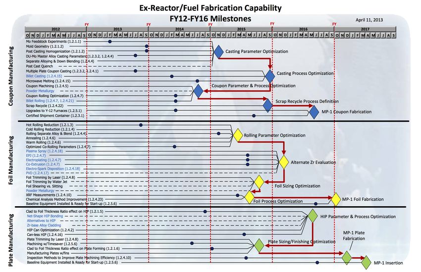
8.1 Convert Program Schedule Showing Key Fuel Down-selection Decision Points That Drive
Manufacturing Process Research and Development Needs .......................................................... 8.3
9.1 FFC Research and Development Down-selection Milestones Supporting the Overall Convert
Program Schedule ......................................................................................................................... 9.2
ixTables
9.1 Risks Related to FFC Work Scope ............................................................................................... 9.5
x1.0 Introduction
The purpose of this document is to provide a comprehensive review of the mission of the Fuel
Fabrication Capability (FFC) within the Global Threat Reduction Initiative (GTRI) Convert Program,
along with research and development (R&D) needs that have been identified as necessary to ensuring
mission success. In Section 1.0, the role of the FFC within the Convert Program is outlined, as are
relevant linkages to other aspects of the Program including Fuel Development (FD) and Reactor
Conversion (RC). The motivation behind each of the identified R&D needs and the objectives of the
R&D program is described in Section 2.0. Primary drivers include the need to 1) define a repeatable
manufacturing process, 2) relate process parameters to material properties and characteristics,
3) contribute to definition of the product and process specifications, and 4) integrate FFC and FD research
and development activities to focus on relevant characteristics and avoid duplication of effort.
Descriptions of the individual R&D activities planned to satisfy the objectives are included in
Sections 3.0, 4.0, 5.0 and 6.0 for coupon (uranium-molybdenum (U-Mo) fuel meat), foil (U-Mo fuel with
diffusion barrier), plate (clad fuel), and element (multiple plate assemblies) manufacturing process
development, respectively. Each of these four sections considers two principal categories of R&D,
1) baseline process optimization, to refine the existing fabrication technology, and 2) process alternatives,
to evaluate new fabrication technology that could provide improvements in quality, repeatability, or cost.
Section 7.0 describes a number of cross-cutting activities necessary for FFC to advance the state of the art
in fuel fabrication. Section 8.0 discusses other considerations associated with FFC R&D efforts,
including criteria for assessing commercial viability of manufacturing process, quality assurance, and
schedule. Section 9.0 describes the logic and schedule for critical decision points and their relationship to
manufacturing and process development needs, a listing of knowledge gaps that are not currently being
addressed within approved FFC scope, and a summary of risks that could impact FFC execution of the
R&D Plan. The intent is for this plan to be a living document that will be reviewed and updated on a
regular basis (e.g., annually) to ensure that FFC R&D activities remain properly aligned to the needs of
the Convert Program. The R&D Plan does not include FFC initiatives related to production-scale
manufacturing of fuel, rather, the goal of this plan is to document the research and development activities
needed to enable high-quality and cost-effective production of the fuel by the commercial fuel fabricator.
1.1 Mission of the GTRI Convert Program
Operating within the U.S. Department of Energy (DOE)/National Nuclear Security Administration
(NNSA), the GTRI mission is to reduce and protect vulnerable nuclear and radiological material located
at civilian sites worldwide. In order to achieve this mission, GTRI has three pillars that provide a
comprehensive approach to achieving this mission.
1. Convert research reactors and radioisotope production facilities from the use of highly enriched
uranium (HEU) to low enriched uranium (LEU) fuel
2. Remove and facilitate disposition of excess nuclear and radiological materials
3. Protect high priority nuclear and radiological materials from theft and sabotage
In support of the first pillar, the GTRI Reactor Conversion program (referred to in this document as
the Convert Program) works with civilian research and test reactors operating with HEU fuel around the
world. While NNSA provides enhanced physical protection systems at research and test reactors,
1.1converting the fuel used in these reactors to LEU permanently secures the site by removing the threat
posed by continued HEU operations. As the manufacture, shipment and storage of the HEU fuel for these
reactors can present an opportunity for terrorists to acquire the HEU they seek, eliminating the use of
HEU in civilian research and tests reactors by verifying the shutdown or conversion of these reactors to
an LEU-based fuel provides permanent threat reduction (NNSA 2013b).
A key component of the GTRI Convert Program is conversion from HEU to LEU of six U.S. high
performance research reactors (HPRRs) including the Advanced Test Reactor (ATR), the ATR critical
assembly (ATR-C), the High Flux Isotope Reactor (HFIR), the National Bureau of Standards Reactor, the
Missouri University Research Reactor (MURR), and the Massachusetts Institute of Technology Reactor
(MITR). The driver for conversion of these six reactors within the U.S. is to lead by example and
influence international reactor operators to convert to a fuel that is less attractive for proliferators from a
safeguards point of view, but effectively maintains the core mission and needs of the reactor. The scope
described in this document is associated with fabrication of the LEU fuel for the six U.S. HPRRs.
1.2 Role of the Fuel Fabrication Capability
The U.S. HPRR portion of the Convert Program consists of three principal activities, referred to as
pillars. These include FD, FFC, and RC. The overall objective of the FFC is to establish a cost-effective
and efficient manufacturing process that can be implemented by a commercial entity to provide LEU fuel
to the U.S. HPRRs after conversion from their existing HEU fuel. The baseline LEU fuel and fuel
fabrication process was developed by the FD pillar. It consists of a plate-type fuel with a monolithic U-
10Mo alloy foil bonded on two sides with a Zr diffusion barrier, and clad within an Al-base alloy.
Ultimately, the RC pillar will employ the commercial product developed by FFC in conversion of the
six U.S. HPRRs from their existing HEU fuel to the new LEU fuel.
Specifically, the FFC will:
• Transfer fabrication knowledge and processes to a commercial fuel fabricator
• Establish LEU manufacturing capability to support the conversion of the six U.S. HPRRs
• Demonstrate cost-effective and efficient production of developmental and production LEU fuel
• Procure initial reactor loadings to support conversion
• Fabricate demonstration and experiment fuel products as requested by the program
The scope described in this R&D Plan is necessary to ensure that FFC can meet these objectives on a
schedule and with product quality consistent with overall programmatic guidance. Technical challenges,
budget limitations, and schedule disruptions will increase the risk that the FFC objectives cannot be met
on the programmatic timeline described in Section 9.0. Further, it is important to note that this R&D Plan
does not address potential changes in the fuel manufacturing process to address irradiation performance
issues. Irradiation testing and fuel performance analysis are the responsibility of the FD pillar. If
irradiation testing or fuel performance modeling suggests that changes are needed to the fuel
manufacturing process, changes to the R&D program outlined in this plan will be required. Such changes
also have the potential to increase the risk that the FFC objectives cannot be met on the programmatic
timeline.
1.2The R&D activities described in this document are executed by a variety of organizations including
national laboratories, universities and commercial entities, as shown in Figure 1.1. Specifically, work is
currently being conducted at Los Alamos National Laboratory, Idaho National Laboratory (INL), Pacific
Northwest National Laboratory (PNNL), Y-12 National Security Complex, Georgia Institute of
Technology, Babcock & Wilcox (B&W) Nuclear Operations Group, Manufacturing Sciences
Corporation, Aerojet, and selected universities. While FFC management resides at PNNL, the FFC is not
a PNNL program. It is a national effort within the overall Convert Program. Accordingly, work is
apportioned based on considerations of technical capabilities, available capacity, and overall cost and
schedule. Thus, the division of work described in this document is an optimization of the available
resources to achieve the FFC objectives described above. If events warrant, scope may be moved from
one organization to another, and if new scope is warranted, particularly if it is outside the envelope of
current technologies, new organizations not currently involved may be approached to contribute.
1.3 Fuel Fabrication Process Development to Date
The five U.S. HPRRs and one critical assembly addressed by the Convert Program currently utilize
dispersion fuel consisting of HEU-containing particulate distributed throughout an Al-base alloy matrix.
The material form of the dispersion particulate varies, including UAlx for ATR and ATR-C (Gerstner
et al. 2010), MITR (Newton 2011), and MURR (Foyto et al. 2012), and U3O8 for HFIR (Primm et al.
2006) and National Bureau of Standards Reactor (Hanson and Diamond 2011). While dispersion fuel
forms, including U3Si2 and U-Mo alloy dispersions in an Al-base alloy matrix, have been demonstrated
for low power research reactors (Figure 1.1. FFC Organizational Structure and Responsibilities
The first irradiation experiments of U-10Mo monolithic fuel in a “mini-plate” configuration (1 in. x
4 in. x 0.055 in.) were conducted at ATR in 2005 under the Reduced Enrichment Research and Test
Reactor (RERTR) program. Seven insertions were conducted over the next few years as part of the
RERTR -6, -7A, -8, -9A, -9B, -10A, and -10B experiments at ATR. These were followed by irradiation
experiments starting in 2008 that included larger fuel plates (2.21 in. x 22.5 in. x 0.05 in.) and were
designated AFIP-2 and -3. These tests were conducted over a range of peak fuel temperatures, average
fission density, average fission rate, and average heat flux to evaluate the irradiation behavior of the fuel
over a variety of HPRR-relevant operating conditions. The tests evaluated irradiation performance of
alloy compositions ranging from 7 wt% to 12 wt% molybdenum (Mo), a range of fuel meat to cladding
thickness ratios, different foil configurations with and without diffusion barriers, Zr-base alloy cladding,
and a variety of fabrication methods. The fabrication methods were developed in a laboratory setting to
produce the RERTR- and AFIP-size plates and included variations in coupon reduction schedules,
different diffusion barrier materials and application methods, variations in foil reduction schedules, and
different fuel/cladding bonding methods. Based on the in-reactor and post-irradiation examination results
from these experiments, the baseline fuel form and associated baseline fuel fabrication processes were
identified (Robinson et al. 2009). The irradiation experiments conducted before the down-selection of the
final fuel form and fabrication processes did not include various HPRR-specific features such as cladding
fins, contoured fuel meat, or integral burnable absorbers. Subsequent irradiation experiments, including
RERTR-12 and AFIP-4, -6, -6 MKII, and -7 were conducted after the down-selection. Several of these
experiments experienced failures during irradiation; some were related to fuel performance while others
were not. In addition, certain irradiation performance issues such as low post-irradiation blister threshold
temperature were identified after the RERTR-12 and AFIP-4 experiments (PIE has not been conducted on
the AFIP-6, -6 MKII, or -7 experiments to date). Despite these issues, the baseline fuel form and
associated fabrication processes identified in Robinson et al. (2009) were provided to FFC for commercial
technology transfer and scale-up to prototypic dimensions and throughput.
1.4The FFC was initially created in 2007 to identify appropriate commercial entities for manufacturing
of U-10Mo monolithic fuel with prototypic dimensions and throughput (assuming conversion of all six
U.S. HPRRs using the same fuel form). This assessment was completed in 2009, and FFC then started
working toward transferring the fuel fabrication technology developed by FD at the laboratory scale to a
commercial manufacturer. Scoping studies were conducted to determine the feasibility of scaling the FD
fabrication process to appropriate size and throughput to produce the four key stages of the fuel: 1) U-
10Mo fuel meat (coupons), 2) Zr diffusion barrier application to the fuel meat (foils), 3) bonding of the
foils to the cladding (plates), and 4) assembly of plates into fuel elements. By 2011, the baseline
processes for producing the base fuel form was fully defined (Moore and Marshall 2010; Park et al. 2010)
and subsequent work focused on establishing a limited production facility to demonstrate prototypic-scale
manufacturing of the fuel. More recently, the need has become apparent for optimization of the baseline
processes as well as consideration of alternative processes where they offer potentially significant product
quality, cost, or throughput advantages. Consequently, FFC has embarked on an applied research and
development program to evaluate fabrication parameters and their effect on manufacturing efficiency and
product quality. In addition, FFC has started considering the work that will be necessary to fully define
acceptable manufacturing processes for “complex” fuel to include U.S. HPRR-specific features such as
fins, contoured fuel meat, and integral burnable absorbers. The current FFC R&D effort described by this
plan addresses optimization and alternatives for base fuel manufacturing, but includes only limited scope
focused on complex fuel manufacturing.
1.52.0 Motivation and Objectives of FFC Research and
Development
The overriding motivation for conducting the research and development activities described in this
plan is the need to ensure the following:
• The manufacturing process consistently produces fuel with acceptable quality (i.e., meets or exceeds
design requirements)
• The sensitivity of material properties and characteristics to manufacturing process parameters is
clearly understood so adequate process specifications can be defined
• Fuel product specifications are realistic and achievable using the selected manufacturing methods
• A better linkage between the effect of process parameters on fuel performance, to ensure that changes
or variability in manufacturing does not have an adverse effect on irradiation behavior
These motivating factors are all interrelated, and progress addressing one will aid understanding of
the others. The following sections expand on these motivating factors, define the specific objectives of
the FFC R&D program, and explain how the FFC R&D program will reduce overall programmatic risk in
these areas.
2.1 Lack of a Well-defined, Repeatable Process
Currently, the fuel fabrication process is poorly defined. While manufacturing methods have been
identified for each step in fuel fabrication, details associated with those processes have not been defined.
For example, cold rolling has been identified as the method of choice for reducing the coupons to the
desired thickness, primarily because of the ability to achieve specified dimensional tolerances (Meyer
et al. 2012). However, acceptable degrees of cold work have not been specifically defined, and a range
will likely be required due to differences in fuel-to-clad thickness ratios in plates for different reactors
(and between plates in the same fuel element for some of the reactors). In addition, there is evidence that
different microstructures can result for the same overall reduction depending on the specific reduction
schedule. Aggressive early reduction steps followed by more moderate reduction steps can produce a
different microstructure than a greater number of moderate reduction steps (Meyer et al. 2012). To ensure
a truly repeatable fabrication process that meets all applicable design requirements, it is necessary to fully
define each aspect of the process. In this way, unintended consequences resulting from operator-specific
actions are avoided and yield is maximized. The ultimate goal in defining the fabrication process is the
development of a Manufacturing and Quality Plan (MAQP) that provides a basis for process definition,
review, and acceptance. Many of the FFC R&D activities described in this plan will inform the
development of a MAQP that will meet the needs of the designer, the fabricator, the quality assurance
organization, and ultimately, the regulator.
2.2 Uncertain Relationship Between Process Parameters and
Material Characteristics
Currently, there is incomplete understanding of the relationship between manufacturing process
parameters and resulting material properties and characteristics. By defining the process as described in
2.1Section 2.1, the parameter space for each manufacturing method is bounded and the range of process
parameter variability is identified. Developing a thorough understanding impact of process parameter
variation within this operational envelope is required to avoid locking the manufacturer into a very
narrow range of acceptable process parameters that could impact product quality and yield. By
understanding the sensitivity of material properties and characteristics (e.g., grain size and orientation, or
carbide precipitate size and distribution) to changes in process parameters, the opportunity exists to relax
specifications where appropriate and optimize the manufacturing process to achieve improved product
quality and yield. In addition, understanding the relationship between processing and properties, even
outside the range of process specifications, allows the designer to more easily disposition non-
conformances resulting from unexpected process variations. Without this knowledge, the designer is
forced to reject any product resulting from out-of-tolerance process parameters because of the uncertainty
on product acceptability for its intended purpose. The goal of the FFC R&D activities addressing this
issue is to generate models that can be used to define process specifications.
2.3 Need for Clearly-Defined and Value-added Product Specifications
Currently, FD is preparing a draft fuel product specification. The product specification is intended to
provide guidance for FFC development of process specifications. The focus for the designer should be on
properties and characteristics that can be measured in the fuel product in either intermediate or final
condition. The fuel designer should have a clear understanding of the relationship between these
properties and characteristics on irradiation performance. By developing appropriate product
specifications, the designer can then ensure that fresh fuel exhibits the properties and characteristics that
are known to demonstrate acceptable irradiation performance. By developing the understanding
described in Section 2.2, the fabricator can ensure that appropriate process parameters are used during
fabrication to provide the properties and characteristics in the product desired by the designer. In
addition, the designer will have confidence that the product specification is realistic and can be achieved
using the manufacturing methods defined and specified by the fabricator. Thus, the ultimate goal for
many of the FFC R&D activities described in this plan is to provide feedback to FD regarding the
feasibility of achieving the fuel product specification requirements.
2.4 Relationship between FFC and FD Research and Development
Plans
Design and manufacturing of any product are very closely linked, and the development of product
specifications, process specifications, MAQPs, and other related documents is an iterative process based
on the observed performance of the product in question. Therefore, the final motivation behind the FFC
R&D program described in this plan is to foster closer integration between FFC and FD efforts to reduce
programmatic risk by ensuring common goals and shared vision.
An ideal representation of the iterative nature of understanding the relationship among processing,
properties and performance is shown in Figure 2.1, specifically for reactor fuel. Fabrication process
development studies should provide the understanding to connect the relationship between manufacturing
processes and properties. An irradiation testing campaign should provide the understanding to connect
the relationship between properties and performance in the reactor. Finally, there should be a feedback
loop provided by fuel performance modeling that relates in-reactor performance back to manufacturing
processes so that the right parameters are being controlled during fabrication to ensure satisfactory
performance.
2.2Figure 2.1. Schematic Representation of the Ideal Relationships in the Understanding of Processing,
Properties, and Performance
Figure 2.2 is a representation of the current situation in the Convert Program, showing disconnects in
the understanding of the relationships among processing, properties, and performance. First, there is
currently a disconnect with respect to material properties and characteristics. The FFC R&D program
described in this plan will address the understanding of the relationship between processing and
properties. However, without tighter integration to the FD irradiation testing program, there is no
guarantee that the properties relevant for manufacturing are the same as the properties relevant for
irradiation performance. Therefore, it is possible that FFC and FD are not addressing a common set of
material properties and characteristics that will aid in definition of manufacturing methods, product
specifications, and process specifications. Second, there is currently no feedback mechanism to relate
irradiation performance back to processing to ensure that limited resources are directed at the highest-
priority issues. This is particularly true with regard to parameters that could be significantly altered by
process or parameter choices (e.g., grain size, carbide size, etc.). While there are disparate models to
describe fuel swelling and other aspects of irradiation performance, there currently is no comprehensive
effort to create a code that attempts to predict performance of plate-type research reactor fuel. Such a
code would be beneficial to fuel designers to help guide development of irradiation test matrices and
product specifications, but also to fabricators to guide R&D efforts relating processing to properties and
development of process specifications and MAQPs defining production fuel manufacturing.
2.3Figure 2.2. Schematic Representation of Current Relationships in the Understanding of Processing,
Properties, and Performance
By embarking on a closely-linked and integrated series of well-planned, disciplined research and
development activities, FFC and FD can ensure that the disconnects in the current program are addressed
and that progress toward the common goal of producing effective LEU research reactor fuel at an
affordable cost and in a sustainable fashion can be achieved. The R&D program described by this plan
represents the FFC contribution to establishing an integrated Convert Program R&D effort ultimately
leading to development and deployment of LEU research reactor fuel.
2.43.0 Coupon Manufacturing Research and Development
For the purposes of this document, coupon manufacturing encompasses all activities from uranium
and molybdenum feedstock preparation through final surface finishing of the U-10Mo coupon (fuel
meat). This portion of the baseline manufacturing process is shown in Figure 3.1 and the R&D activities
described in this section are shown in Figure 3.2. The following sections describe R&D efforts that are
needed to optimize the baseline process as well as process alternatives that may offer improvements in
quality, repeatability or cost. The numbers in parentheses following some of the subsection headings
indicate the Convert Program Work Breakdown Structure (WBS) under which the work is planned. If a
subsection does not have a WBS associated with it, it is because this work is not currently included in the
Convert Program planning basis. In these cases, inclusion in this document forms the basis for a
recommendation to include the work in future FFC scope planning for the reasons described in the
subsections below.
Figure 3.1. Simplified Flow Sheet for Baseline Coupon Manufacturing Process
3.1Figure 3.2. FFC Coupon Manufacturing R&D Activities Described in Section 3.0. The colors denote
the responsible organization(s) for each activity and correspond to the colors in Figure 1.1.
The white boxes denote activities that are recommended but not currently funded.
3.1 Coupon Baseline Process Optimization
The principal process development needs for coupon manufacturing are related to improving cast
product consistency, maximizing casting efficiency, improving casting yield, and producing consistently
acceptable microstructures and dimensions in the final coupon product. Results from this portion of the
R&D program will provide insight into material tendencies from which sampling plans can be better
defined. Further, results from these investigations will define a process baseline so that time and cost
saving measures can effectively be analyzed.
3.1.1 Molybdenum Feedstock Form (1.2.1.1)
This activity investigates the influence of Mo feedstock form on Mo uniformity in the material used
to cast plates. The objective of these experiments is to down-select the Mo feedstock for subsequent
casting experiments with minimal impact on alloy purity. Three Mo feedstock forms will be used to cast
two logs each to be used as U-10Mo feedstock for subsequent casting operations. The Mo feedstock
forms will be powder, rod, and corrugated foil. Impurity concentrations of the depleted uranium (DU)
feed material will be determined by utilizing inductively-coupled plasma mass spectrometry (ICP-MS) or
ICP-optical emission spectrometry (ICP-OES) and a LECO test (for Carbon). Impurities of particular
importance are C, Si, Fe, Cu, and Zr. The mass of DU and Mo for each alloy and casting run will be
reported and in each case the nominal Mo content will be 10 weight percent. Three thermocouples will
be used for each casting run to estimate rheological characteristics. The location of the three
3.2thermocouples will be the crucible, the mold top, and the mold bottom. Any anomalies during the casting
processes will be documented and reported. The resultant logs will be characterized by ICP-MS or ICP-
OES for analytical chemistry, specifically Mo content, on samples from the top, middle, and bottom of
each log. This work scope must be completed in order to provide feedstock for additional casting and
homogenization experiments described in Sections 3.1.2 and 3.1.3.
3.1.2 Mold Geometry (1.2.1.2)
This work scope requires successful completion of the Mo feedstock investigation described in
Section 3.1.1 to provide the necessary feed material. The objective of this study is to investigate the
influence of mold geometry on impurity level and homogeneity of cast plates. Two casting mold
geometries will be used to produce plate thicknesses of 0.200 in. and 0.375 in. A total of nine plates will
be cast from the 0.200 in. mold and six plates from the 0.375 in. mold. The resultant plates will be
subjected to radiography to determine if and to what extent any inhomogeneities in the cast product exist.
Furthermore, the presence of inclusions or other casting defects as a result of the different Mo feedstock
and mold geometries will be identified. Results of the radiography, along with the analytical chemistry
described in Section 3.1.1, will be utilized to down-select the Mo feedstock form (i.e., powder, rod, or
corrugated foil). The down-selection will be made based upon the sample set that has the highest
statistical degree of Mo uniformity and lowest impurity concentration while also taking casting efficiency
and processing time into account. This is a hold point in the study, meaning that no additional processing
will occur until the decision on Mo feedstock form has been made.
Sacrificial samples will be taken from each plate for chemical analysis and metallography with the
remaining material from each plate. ICP-MS or ICP-OES and a LECO test (for Carbon) will be utilized
to determine nominal composition of U and Mo, and the concentration of impurities including C, Si, Fe,
and Zr. Variations in composition should be determined via optical microscopy, scanning electron
microscopy (SEM), and energy dispersive spectroscopy (EDS)/ wavelength dispersive spectroscopy.
Average grain size and microhardness should be measured to determine if (and to what extent)
transformation/decomposition has occurred, as well as assist in drawing conclusions from any of the
metallographic observations. Some of the plates will be used for the post-casting homogenization and
quenching studies described in Sections 3.1.3 and 3.1.4, respectively.
3.1.3 Post-casting Homogenization (1.2.1.2)
Using the nine plates from the 0.200 in. mold and six plates from the 0.375 in. mold cast as part of the
study described in Section 3.1.2, a four-hour homogenization treatment at 1000°C will be performed in-
mold after each casting. Six of the 0.200 in. plates and three of the 0.375 in. plates will be subjected to
the homogenization treatment, with the remaining plates undergoing no homogenization treatment
(serving as controls). Time and temperature will be recorded using the thermocouples located in the mold
(described in Section 3.1.2) for those plates undergoing an in-mold homogenization step. After
completion of the four hour homogenization treatment, the furnace will be allowed to cool to ambient
temperature under vacuum.
The plates will be subjected to the same radiographic examination described in Section 3.1.2 for the
mold geometry study. Furthermore, the presence of inclusions or other casting defects as a result of the
different Mo feedstock and homogenization treatment will be identified. Results of the radiography,
3.3including the radiography described in Section 3.1.2, along with the analytical chemistry results described
in Section 3.1.1, will be utilized to down-select the Mo feedstock form (i.e., powder, rod, or corrugated
foil). The down-selection will be made based upon the sample set that has the highest statistical degree of
Mo uniformity and lowest impurity concentration while also taking casting efficiency and processing time
into account. This is a hold point in the study, meaning that no additional processing will occur until the
decision on Mo feedstock form has been made.
An additional 48 kg of feed material will be required to produce plates for subsequent processing
after the Mo feedstock form is downselected. The casting process defined by the study in Section 3.1.1
will be utilized to prepare another three log castings. The resultant DU-10Mo alloy feed material will be
used to prepare two additional 0.200 in. plates with no homogenization treatment, one additional 0.200 in.
plate with the in-mold homogenization treatment, two additional 0.375 in. plates with no homogenization
treatment, and two additional 0.375 in. plates with the in-mold homogenization treatment. Thus, a total of
six plates with each thickness will be prepared using the downselected Mo feedstock form. Of the
six plates with each thickness, half will have been subjected to the in-mold homogenization treatment.
The remaining plates (i.e., those produced from the Mo feedstock not selected) will be labeled
accordingly and placed in storage. Plates using the downselected Mo feedstock selected by the study in
Section 3.1.1 and Section 3.1.3 will be machined to produce coupons that will progress to the hot rolling
experiments (Section 4.1.1). Two different coupon sizes will be machined from each plate thickness.
Two of the 0.200 in. thick plates receiving no homogenization treatment will be machined to produce
four 7.54 in. x 3.3 in. x 0.138 in. coupons (two coupons per plate). The process will be repeated for
two plates that received the in-mold homogenization treatment. The remaining 0.200 in. thick plates
(one each subjected to a homogenization treatment and no homogenization treatment) will be machined to
produce four 2.64 in. x 3.3 in. x 0.138 in. coupons (four coupons per plate). Thickness tolerance on the
coupons is defined as 0.138 ± 0.013 in. thick. Two of the 0.375 in. thick plates receiving no
homogenization treatment will be machined to produce four 3.2 in. x 3.3 in. x 0.325 in. coupons
(two coupons per plate). The process will be repeated for two plates that received the in-mold
homogenization treatment. The remaining 0.375 in. thick plates (one each subjected to a homogenization
treatment and no homogenization treatment) will be machined to produce four 1.13 in. x 3.3 in. x
0.325 in. coupons (four coupons per plate). Thickness tolerance on these coupons is defined as 0.325 ±
0.015 in. An in-process visual inspection will be performed during the machining operations to ensure
there are no visible surface defects having a dimension of 0.050 in. in any direction. If such a defect is
found, attempts to rework the coupon will be made, so long as the thickness is within the allowable
tolerance band. If rework is not possible or unsuccessful, dimensional measurements of the defect will be
made and the coupon will be retained for further study.
3.1.4 Post-casting Quench
To evaluate the effects of post-homogenization heat treatment cooling rate on Mo uniformity and
other microstructural features, it would be useful to compare the baseline process (natural cooling under
vacuum) to a forced cooling (quench) process. For example, the mold could be allowed to cool to some
temperature after which air or inert gas could be introduced to the furnace to more rapidly cool to ambient
conditions. Using an inert gas might allow the process to begin at higher temperature, thereby
significantly reducing the cooling time. Even if rapid cooling does not offer Mo uniformity or
microstructural benefits, it could potentially improve throughput that could reduce costs in a
manufacturing setting.
3.4Coupons produced under the study described in Sections 3.1.1 and 3.1.3 could potentially be used for
this study if not dedicated to one of the other activities already identified in this plan. Failing that, new
coupons would need to be cast, preferably using the down-selected Mo feedstock form and casting
process identified during the study described in Section 3.1.1. To evaluate the impact of cooling rate on
coupon microstructure, non-destructive analysis including radiography, and destructive analysis including
optical metallography, SEM, EDS, XRD, and chemical analysis (ICP-MS, ICP-OES, and/or LECO) to
analyze for Mo, Si, Fe, Zr, and C would be performed. Additional microstructural features of interest
would include grain size, microhardness, phase composition, and the presence, size, and distribution of
second-phase precipitates.
3.1.5 Multiple Coupon Casting (1.2.4.1, 1.2.3.2, 1.2.3.3)
To improve coupon casting efficiency, it is desirable to better match the mass of the as-cast coupons
to the mass of the logs that are melted. One way to do this is to cast as many as three to five coupons
simultaneously instead of one. This also potentially reduces the need to mix multiple logs to produce
coupons, which could improve material traceability. To support initial development of the commercial
fabrication facility, a total of 96 depleted uranium-molybdenum (DU-Mo) and 96 low enriched uranium-
molybdenum (LEU-Mo) coupons are needed. Each batch of 96 coupons will be divided into subsets that
will allow for investigation of different process variables.
The 96 DU-Mo coupons will be divided into two batches. The first batch will consist of 66 coupons
fabricated by blending Mo rod feedstock and DU in a log casting. The log casting will be crushed to
produce broken metal pieces that will be re-melted and cast into a three-plate mold. A total of 11 castings
will be performed resulting in 33 plates from which 66 coupons can be machined. The second batch
consists of 30 coupons fabricated by arc-melting DU-Mo (termed uranium-molybdenum feedstock
(UMoF)) and then blending with DU and casting directly into the final plate mold, thus omitting the
intermediate log casting step. A total of 15 castings will be performed resulting in 15 plates from which
30 coupons can be machined.
Similarly, the 96 LEU-Mo coupons will be divided into two batches of 48 coupons each. One batch
of 48 coupons will be cast using the baseline DU-Mo feedstock (a second batch of 48 will be produced
using a different DU-Mo master alloy as described in Section 3.1.7). To produce the 48 coupons,
five logs will be required (assuming 2.5 as-cast coupons per log). From these five logs, 12 coupons will
be cast using the baseline single-plate book mold (i.e., 12 casting runs) and 12 coupons will be cast using
a three-plate book mold (i.e., four casting runs).
All as-cast coupons will be machined to 6.25 in. x 4.00 in. x 0.125 in. However, if shallow surface
defects are present in the as-cast coupons, they can be removed by machining to a minimum thickness of
0.090 in. Other relevant requirements on the finished coupons include a surface finish of R63M, 45°
chamfered edges, and meeting the chemical and isotopic specifications defined by SPC-1167 (INL 2011).
Data will be collected to correlate the appearance, area, character, and distribution of surface defects with
the depth of machining required to eliminate them. These data will help optimize the casting and post-
casting machining processes in the future, and they will provide input and benchmark comparisons to
computational modeling work being conducted in parallel with the experimental work described above.
3.5You can also read