Gas entrainment at a propagating slug front
←
→
Page content transcription
If your browser does not render page correctly, please read the page content below
Gas entrainment at a propagating slug front

                            Problem presented by

                               Ruben Schulkes
                              Hydro Oil & Energy

                             Problem statement

  When oil is produced, the reservoir pressure decreases and the oil flow rate
  decreases in proportion to the decreasing pressure difference between the
  reservoir and the processing facility. At low oil flow rates, a well becomes
  unstable and this leads to reduced production and processing problems. The
  formation of slug flow in pipelines is a manifestation of such instability. The
  front of a slug may be regarded as a propagating, continuously breaking wave,
  which continuously entrains gas. The Study Group was asked to explore
  alternative or new ways to treat the gas entrainment problem, to improve
  understanding of physical processes governing entrainment and to suggest
  models for the various phenomena. The Study Group obtained mathematical
  models of slug propagation in horizontal and inclined pipelines, examined
  possible models of gas entrainment, and outlined an approach to modelling
  the onset of slug flow. This report summarises that work, and it suggests
  directions for further investigation.

                                        1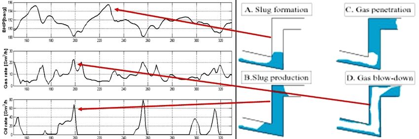
Study Group contributors

         Robert Bauer (University of Oxford)
     Steven Baxter (University of Nottingham)
       Christopher Bell (University of Oxford)
        Richard Booth (University of Oxford)
    John Byatt-Smith (University of Edinburgh)
       Rebecca Carter (University of Oxford)
       Paul Dellar (Imperial College London)
      John Fozard (University of Nottingham)
    Pragnesh Gajjar (University of Nottingham)
      John Garratt (University of Nottingham)
       Andriy Hold (University of Eindhoven)
       Sarah McBurnie (University of Oxford)
      Andrejs Novikovs (University of Oxford)
       John Ockendon (University of Oxford)
        Dharesh Patel (University of Baroda)
     Peter Stewart (University of Nottingham)
Burt Tilley (Franklin W. Olin College of Engineering)
Jean-Marc Vanden-Broeck (University of East Anglia)

               Report prepared by

          Melvin Brown (Smith Institute)
       Paul Dellar (Imperial College London)

                         2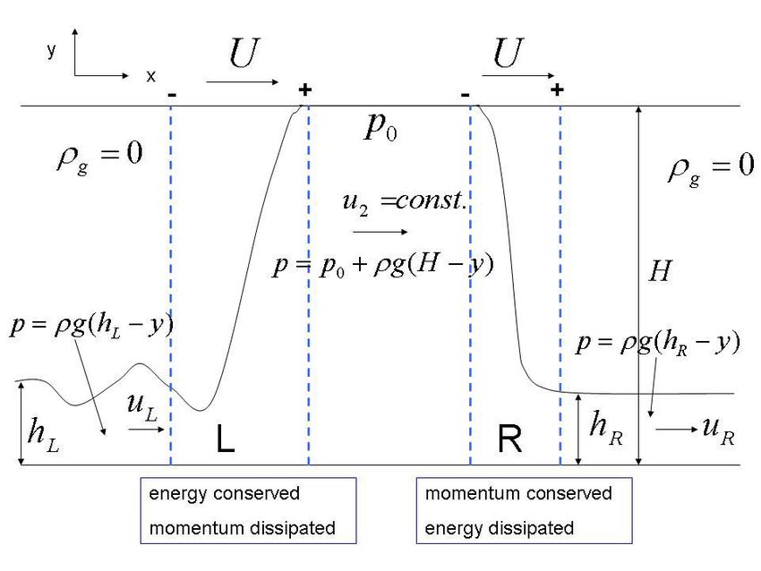
1     Introduction

1.1    Background and motivation

The growing world deficit between oil discovery and consumption makes optimising
production from existing fields increasingly important. When oil is produced, the
reservoir pressure decreases and the oil flow rate decreases in proportion to the decreasing
pressure difference between the reservoir and the processing facility. At low oil flow rates,
a well becomes unstable and this leads to reduced production and processing problems.
The formation of slug flow in pipelines, particularly at bends in the vertical plane is a
manifestation of such instability.
The description and classification multi-phase flows in a pipe or tube (figure 1), and the
use of flow-maps (figure 2) to estimate expected flow regimes under given circumstances
is well-established (Butterworth & Hewitt 1977).

                            Figure 1: Two-phase flow regimes

The incidence of different flow patterns depends on the relative flow rates of each
component. The characteristics of slug flow are intermittency and gas entrainment at
the front of the propagating slug. In this case multi-phase fluid slugs may travel at
velocities of up to 2 − 3 ms−1 along the inside of a pipe, each filling the full cross-section
over a finite length and each bounded before and after by stratified flows. There is a
strong dependence on initial conditions, and on pipe inclination, as shown in figure 3. In
this context, the total flow comprises a mixture of oil, water, gas and solid particles; it
is almost always fully turbulent with complex free boundaries and subject to multi-scale
effects. The presence of slug flow at a given point along a pipeline may be manifested
by apparently random variations, with respect to time, of pressure (188 − 196 bar), gas

                                             3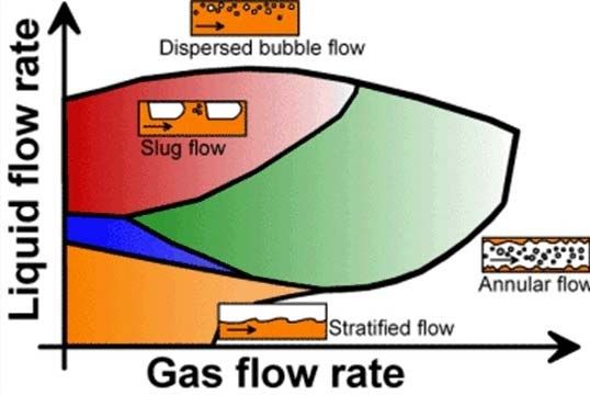
Figure 2: Two-phase flow map

volume flow rate (1 − 20 Sm3 hr−1 ), and oil volume flow rate (0 − 80 Sm3 hr−1 )1 , where
the exemplified numerical ranges are from figure 3. Large slugs are difficult to handle
and potentially damaging for processing units.

                    Figure 3: Transients for a bend in the vertical plane

The front of a slug may be regarded as a propagating, continuously breaking wave,
which continuously entrains gas. The amount of gas entrainment has a large impact
on flow pattern, pressure drop, and the slug length and propagation velocity, each of
which affect decisions about how to optimise production. Hence the interest of Hydro in
gaining better understanding of gas entrainment in the slug flow regime. In particular,
the Study Group was asked to

       • explore alternative or new ways to treat the entrainment problem;
       • improve understanding of physical processess governing entrainment;
       • suggest models for the various phenomena.
   1
     Sm3 is the unit of standard volume at 15◦ C and 1.013 bar (one standard atmosphere). In the case
of oil, it is the volume after dissolved and entrained gases have been removed.

                                                 4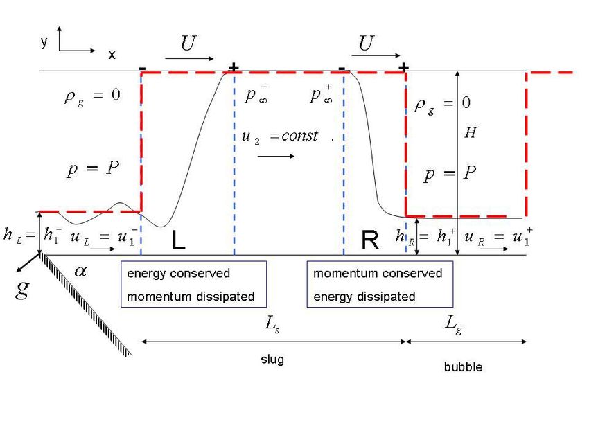
1.2     Current understanding and challenges

1.2.1   Theory and modelling

Understanding the physics of the gas-entrainment process at the slug front is difficult,
because of the complex turbulence phenomena, a large fraction of bubbles influencing the
turbulent properties, bubble-bubble interactions (coalescence and break-up), and other
effects. It is beyond current modelling capabilities to describe the slug flow process from
first principles. There are a number of simplified models of entrainment in slug flow, but
few capture any essential physics of the entrainment process. There is little consensus
regarding the physical effects that govern entrainment rate or what the precise influence
is of physical properties (densities, viscosities, surface tension, etc) on the entrainment
rate. There are six dimensionless groups which may be important in modelling gas
entrainment.

1.2.2   Experiments and data

Current understanding is based upon data from a number of experiments, but none
covers the full space of variables; moreoever, there is a lack of experimental data at high
pressures, where buoyancy forces are strongly reduced.
Experiments with density measurements provide a relation between the mean volume
fraction of gas in the slug as a function of the liquid and gas volume fluxes, Ql and Qg ,
but such ‘correlations’ are system specific and provide little data on the mechanisms of
entrainment.

Figure 4: Slug entrainment rate for a ‘push-in’ experiment, from Nydal & Andreussi
(1991).

In ‘push in’ experiments, a liquid plug is pushed into a pipe containing a liquid layer.
Such experiments indicate that the entrainment rate is proportional to pressure drop

                                            5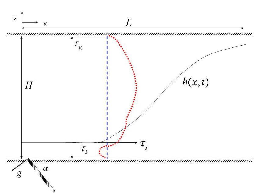
at the slug front (see figure 4, but it is likely that such result are dependent on
fluid properties and pipe dimensions. During the week, Study Group participants
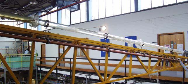
visited Barry Azzopardi’s slug flow experimental facility at Nottingham University. (See
figure 5.)
Figure 5: Barry Azzopardi’s slug flow experimental facility at Nottingham University.
A slug is travelling from right to left in the picture.
The unsteady nature of slug flow, means that it is a major challenge to obtain good and
accurate measured data for gas entrainment at the slug front. To overcome this problem,
experiments have been performed (Julshamn 2006) in which a steady hydraulic jump is
created in a pipe, enabling direct measurement of gas entrainment rates for different pipe
diameters and fluid properties (density, viscosity and surface tension). See, for example,
the arrangement in figure 6. Such experiments indicate that, in stationary hydraulic
jumps, entrainment is proportional to the Froude number of the upstream liquid film,
although there are no data on the influence of gas density. See figure 7.
1.3 Data provided to the Study Group
Hydro provided to the Study Group a copy of Julshamn’s PhD thesis (Julshamn 2006).
Julshamn’s thesis is about stationary hydraulic jumps, as depicted in figure 6. It contains
measurements of the air flow rate necessary to establish a stationary hydraulic jump for
a given liquid flow rate. See figure 7.
The thesis also has measurements of the pressure difference across the hydraulic jump,
and of the bubble size distributions downstream of the jump. It has many still pictures,
and formulates a model somewhat like that reported in section 4 below, though with
various extra approximations.
In Julshamn’s observation that more viscous flows entrain less (or at least look less
foamy), there is some support for the argument, at the end of section 4 of this report,
6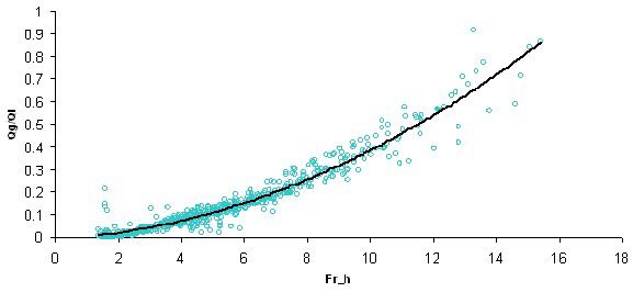
Figure 6: Experimental arrangement for a stationary hydraulic jump, from Julshamn
(2006).

for entrainment being proportional to turbulence levels. However, it is not clear whether
the velocities were the same for the different fluids.

2     Literature survey and approaches adopted
A literature survey revealed a vast number of publications on two-phase flow over many
decades and many in the area of slug flow, much of it addressing correlations for the slug
flow regime. Aside from Julshamn’s work (2006), there are models for hydraulic jumps
or bores, which have a single shock boundary (see for example Ockendon & Ockendon
(2004)). However, as basis for approaching the slug flow gas entrainment problem in the
Study Group, attention was given to modelling the propagation of slugs (which have two
shock boundaries).
Also found was work (particularly observational and experimental) on air entrainment in
hydraulic jumps and breaking waves, but less on the relationship between air entrainment
and energy loss, some of which is briefly reviewed below.

2.1    Energy dissipation and air entrainment

Experimental work on air entrainment in plunging breakers is exemplified by Chanson
et al. (2002) for which the entrainment is via the mechanism of the top of the wave
forming a water jet which runs ahead of the wave face and entraining air when it impacts
the free water surface ahead of the wave. This work provides evidence of the rise in free
surface level caused by entrainment for void fractions up to a maximum of ∼ 12% in the

                                           7
Figure 7: Entrainment rate as function of upstream Froude number for a stationary
hydraulic jump, from Julshamn (2006).
jet impact zone, and also suggests that bubble rise velocity is nearly constant for bubble
diameters ranging from 0.5 − 50 mm. The effect on the wave field of bulking (increase in
volume) caused by entrainment is also investigated.
An attempt at modelling the energy dissipation due to bubble entrainment is made by
Hoque & Aoki (2005), and it includes an analysis of a hydraulic jump. Using measured
void fraction data and a simple model based on the ongoing work done in raising the
centre of gravity of fluid at the jump front through bubble entrainment, Hoque & Aoki
suggest that ∼ 25% of the total hydraulic jump energy loss EH is dissipated in this way.
Here
(d2 − d1 )3
EH = ρl gV1 d1 , (1)
4d1 d2
where the depth d and velocity V at the inlet and outlet are indicated by subscripts
1 and 2 respectively, and d2 > d1 . Hoque & Aoki report that their fraction of ∼ 25%
energy dissipation through bubble entrainment is consistent with the values of 30 − 50%
reported in work by Lamarre & Melville (1991) on breaking waves. Very much smaller
(1 − 2%) bubble entrainment dissipation ratios were calculated by Hoque & Aoki (2005)
for vertical plunging jets.
3 Travelling slugs
The following models of travelling slug flow are expressed in terms of the variables and
parameters depicted in figure 8. U denotes the slug velocity and u a flow velocity. ρ
denotes density, and (when not a suffix) g the gravitational constant. The internal height
of the pipe is H, and h denotes the height of the liquid–gas boundary of the stratified
flow. P and p denote pressure. Subscripts L and R denote the left (trailing) and right
(leading) edges of a slug, and the subscripts l and g respectively denote a property of
the liquid and gas states.
8Figure 8: Horizontal pipe: variables and parameters for the travelling slug
3.1 Horizontal pipe
We assume a one dimensional shallow water model for a homogeneous fluid, and write
down equations for the conservation of mass, momentum, and energy:
∂t h + ∂x (hu) = 0, (2)
2 1 2
∂t (hu) + ∂x hu + gh = 0, (3)
2
1 2 1 2 1 3 1 2
∂t hu + gh + ∂x hu + gh u = 0. (4)
2 2 2 2
The integrated forms of these three conservation equations provide three jump conditions,
but there are only two variables h and u. We now assume that
• the leading shock front conserves mass and momentum, but dissipates energy;
• the trailing undular bore conserves mass and energy, but radiates momentum,
as depicted in figures 8 and 9.
Previous work (Fan et al. 1993) has considered a hydraulic jump at the front, and a
so–called Benjamin (1968) bubble at the back. Observations made of the experiment
9Figure 9: Horizontal pipe: scheme for mass, energy and momentum balances
depicted in figure 5, seemed to support the assumption that hL = hR = h, and that both
shocks move at the same speed u. Let δ = h/H.
The equations for conservation of mass at the left (L) and right (R) shock planes (as
depicted in figure 9) are
L : [h(u − U )]+
− = 0
R : [h(U − u)]+− = 0, (5)
which imply that
uL = u R = u1
u2 − U = δ(u1 − U ). (6)
The conservation of momentum at R gives
1
− − ρ0 H = 0,
[ρh(u − U )2 + ρgh2 ]+ (7)
2
while the conservation of energy at L gives
ρ ρg 2 +
[(U 2 + gh)(U − u)]+
−− [h u]− − P0 U2 H = 0. (8)
2g 2
10It was not at first apparent that this model has a serious deficiency. The assumptions
hL = hR and UL = UR , if taken at face value, assert that the shallow water expressions
for the energy and momentum downstream of the slug are equal to the expressions
for the energy and momentum upstream respectively. The model, however, assumes
that energy is dissipated at the leading hydraulic jump (at R), and that momentum is
dissipated at the trailing undular bore (at L). Solving the correct Rankine–Hugoniot
jump conditions then leads to the conclusion that the jump (at R) and the bore (at
L) are two infinitesimally weak (and thus reversible) shocks propagating with the fluid
speed. The slug speed U thus equals both UL and UR .
In hindsight, the energy required to entrain bubbles at the leading hydraulic jump is
found to be very small compared with the energy available in the oncoming flow. (See
Section 4.) Thus, one could easily gain the impression by eye, watching slugs in an
experimental set up like the one shown in figure 5, that the upstream and downstream
flow parameters (h and U ) are precisely equal, rather than just very close to each other.
In addition, the momentum lost from one member of a train of slugs through waves
radiating from a trailing undular bore would enter the leading hydraulic jump of the
next slug behind in the train.
3.2 Inclined pipe for F r 1
We now proceed with the analysis of the inclined pipe for large Froude number (F r 1),
without assuming that hL = hR = h. See figure 10.
The equations for conservation of mass at R and at L are
1 − U )h1 = (u2 − U )H
R : (u+ +
(9a)
L : (u− −
1 − U )h1 = (u2 − U )H. (9b)
The conservation of momentum at the leading edge R of the slug is
1 − U ) h1 = (u1 − U ) H − (P − p∞ )H,
(u+ 2 + 2 +
(10)
and the conservation of energy at the trailing edge L of the slug is
1 − 2 − 1
(u1 ) (u1 − U ) − (u2 )2 (u2 − U ) = (p−
∞ − P )u2 H. (11)
2 2
The pressure drop in the slug is
−
∞ − p∞ = −gLs sin (α),
p+ (12)
and the pressure drop in the film is
1 1 − 2
1 ) − (U − u1 ) = gLg sin (α).
(U − u+ 2
(13)
2 2
We prescribe the liquid flux
Ql = u+ +
1 h1 , (14)
11Figure 10: Inclined pipe: scheme for mass, energy and momentum balances
and the gas flux
Lg
Qg ≈ U H . (15)
Lg + Ls
Without loss of generality, we can take P = 0.
Thus, we have 8 equations and 10 unknowns, which therefore have a two parameter
family of solutions. What selection criteria can be used? Further work is required; for
example, taking the pressure drop in equations (12) and (13) to be purely hydrostatic
seems inconsistent with assuming large Froude number and hence weak gravity.
3.3 Inviscid 2D potential flow
Lee & Vanden-Broeck (1999) have carried out an analysis of the flow of two-dimensional
bubbles in an inclined tube of inviscid fluid. As the inclination angle α of the tube from
the horizontal increases, they find that the critical Froude number F r∗ (α), below which
a slug bubble may exist, increases from 0.4 to above 0.5 and then decreases to 0.3 in
the vertical position. (Here, we are concerned with 0 ≤ α ≤ π/2.) This result is in
good agreement with Bendikson’s (1984) experimental measurements of F r∗ (α). Lee &
Vanden-Broeck (1999) also gave the velocity of a bubble in moving fluid as
U = CB Uliquid + U0 , (16)
12but with CB = 1 instead of Bendikson’s value CB = 1.2. Here U0 is the speed of a bubble
in quiescent liquid, and Uliquid is the speed of any additional motion of the liquid relative
to the tube walls.
However, Lee & Vanden-Broeck’s (1999) theory is for inviscid fluids, and therefore
invariant under Galilean transformations along the axis of the tube. This explains why
CB = 1 precisely in their theory. A bubble in a real fluid will experience viscous drag
when moving relative to the tube walls. The tube therefore defines a preferred frame,
which is why the experimental value of CB differs from the inviscid value.
4 Entrainment - energy dissipation rate
We now provide an approximate analysis of the gas entrainment in the leading edge
of the slug in the horizontal pipe configuration. The domain of analysis is depicted in
figure 11. We assume a homogeneous mixture of gas and liquid with a void fraction φ,
and a single velocity Um . We thus neglect any relative motion between the bubbles and
the liquid.
Figure 11: Scheme for modelling gas entrainment rate
The experimentally-measured pressure jump is of the order of 1 kPa, the same order
of magnitude as the hydrostatic pressure difference across a few centimetres of water.
13These two pressures are both much smaller than atmospheric pressure, 1 atm ∼ 105 Pa,
so we ignore any compression of the gas phase due to changes in pressure.
Conservation of mass (now equivalent to conservation of volume) for the liquid and gas
phases then gives
HUm φ = (H − h)Ug (17a)
HUm (1 − φ) = hUl (17b)
for a steady hydraulic jump. Solving for the void fraction φ, we obtain
1
φ= . (18)
hUl
1+
(H − h)Ug
The momentum conservation determines the pressure jump, and the energy
equation determines the dissipation rate. We are thus left without any relation between
the three upstream quantities h, Ul , Ug of the kind that might explain figure 7.
How much energy is required to create bubbles? The void fraction φ may be rewritten
as
4
φ = πr3 n, (19)
3
in terms of a typical bubble radius r, and the number of bubbles n per unit volume. The
surface energy per unit volume is then
Es = 4πr2 γ n = 3φ γ/r, (20)
where γ is the surface tension of an air/liquid interface.
The engineering literature (e.g. Barnea et al. 1982, Brauner & Ullmann 2004) assumes
that the bubble radius r should be estimated by the critical radius rc for which surface
tension, tending to create spherical bubbles, just balances the distorting effects of
buoyancy,
1/2
0.4γ
rc = ∼ 1 mm, (21)
(ρl − ρg )g
when evaluated using γ ∼ 3 × 10⁻² Nm−1 for a kerosene and air mixture.
The surface energy per unit volume is then
Es ∼ 100φ Nm−2 ∼ 0.1φ kPa, (22)
which is much smaller than the pressure drop across the hydraulic jump (typically
1 kPa as above). At first sight, it therefore seems unlikely that the surface energy
of bubbles is responsible for setting the void fraction downstream of the hydraulic jump.
A hypothesis relating surface energy to energy dissipation was considered early in the
week, but discarded on the basis of these order-of-magnitude estimates.
14However, a similar hypothesis is used in the engineering literature (Chen et al. 1997,
Zhang et al. 2003), but with the modification that only the turbulent part of the kinetic
energy of the upstream flow is available for creating bubbles. The Reynolds number
based on the upstream flow is large, so the flow will typically be turbulent. There will
thus be many small-scale turbulent fluctuations superimposed upon the mean flow, the
flow indicated by the velocity Ul in figure 11. The fluctuations are usually defined as
deviations from some spatially-averaged flow field.
The magnitude of the fluctuations is typically estimated using the friction velocity u ,
u = (τ /ρL )1/2 , (23)
where τ is the shear stress at the wall, and ρL the density of the liquid phase. The mean
streamwise velocity Ul is related to the friction velocity u via the log-law velocity profile
equation
Ul 1 Hu u
= log Re + 5.5, where Re = = Re . (24)
u k ν Ul
Re is the Reynolds number based on the friction velocity u , k = 0.4 is von Karman’s
constant, and 5.5 is another empirical constant. Equation (24) is often rewritten in terms
of the Fanning friction factor fF = 2u 2 /Ul2 ,
−1/2 1/2
fF = 4 log10 (Re fF ) − 0.4, (25)
as in equation (19) of Goldstein (1938), §154, though using γ instead of fF . Thus
1
f = u 2 /Ul2 is the fraction of the kinetic energy associated with turbulent eddies.
2 F
For Re 105 , Blasius proposed an approximate explicit formula for fF , equation 20 in
Goldstein (1938) §155,
fF = 0.0665(Ul H/ν)−1/4 = 0.0665Re−1/4 . (26)
Julshamn’s experiments were characterised by friction factors in the range 0.015 ≤ fF ≤
0.035, corresponding to Reynolds numbers in the range 7000 ≤ Re ≤ 160 000. Balancing
the surface energy given by (22) with the friction factor that multiplies the pressure drop
(typically 1 kPa) across the hydraulic jump, we get
0.1φ ∼ fF , so 0.15 ≤ φ ≤ 0.35,
which is not unreasonable.
Andritsos & Hanratty (1987) have suggested that waves on the gas/liquid interface may
lead to a larger effective friction factor, which leads into the following section on long
wave models for the onset of a hydraulic jump.
5 Long wave model
This approach is based on the idea of a simple dynamical model to determine the pressure
conditions for the onset of slug flow. The configuration for the analysis is depicted in
figure 12.
15Figure 12: Scheme for the long wave model
Assume the pressure is solved by
1
∂
udz = 0, (27)
∂x 0
with u taking different values in the liquid phase (z < h) and the gas phase (z > h).
Conservation of the masses of liquid and gas then gives the following relations
h
∂
ht + udz = −J (28a)
∂x 0
φx h
φ+ udz = −J, (28b)
h 0
where J is the mass flux of gas into the liquid. If we assume that J = −μe hxx , then
entrainment would act to stabilize the interface, which suggests that a better model for
J should be investigated.
The main point would be to find an entrainment model J which is based on the local
vorticity of the flow, and which depends on void fraction. Any velocity difference
between the liquid and gas velocities tends to cause Kelvin–Helmholtz instabilities at
the liquid/gas interface. Conversely, the larger density of the liquid will tend to stabilise
disturbances of the interface, but entrainment of gas will reduce the density of the lower,
16predominantly liquid, phase. The rolling up of Kelvin–Helmholtz billows formed through
these two competing mechanisms is a natural model for entrainment. A model for J can
then be put into equations (28) to close the model.
Could entrainment be the mechanism that, when included, resolved the following issues?
That is, to the left of L in figure 10, entrainment provides the momentum ‘dissipation’,
while at R bubbles under the slug moving into the gas ‘dissipate’ energy? Is it possible
to put in a fixed mass flux J and see if the momentum/energy jumps that are consistent
with this mass flux are also consistent with dissipation for each of these layers?
6 Conclusions
The work reported must be regarded as in progress. Although the objective is to better
understand gas entrainment in slug flow, much of the effort during the Study Group
was expended on developing models of the phenomenon of slug flow and its onset, as a
foundation for studying the gas entrainment processes. The following areas are suggested
for further work.
• A feature of the derived model of slug flow for large Froude number is that the
number of equations is two less than the number of unknowns. Thus, for example
the length of the slug is undetermined. The model is based on momentum loss at
one end of the slug and energy loss at the other, and an assumed purely hydrostatic
pressure drop across the slug in the inclined pipe case. Further study of this model
is required.
• During the Study Group the notion of undular bores emitting waves from one slug
that feed momentum into the next slug along was discussed. Subsequently, there
has emerged the idea of developing a long wave model (something like shallow
water with a lid) that would support waves propagating from slug to slug, to study
the dynamics of trains of slugs.
• The work on gas entrainment focused on the hydraulic jump and found the surface
energy per unit volume of bubbles to between 1 and 2 orders of magnitude lower
than the pressure drop across the jump. This is substantially less than the 25%
suggested in Hoque & Aoki (2005) for entrainment energy loss in hydraulic jumps,
but closer to the 1 − 2% reported by them for vertical plunging jets. Having
originally rejected a link between kinetic energy dissipation and formation of
bubble surface energies, based on order-of-magnitude estimates, the Study Group
later began investigating the suggestion in the literature that only the turbulent
part of the upstream flow is available for the creation of bubbles. In pursuit of
this suggestion, preliminary work on friction factors reported here finds that the
turbulent energy is consistent with bubble surface energies for void fractions in the
range 0.15 ≤ φ ≤ 0.35. Further work is required to properly study this encouraging
finding.
17• The Study Group gave attention primarily to the large Froude number
approximation, as in Julshamn’s thesis (Julshamn 2006), which neglects
hydrostatic pressures. The finite Froude number analysis is believed to be tractable
and is worthy of further work.
• Work was also started on a long wave model to gain insight into the conditions for
the onset of slug flow and a mechanism whereby entrainment acts to stabilise
leading the surface of the slug or jump. Further work is required to develop
and investigate a void fraction dependent entrainment model based on local flow
vorticity.
References
Andritsos, N. & Hanratty, J. T. (1987) Influence of interfacial waves in stratified
gas-liquid flows. AICHE J. 33, 444–454.
Barnea, D., Shoham, O. & Taitel, Y. (1982) Flow pattern transition for vertical
downward two phase flow. Chem. Eng. Sci. 37, 741–744.
Bendiksen, K. H. (1984) An experimental investigation of the motion of long bubbles
in inclined tubes. Int. J. Multiphase Flow 10, 467–483.
Benjamin, T. (1968) Gravity currents and related phenomena. J. Fluid Mech. 31,
209–248.
Brauner, N. & Ullmann, A. (2004) Modelling of gas entrainment from Taylor
bubbles. Part B: A stationary bubble. Int. J. Multiphase Flow 30, 273–290.
Butterworth, D. & Hewitt, G. F. (1977) Two-Phase Flow and Heat Transfer .
Oxford: Oxford University Press.
Chanson, H., Aoki, S.-I. & Maruyama, M. (2002) Unsteady air bubble entrainment
and detrainment at a plunging breaker: dominant time scales and similarity of water
level variations. Coastal Eng. 46, 139–157.
Chen, X. T., Cai, X. D. & Brill, J. P. (1997) A general model for transition to
dispersed bubble flow. Chem. Eng. Sci. 52, 4373–4380.
Fan, Z., Ruder, Z. & Hanratty, T. J. (1993) Pressure profiles for slugs in horizontal
pipelines. Int. J. Multiphase Flow 19, 421–437.
Goldstein, S., ed. (1938) Modern Developments in Fluid Dynamics. Oxford: Oxford
University Press.
Hoque, A. & Aoki, S.-I. (2005) A quantitative analysis of energy dissipation among
three typical air entrainment phenomena. Environ. Fluid Mech. 5, 325–340.
Julshamn, J. A. (2006) Hydraulic jumps in horizontal two-phase pipe flow. PhD thesis,
Norwegian University of Science and Technology (NTNU), Trondheim.
18Lamarre, E. & Melville, W. K. (1991) Air entrainment and dissipation in breaking
waves. Nature 351, 469–472.
Lee, J. & Vanden-Broeck, J.-M. (1999) Bubbles rising in an inclined two-
dimensional tube and jets falling along a wall. J. Austral. Math. Soc. Ser. B 39,
332–349.
Nydal, O. J. & Andreussi, P. (1991) Gas entrainment in a long liquid slug advancing
in a near horizontal pipe. Int. J. Multiphase Flow 17, 179–189.
Ockendon, H. & Ockendon, J. R. (2004) Waves and Compressible Flow . Springer.
Zhang, H.-Q., Wang, Q., Sarica, C. & Brill, J. P. (2003) A unified mechanistic
model for slug liquid holdup and transition between slug and dispersed bubble flows.
Int. J. Multiphase Flow 29, 97–107.
19You can also read