GM - Miniatur Magnet GM - Miniature solenoid
←
→
Page content transcription
If your browser does not render page correctly, please read the page content below
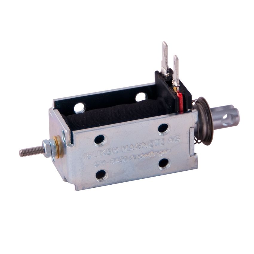
ISLIKER MAGNETE

 GM - Miniatur Magnet

 GM - Miniature solenoid

ISLIKER MAGNETE AG - CH-8450 Andelfingen - Tel. +41 (0)52 305 25 25 - info@islikermagnete.ch - www.islikermagnete.ch
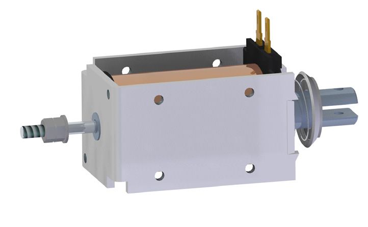
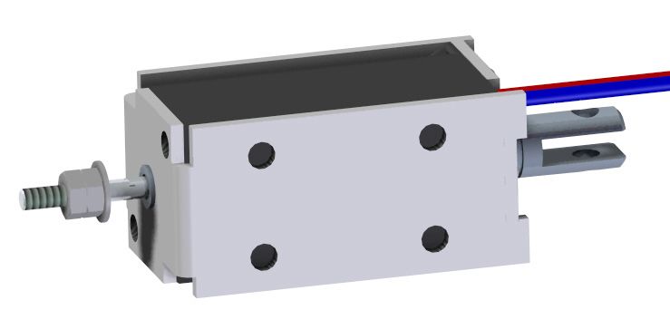
GM		            Miniatur-Magnet Übersicht
GM		            Miniature solenoid overview
                                                                                  ISLIKER MAGNETE

                  Baureihe            Dimensionen           Hub                 Fmin
                  GM-20.05            23 x 20 x 40          5                   2
                  GM-26.08            30 x 26 x 50          8                   5.5
                  GM-35.10            40 x 35 x 60          10                  9

                  Type                Dimensions            Stroke              Fmin
                  GM-20.05            23 x 20 x 40          5                   2
                  GM-26.08            30 x 26 x 50          8                   5.5
                  GM-35.10            40 x 35 x 60          10                  9

ISLIKER MAGNETE AG - CH-8450 Andelfingen - Tel. +41 (0)52 305 25 25 - info@islikermagnete.ch - www.islikermagnete.ch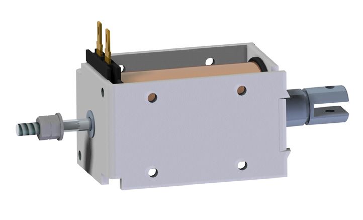
GM-20.05 Miniatur-Magnet
GM-20.05 Miniature solenoid
ISLIKER MAGNETE
20
6.8
10 1.7
Ausführung I Ausführung II
Execution I Execution II
11.5
4
M4
10 M
5
3.2
O7
20
12
14
Stossseite Zugseite
23 Push side 10 20 Pull side 14
Magnet bestromt gezeichnet
Solenoid illustrated in energised position
Hub / stroke = 5
5
2
Max. Einschraubtiefe der 3.
M2.5
Befestigungsschrauben O
ist 2 mm
O 15
O7
Max. depth of thread
for fixing screw = 2 mm
10
0.5 10 Mit Federrückstellung
15 41 14 with return spring
15
ED % 100 40 25 15 5 Duty cycle %
10 Die Spieldauer für The max. duty cycle
5% die Berechnung der time to determine the
8 Einschaltdauer beträgt duty cycle is 30 sec.
30 sec.
6
Kraft (Fn) / Force Fn [N]
15% Hubarbeit Ncm 1.0 1.8 2.2 2.6 5.2 Work done Ncm
4
25% El. Leistung W 9 19 27 47 170 Power Watts
(P20) (P20)
40%
2 Anzugszeit ms 45 44 42 41 40 Operating time ms
F2.0 Abfallzeit ms 30 27 24 21 18 Release time ms
F1.3 (@20°C, betriebs- (@20°C, operating
100% warm, bei Belastung temperature, with a
1 mit 70% der entspre- load equal to 70% of
chenden Magnetkraft) the solenoid force)
0.8
Federcharakteristik
0.6 F0.6 Spring characteristic = Nicht Standard / not standard
0.5
0 2 4 5 6 8 10
2012-11 1.1
Hub / stroke [mm]
ISLIKER MAGNETE AG - CH-8450 Andelfingen - Tel. +41 (0)52 305 25 25 - info@islikermagnete.ch - www.islikermagnete.ch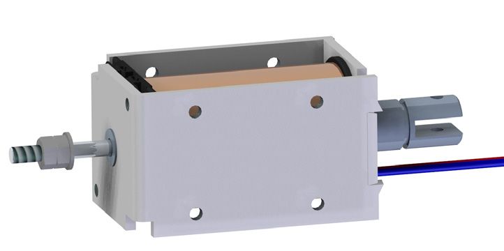
GM-20.05                  Miniatur-Magnet
GM-20.05                  Miniature solenoid
                                                                                                            ISLIKER MAGNETE

Spezifikationen                                                                                                      Specifications

     Funktion                               Ziehend / stossend                         Pull / Push                   Operation
     Vorzugs-Nennspannung                                    24 VDC (max. 50 VDC)                                    Preferred rated voltage
     Isolierstoffklasse                                     F (155°C) DIN VDE 0580                                   Class of insulation
     Prüfspannung                                                  EN 60664-1                                        Test voltage
     Überspannungskategorie                                            III                                           Surge category
     Schutzart                                                   IP00 (IEC 60529)                                    Degree of protection
     El. Anschlussart                Steckzungen 2.8 x 0.8 DIN 46342-1          2.8 x 0.8 Tabs DIN 46342-1           Electrical termination
                                        Litzen (300 mm), AWG22                Lead wires (300 mm), AWG22
     Oberflächenbehandlung          Gehäuse verzinkt & blau passiviert,    Solenoid housing zinc plated & tri-       Surface treatment
                                          Anker hartverchromt              valent chrome passivated, Plunger
                                                                                   hard chrome-plated
     bewegte Masse                                                   0.013 kg                                        Moving mass
     Total Magnetgewicht                                             0.075 kg                                        Total weight of solenoid

Bestellbeispiel                                                                                      Ordering specification

                                      GMs - 20.05 - 100 U - 24 I F 0.6
Gleichstrom-Miniatur-Magnet                                                                          Type GM: D.C. Miniature Solenoid
s: mit Stossstange                                                                                   s:     with push rod
ohne Index keine Stossstange                                                                                without push rod - no index
Baugrösse                                                                                            Size
Nennhub des Magneten in mm                                                                           Rated stroke of solenoid in mm
Einschaltdauer (ED) in %                                                                             Duty cycle in %
U: Universalanschluss                                                                                U: Universal termination
W: Litzenanschluss                                                                                   W: Lead wire
Spannung in Volt                                                                                     Voltage
I       Anschlüsse auf Stossseite                                                                    I      Electrical termination on push side
II      Anschlüsse auf Zugseite                                                                      II     Electrical termination on pull side
Mit Rückstellfeder                                                                                   With return-spring assembly
Ohne Rückstellfeder kein Index                                                                       Without spring - no index
Index der Federkennlinie                                                                             Index of return-spring

Bemerkungen                                                               Notes
1) Magnetkraft betriebswarm gemessen bei 20°C                             1) Forces indicated measured at 20°C ambient and operating
   Umgebungstemperatur, waagrechter Bewegungsrichtung                        temperature with 90% of its rated voltage, in horizontal position
   mit 90% Nennspannung

2) Die Magnetkraftwerte gelten nur als Referenzwerte                      2) Force values for reference only

3) Sonderausführungen sind lieferbar                                      3) Special solenoids are available

4) Änderungen vorbehalten - Abbildungen unverbindlich                     4) All specifications subject to change without notice

5) Magnete hergestellt und geprüft nach DIN VDE 0580                      5) Solenoid manufactured and tested according to DIN VDE 0580

6) RoHS konform                                                           6) Compliant with RoHS

7) Weitere Hinweise in den „Technischen Erläuterungen“ und                7) More details see „Technical Explanations“
   der „Herstellererklärung der ISLIKER MAGNETE“                             and „Manufacturer‘s declaration“
                                                                                                                                                  2012-11 1.1

ISLIKER MAGNETE AG - CH-8450 Andelfingen - Tel. +41 (0)52 305 25 25 - info@islikermagnete.ch - www.islikermagnete.ch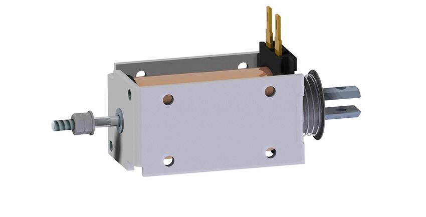
GM-26.08 Miniatur-Magnet
GM-26.08 Miniature solenoid
ISLIKER MAGNETE
26 6.2
Ausführung I Ausführung II
10 Execution I 1.2 Execution II
11.5
4
M4
M
12
4
4.2
O9
26
18
20
Stossseite Zugseite
30 Push side 10 30 Pull side 20
Magnet bestromt gezeichnet
Solenoid illustrated in energised position
Hub / stroke = 8
8
.2
O3
Max. Einschraubtiefe der
Befestigungsschrauben
ist 3 mm
O 20
O7
M3
Max. depth of thread
for fixing screw = 3 mm 12
0.5 15 Mit Federrückstellung
20 50 20 with return spring
20
ED % 100 40 25 15 5 Duty cycle %
18 5%
Die Spieldauer für The max. duty cycle
die Berechnung der time to determine the
16 Einschaltdauer beträgt duty cycle is 30 sec.
Kraft (Fn) / Force (Fn) [N]
30 sec.
14
Hubarbeit Ncm 4.2 6.0 7.4 9.0 14.2 Work done Ncm
12
15%
El. Leistung W 12 28 40 60 200 Power Watts
(P20) (P20)
10
25%
8 Anzugszeit ms 65 62 60 57 55 Operating time ms
40% Abfallzeit ms 45 40 35 30 25 Release time ms
6 (@20°C, betriebs- (@20°C, operating
F5.0 100% warm, bei Belastung temperature, with a
4 mit 70% der entspre- load equal to 70% of
F3.0 chenden Magnetkraft) the solenoid force)
Federcharakteristik
2
F0.8 Spring characteristic = Nicht Standard / not standard
0
0 2 4 6 8 10 12
2012-11 1.1
Hub / stroke [mm]
ISLIKER MAGNETE AG - CH-8450 Andelfingen - Tel. +41 (0)52 305 25 25 - info@islikermagnete.ch - www.islikermagnete.ch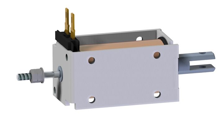
GM-26.08                  Miniatur-Magnet
GM-26.08                  Miniature solenoid
                                                                                                            ISLIKER MAGNETE

Spezifikationen                                                                                                      Specifications

     Funktion                               Ziehend / stossend                         Pull / Push                   Operation
     Vorzugs-Nennspannung                                    24 VDC (max. 50 VDC)                                    Preferred rated voltage
     Isolierstoffklasse                                     F (155°C) DIN VDE 0580                                   Class of insulation
     Prüfspannung                                                  EN 60664-1                                        Test voltage
     Überspannungskategorie                                            III                                           Surge category
     Schutzart                                                   IP00 (IEC 60529)                                    Degree of protection
     El. Anschlussart                Steckzungen 2.8 x 0.8 DIN 46342-1          2.8 x 0.8 Tabs DIN 46342-1           Electrical termination
                                        Litzen (300 mm), AWG20                Lead wires (300 mm), AWG20
     Oberflächenbehandlung          Gehäuse verzinkt & blau passiviert,    Solenoid housing zinc plated & tri-       Surface treatment
                                          Anker hartverchromt              valent chrome passivated, Plunger
                                                                                   hard chrome-plated
     bewegte Masse                                                   0.027 kg                                        Moving mass
     Total Magnetgewicht                                             0.180 kg                                        Total weight of solenoid

Bestellbeispiel                                                                                      Ordering specification

                                      GMs - 26.08 - 100 U - 24 I F 0.8
Gleichstrom-Miniatur-Magnet                                                                          Type GM: D.C. Miniature Solenoid
s: mit Stossstange                                                                                   s:     with push rod
ohne Index keine Stossstange                                                                                without push rod - no index
Baugrösse                                                                                            Size
Nennhub des Magneten in mm                                                                           Rated stroke of solenoid in mm
Einschaltdauer (ED) in %                                                                             Duty cycle in %
U: Universalanschluss                                                                                U: Universal termination
W: Litzenanschluss                                                                                   W: Lead wire
Spannung in Volt                                                                                     Voltage
I       Anschlüsse auf Stossseite                                                                    I      Electrical termination on push side
II      Anschlüsse auf Zugseite                                                                      II     Electrical termination on pull side
Mit Rückstellfeder                                                                                   With return-spring assembly
Ohne Rückstellfeder kein Index                                                                       Without spring - no index
Index der Federkennlinie                                                                             Index of return-spring

Bemerkungen                                                               Notes
1) Magnetkraft betriebswarm gemessen bei 20°C                             1) Forces indicated measured at 20°C ambient and operating
   Umgebungstemperatur, waagrechter Bewegungsrichtung                        temperature with 90% of its rated voltage, in horizontal position
   mit 90% Nennspannung

2) Die Magnetkraftwerte gelten nur als Referenzwerte                      2) Force values for reference only

3) Sonderausführungen sind lieferbar                                      3) Special solenoids are available

4) Änderungen vorbehalten - Abbildungen unverbindlich                     4) All specifications subject to change without notice

5) Magnete hergestellt und geprüft nach DIN VDE 0580                      5) Solenoid manufactured and tested according to DIN VDE 0580

6) RoHS konform                                                           6) Compliant with RoHS

7) Weitere Hinweise in den „Technischen Erläuterungen“ und                7) More details see „Technical Explanations“
   der „Herstellererklärung der ISLIKER MAGNETE“                             and „Manufacturer‘s declaration“
                                                                                                                                                  2012-11 1.1

ISLIKER MAGNETE AG - CH-8450 Andelfingen - Tel. +41 (0)52 305 25 25 - info@islikermagnete.ch - www.islikermagnete.ch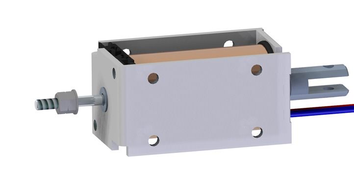
GM-35.10 Miniatur-Magnet
GM-35.10 Miniature solenoid
ISLIKER MAGNETE
26 6.7
Ausführung I Ausführung II
10 Execution I 1.7 Execution II
4 11
4
4
M
M
12
4.2
O 12
35
25
28
Stossseite Zugseite
40 Push side 15 30 Pull side 28
Magnet bestromt gezeichnet
Solenoid illustrated in energised position
12
Hub / stroke = 10
3.2
Max. Einschraubtiefe der
O
Befestigungsschrauben
O 24.5
ist 4 mm
O9
M4
Max. depth of thread
for fixing screw = 4 mm
15
0.5 20 Mit Federrückstellung
25 60 25 with return spring
40
ED % 100 40 25 15 5 Duty cycle %
35 Die Spieldauer für The max. duty cycle
die Berechnung der time to determine the
5% Einschaltdauer beträgt duty cycle is 30 sec.
Kraft (Fn) / Force (Fn) [N]
30 30 sec.
Hubarbeit Ncm 11 16 18 22 32 Work done Ncm
25
15% El. Leistung W 20 50 80 134 400 Power Watts
(P20) (P20)
20
25%
40% Anzugszeit ms 110 100 85 80 75 Operating time ms
15 Abfallzeit ms 80 65 60 55 50 Release time ms
F11 (@20°C, betriebs- (@20°C, operating
100%
10 warm, bei Belastung temperature, with a
mit 70% der entspre- load equal to 70% of
F6.0 chenden Magnetkraft) the solenoid force)
5
Federcharakteristik
F1.5 Spring characteristic = Nicht Standard / not standard
0
0 2 4 6 8 10 12 14
2012-11 1.1
Hub / stroke [mm]
ISLIKER MAGNETE AG - CH-8450 Andelfingen - Tel. +41 (0)52 305 25 25 - info@islikermagnete.ch - www.islikermagnete.ch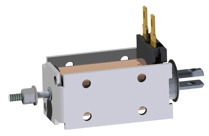
GM-35.10                  Miniatur-Magnet
GM-35.10                  Miniature solenoid
                                                                                                            ISLIKER MAGNETE

Spezifikationen                                                                                                      Specifications

     Funktion                               Ziehend / stossend                         Pull / Push                   Operation
     Vorzugs-Nennspannung                                    24 VDC (max. 50 VDC)                                    Preferred rated voltage
     Isolierstoffklasse                                     F (155°C) DIN VDE 0580                                   Class of insulation
     Prüfspannung                                                  EN 60664-1                                        Test voltage
     Überspannungskategorie                                            III                                           Surge category
     Schutzart                                                   IP00 (IEC 60529)                                    Degree of protection
     El. Anschlussart                Steckzungen 2.8 x 0.8 DIN 46342-1          2.8 x 0.8 Tabs DIN 46342-1           Electrical termination
                                        Litzen (300 mm), AWG20                Lead wires (300 mm), AWG20
     Oberflächenbehandlung          Gehäuse verzinkt & blau passiviert,    Solenoid housing zinc plated & tri-       Surface treatment
                                          Anker hartverchromt              valent chrome passivated, Plunger
                                                                                   hard chrome-plated
     bewegte Masse                                                   0.058 kg                                        Moving mass
     Total Magnetgewicht                                             0.420 kg                                        Total weight of solenoid

Bestellbeispiel                                                                                      Ordering specification

                                      GMs - 35.10 - 100 U - 24 I F 1.5
Gleichstrom-Miniatur-Magnet                                                                          Type GM: D.C. Miniature Solenoid
s: mit Stossstange                                                                                   s:     with push rod
ohne Index keine Stossstange                                                                                without push rod - no index
Baugrösse                                                                                            Size
Nennhub des Magneten in mm                                                                           Rated stroke of solenoid in mm
Einschaltdauer (ED) in %                                                                             Duty cycle in %
U: Universalanschluss                                                                                U: Universal termination
W: Litzenanschluss                                                                                   W: Lead wire
Spannung in Volt                                                                                     Voltage
I       Anschlüsse auf Stossseite                                                                    I      Electrical termination on push side
II      Anschlüsse auf Zugseite                                                                      II     Electrical termination on pull side
Mit Rückstellfeder                                                                                   With return-spring assembly
Ohne Rückstellfeder kein Index                                                                       Without spring - no index
Index der Federkennlinie                                                                             Index of return-spring

Bemerkungen                                                               Notes
1) Magnetkraft betriebswarm gemessen bei 20°C                             1) Forces indicated measured at 20°C ambient and operating
   Umgebungstemperatur, waagrechter Bewegungsrichtung                        temperature with 90% of its rated voltage, in horizontal position
   mit 90% Nennspannung

2) Die Magnetkraftwerte gelten nur als Referenzwerte                      2) Force values for reference only

3) Sonderausführungen sind lieferbar                                      3) Special solenoids are available

4) Änderungen vorbehalten - Abbildungen unverbindlich                     4) All specifications subject to change without notice

5) Magnete hergestellt und geprüft nach DIN VDE 0580                      5) Solenoid manufactured and tested according to DIN VDE 0580

6) RoHS konform                                                           6) Compliant with RoHS

7) Weitere Hinweise in den „Technischen Erläuterungen“ und                7) More details see „Technical Explanations“
   der „Herstellererklärung der ISLIKER MAGNETE“                             and „Manufacturer‘s declaration“
                                                                                                                                                  2012-11 1.1

ISLIKER MAGNETE AG - CH-8450 Andelfingen - Tel. +41 (0)52 305 25 25 - info@islikermagnete.ch - www.islikermagnete.ch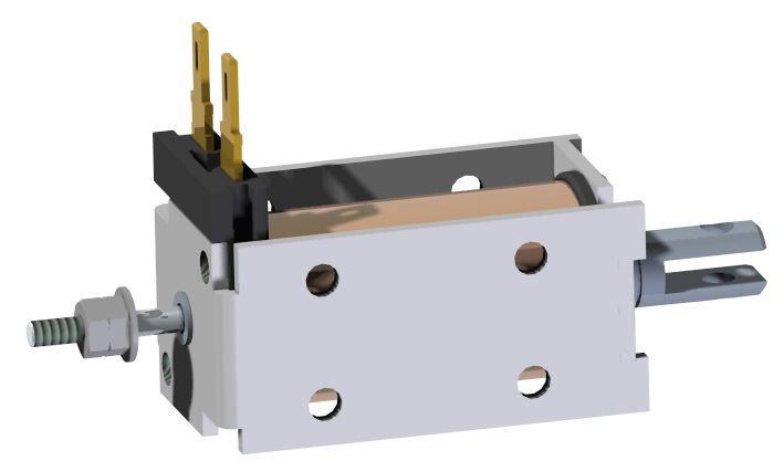
You can also read