Guidelines Dimensions of lighting fixtures in .IES and .LDT files - Viso Systems
←
→
Page content transcription
If your browser does not render page correctly, please read the page content below
Guidelines
Dimensions of lighting fixtures in .IES and .LDT files
                                            Revision: January 2021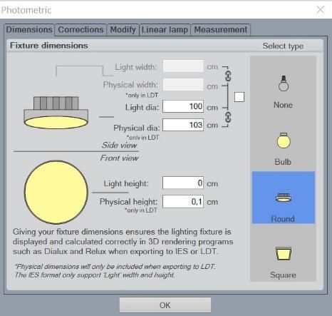
Contents
    About export to .IES and .LDT formats..........................................................................3
    Aligning the fixture .......................................................................................................3
    Typing dimensions into the system ..............................................................................4
    UGR tables ....................................................................................................................4
    Working with Viso outputs in LDT Editor ......................................................................5
    EULUMDAT - .LDT file format specification ..................................................................6
    .IES file format specification .........................................................................................8

    For news, Q&A and support at Viso Systems, visit our website at
    www.visosystems.com

    Other guidelines and manuals for Viso products can be downloaded from
    www.visosystem.com

2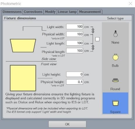
About export to .IES and .LDT formats
Viso Systems’ software – Light Inspector – can export light measurement data in
both .IES and .LDT formats. Both export file formats are intended for posterior
processing in lighting design software such as Relux and Dialux.
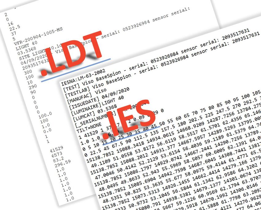
The .IES1 format is primarily used in the US, while .LDT2 formats are used in Europe.
Both are text formats and contain much of the same information:
• Some general information about the measurement
• Lighting fixture data – also diameter or length, width and height
• Light distribution in all planes and full resolution – a matrix of c and γ
values
Aligning the fixture
As the software does not “know” how the lighting fixture is actually positioned on
the goniometer, it is very important that the fixture is aligned in a way that the
“length” will actually be interpreted as “length” in posterior outputs. In other words,
make sure that the measurement starts with the fixture having the length being
parallel to c0-c180 on the goniometer.
γ angle 180°
Vertical
C270° C180°
Horizontal angles Horizontal angles
= c-planes = c-planes
Height
C0° C90°
γ angle 0°
Vertical
Direction toward
Viso Sensor
The image to the left shows the C-plane orientations of the LabSpion. BaseSpion and
LightSpion work the same way).
1
Standardized in ANSI/IESNA LM-63-02
2
Also called EULUMDAT. Not standardised, but proposed by Axel Stockmar
(Light Consult Inc., Berlin) in 1990
3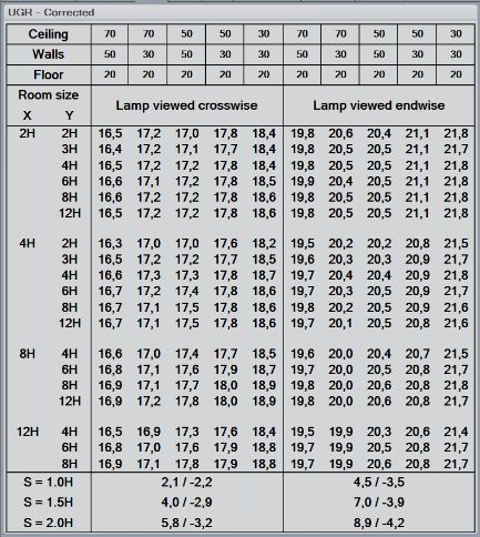
Typing dimensions into the system
    The fixture dimensions are easily entered in the Light Inspector software

    To calculate the correct light outputs for further visualization, it is necessary to insert
    the dimensions of the measured lighting fixtures (bulbs, spots and panels) in the
    table as shown in the figures. The table is found in:

    Edit → Photometric → Dimensions.

    Thus, this feature enables the data files to reflect the luminous and physical
    dimensions for an accurate visualization in 3D lighting software.

    UGR tables
    The Light Inspector calculates UGR (Unified Glare Rating) tables according to CIE 117-
    1995 and CIE 190:2010.

    The table allows you to evaluate the glare properties of a given light source through
    tabularized glare calculations based on standard spaces, reflectivity, viewing
    direction. Hence, the glare limits set forth in e.g., standard EN 12464-1 Light And
    Lighting – Lighting of Work Places – Part 1: Indoor Work Places and standard ISO
    8995-1:2002(E)/CIE S 008/E:2001 “Lighting of Workplaces – Part 1: Indoor can be
    evaluated during lighting design and planning.

    Again, getting the dimensions right is very important as the UGR table values are
    categorized “lengthwise” (meaning seen from the end of elongated fixture) and
    “crosswise” (meaning seen from the side).

    You need to enter two types of information:

         ▪    The dimensions of the luminous area are manually entered as described in
              Edit → Photometric → Dimensions.
         ▪    You need to correct symmetry to either circular symmetry or V and H
              symmetry (Click Edit → Photometric → Corrections. Check box “Correct
              asymmetry”, Choose “V and H plane” or “Circular” depending on luminaire
              type (double symmetrical or round symmetrical).

4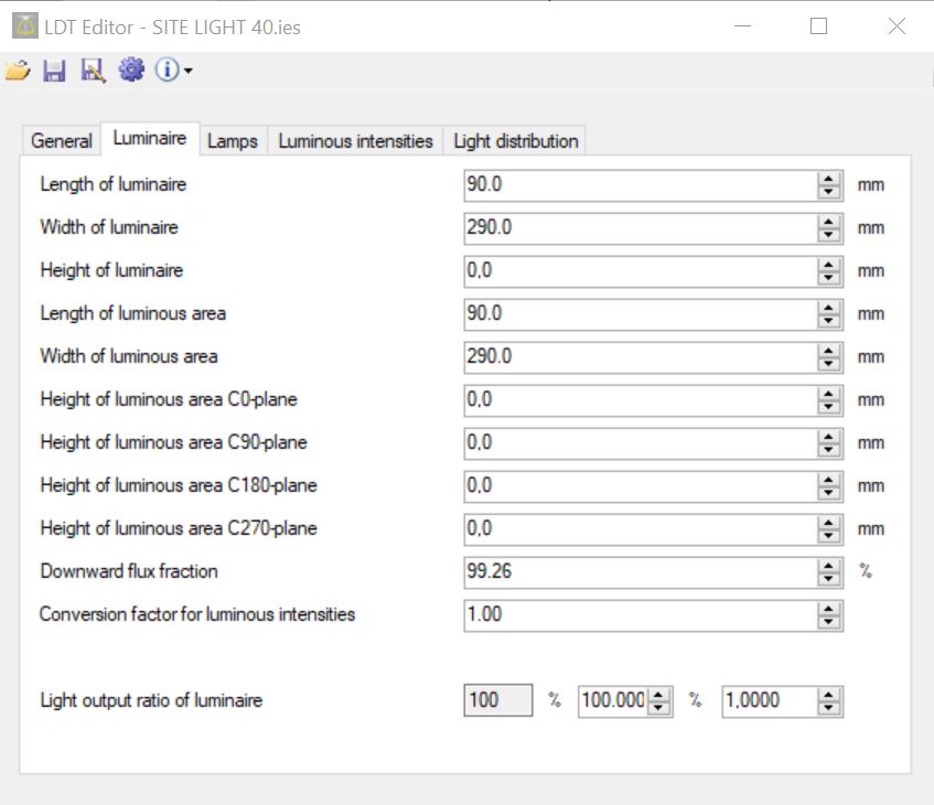
Working with Viso outputs in LDT Editor
Viso has decided generate both the .IES and .LDT files exactly as they are described in
the standards/definitions.

However, DIAL switches the terms for width and length in their software LDT Editor
– a free-to-use viewer.

An entry like the above in Viso Light Inspector can be exported correctly to .IES and
.LDT – still, when opening these files in LDT Editor length and width are exchanged:

When importing Viso .IES/.LDT files to DIAL Software DIALux Evo and DIALux 4.13 the
length/width parameters are right.

                                                                                    5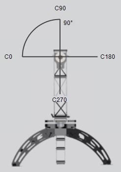
EULUMDAT - .LDT file format specification

    Item   Designation                                                    Number of
                                                                          Characters
     1     Company identification/data bank/version/format                 Max. 78
           identification max.
     2     Type indicator Ityp                                             1
           1 - point source with symmetry about the vertical axis
           2 - linear luminaire;
           3 - point source with any other symmetry [See Note 1]
     3     Symmetry indicator Isym                                         1
           0 - no symmetry
           1 - symmetry about the vertical axis
           2- symmetry to plane C0-C180
           3- symmetry to plane C90-C270
           4- symmetry to plane C0-C180 and to plane C90-C270
     4     Number Mc of C-planes between 0 and 360 degrees                 2
           (usually 24 for interior, 36 for road lighting luminaires)
     5     Distance Dc between C-planes (in degrees)                       5
           (Dc = 0 for non-equidistantly available C-planes)
     6     Number Ng of luminous intensities in each C-plane (usually      2
           19 or 37)
     7     Distance Dg between luminous intensities per C-plane            5
           Dg = 0 for non-equidistantly available lumin. intensities in
           C-planes
     8     Measurement report number                                       Max. 78
     9     Luminaire name                                                  Max. 78
     10    Luminaire number                                                Max. 78
     11    File name                                                       8
     12    Date/user                                                       Max. 78
     13    Length/diameter of luminaire (mm)                               4
     14    Width of luminaire b (mm) (b = 0 for circular luminaire)        4
     15    Height of luminaire (mm)                                        4
     16    Length/diameter of luminous area (mm)                           4
     17    Width of luminous area b1 (mm)                                  4
           (b1 = 0 for circular luminous area of luminaire)
     18    Height of luminous area C0-plane (mm)                           4
     19    Height of luminous area C90-plane (mm)                          4
     20    Height of luminous area C180-plane (mm)                         4
     21    Height of luminous area C270-plane (mm)                         4
     22    Downward flux fraction DFF (%)                                  4
     23    Light output ratio luminaire LORL (%)                           4
     24    Conversion factor for luminous intensities (depending on        6
           measurement)
     25    Tilt of luminaire during measurement (road lighting             6
           luminaires)
     26    Number n of standard sets of lamps                              4
           (optional, also extendable on company-specific basis)
     26a   Number of lamps                                                 n*4
     26b   Type of lamps                                                   n * 24
     26c   Total luminous flux of lamps (lumens)                           n * 12
     26d   Color appearance / color temperature of lamps                   n * 16
     26e   Color rendering group / color rendering index                   n*6

6
26f Wattage including ballast (watts) n*8
27 Direct ratios DR for room indices k = 0.6 ... 5 (for 10 * 7
determination of luminaire numbers according to
utilization factor method)
28 Angles C (beginning with 0 degrees) Mc * 6
29 Angles G (beginning with 0 degrees) – γ-angles Ng * 6
30 Luminous intensity distribution (candela / 1000 lumens) (Mc2-Mc1+1) *
[See Note 2] Ng * 6
NOTES
1. Only linear luminaires (Ityp = 2) are being subdivided in longitudinal and
transverse directions.
2. The parameters Mc1 and Mc2 for the luminous intensity distribution are
determined by:
Isym Mc1 Mc2
0 1 Mc
1 1 1
2 1 Mc / 2 + 1
3 3 * Mc / 4 + 1 Mc1 + Mc / 2
4 1 Mc / 4 + 1
3. Each field is an ASCII string that is terminated with an MS-DOS pair.
7.IES file format specification
Item Mandatory Designation VISO
1 IESNA-LM-63-2002 *
2 * [TEST] Test report no *
3 * [TESTLAB] Photometric testing laboratory *
4 [TESTDATE] Date that the photometric report was generated
5 [NEARFIELD] D1,D2,D3 Indicates near field goniophotometry
was used, D1,D2,D3 being specific distances – more info in
LM-63-2002
6 * [MANUFAC] Manufacturer of luminaire *
7 [LUMCAT] Luminaire catalogue number *
8 [LUMINAIRE] Luminaire description *
9 [LAMPCAT] Lamp catalogue number
10 [LAMP] Lamp description (e.g., type, wattage, size, etc.)
11 [BALLAST] Ballast description (e.g., watts, volts, magnetic or
electronic, etc.)
12 [BALLASTCAT] Ballast catalogue number
13 [MAINTCAT] A digit (1-6) indication IES maintenance
category
14 [DISTRIBUTION] General description of the light distribution
(e.g., Type II, Medium; Direct, etc.)
15 [FLASHAREA] Light emitting area of the medium projected
under 76 degrees in square meters. Used in calculation of
CIE glare control
16 [COLORCONSTANT] Used in calculations of CIE Glare Control
17 [LAMPPOSITION] Two angles that specify the lamp position
in the luminaire with respect to the photometric angles
18 * [ISSUEDATE] Date that the manufacturer issued the IESNA *
LM-63-2002 photometric file
19 [OTHER] Other information about this file
20 [SEARCH] User created search string
21 * [MORE] More information tied to previous keyword– in VISO *
[_SERIALNUMBER] =Viso Tracking no.
22 * TILT (TILT=NONE or TILT=INCLUDE or TILT=) This *
line indicates whether the lamp output varies as a function
of the luminaire tilt angle – more info in LM-63-2002
23a * Indicates number of lamps *
23b * The initial rated lumens for the lamp used in the test or -1 if *
absolute photometry is used and the intensity values do not
depend on different lamp ratings.
23c * A multiplying factor for all the candela values in the file. This *
makes it possible to easily scale all the candela values in the
file when the measuring device operates in unusual units—
for example, when you obtain the photometric values from
a catalog using a ruler on a goniometric diagram.
Normally the multiplying factor is 1.
23d * The number of vertical angles in the photometric web (no. *
of c-planes)
23e * The number of horizontal angles in the photometric web *
(no. γ-steps)
23f * Photometer type – 1 is Type C, 2 is Type B, 3 is Type C *
23g * The type of unit used to measure the dimensions of the *
luminous opening. Use 1 for feet or 2 for meters.
823h * The width, length, and height of the luminous opening. *
Length is measured parallel to horizontal angles 0°-180° = C0
– C180
Width is measured parallel to horizontal angles 90°-270° =
C90 – C270
24 * Luminous shape (if other than rectangular) – more info in *
LM-63-2002.
First number is width (alternatively -diameter)
Second number is length (alternatively -diameter)
Third number is height (alternatively -diameter)
25 * The set of vertical angles, listed in increasing order. If the *
distribution lies completely in the bottom hemisphere, the
first and last angles must be 0° and 90°, respectively. If the
distribution lies completely in the top hemisphere, the first
and last angles must be 90° and 180°, respectively.
Otherwise, they must be 0° and 180°, respectively.
26 * The set of horizontal angles, listed in increasing order. The *
first angle must be 0°. The last angle determines the
degree of lateral symmetry displayed by the intensity
distribution. If it is 0°, the distribution is axially symmetric.
If it is 90°, the distribution is symmetric in each quadrant.
If it is 180°, the distribution is symmetric about a vertical
plane. If it is greater than 180° and less than or equal to
360°, the distribution exhibits no lateral symmetries. All
other values are invalid.
27 * The set of candela values. First, all the candela values *
corresponding to the first horizontal angle are listed,
starting with the value corresponding to the smallest
vertical angle and moving up the associated vertical plane.
Then, the candela values corresponding to the vertical
plane through the second horizontal angle are listed, and
so on until the last horizontal angle. Each vertical slice of
values must start on a new line. Long lines may be broken
between values as needed by following the instructions
given earlier.
9You can also read