HERA-BD Type Series Booklet - Knife Gate Valve - KSB Web-Shop
←
→
Page content transcription
If your browser does not render page correctly, please read the page content below
Knife Gate Valve

HERA-BD

Type Series Booklet
Legal information/Copyright
Type Series Booklet HERA-BD

All rights reserved. The contents provided herein must neither be distributed, copied, reproduced,
edited or processed for any other purpose, nor otherwise transmitted, published or made available to a
third party without the manufacturer's express written consent.
Subject to technical modification without prior notice.

© KSB SE & Co. KGaA, Frankenthal 03/03/2021
Contents

Contents
Knife Gate Valves.............................................................................................................................................. 4
    Bi-directional Knife Gate Valve .................................................................................................................................................             4
        HERA-BD ...............................................................................................................................................................................   4
            Main applications...........................................................................................................................................................          4
            Fluids handled ................................................................................................................................................................       4
            Operating data...............................................................................................................................................................         4
            Valve body materials......................................................................................................................................................            4
            Design details .................................................................................................................................................................      4
            Product benefits .............................................................................................................................................................        4
            Product information ......................................................................................................................................................            5
            Related documents ........................................................................................................................................................            5
            Purchase order specifications ........................................................................................................................................                5
            Pressure/temperature ratings ........................................................................................................................................                 5
            Materials .........................................................................................................................................................................   6
            Variants...........................................................................................................................................................................   7
            Dimensions and weights................................................................................................................................................                8
            Installation information.................................................................................................................................................             9

                                                                                                                                                                                                  3
Knife Gate Valves
Bi-directional Knife Gate Valve
Knife Gate Valves Operating data
Operating properties
Bi-directional Knife Gate Valve
Characteristic Value
Nominal pressure PN 10
HERA-BD Nominal size
Max. permissible pressure [bar]
DN 50 - 1200
10
Min. permissible temperature [°C] ≥ -10
Max. permissible temperature [°C] ≤ +120
Valve body materials
Overview of available materials
Material Material number Temperature limit
EN-GJS-400-15 5.3106 ≤ 120 °C
Design details
Design
▪ Wafer-type design: suitable for clamping between pipe
flanges or dead-end service at full operating pressure
▪ Single-piece (≤ DN 500) or two-piece (> DN 500) body with
integrated flange seal
▪ Short face-to-face length to EN 558-1/20
Main applications ▪ Non-rising stem
▪ Waste water treatment plants ▪ Non-rising handwheel
▪ Biogas plants ▪ Blade made of 1.4571 as standard (≤ DN 400)
▪ Solids transport ▪ Confined U-shaped seal made of EPDM
▪ Water treatment ▪ Transverse seal with gland packing
▪ Paper industry / pulp industry ▪ Robust yoke for actuator mounting as standard
▪ Drainage systems ▪ All steel parts and cast iron parts epoxy-coated (200 µm) to
protect against corrosion, colour: RAL 5015, blue
▪ Drainage
▪ Washing plants Variants
▪ Sludge disposal ▪ Blade made of 1.4571 / AISI 316 Ti (≥ DN 450)
▪ Sludge processing ▪ Stem made of 1.4571 / AISI 316 Ti
▪ Food industry / beverage industry ▪ Nuts and bolts made of A4
▪ Sealing material made of NBR or Viton (U-shaped seal and
O-rings)
Fluids handled
▪ Gland packing made of stainless steel braiding, with
▪ Waste water with/without faeces scraper effect
▪ Activated sludge ▪ Chain wheel ≤ DN 600
▪ Service water ▪ Quick-action lever ≤ DN 150
▪ Digested sludge ▪ Gearbox ≥ DN 400
▪ Solids-laden fluids ▪ Double-acting pneumatic actuators ≤ DN 800
▪ River water, lake water and groundwater ▪ Electric actuators ≤ DN 1200 (with rising stem)
▪ Raw sludge ▪ Limit switch(es)
▪ Waste water ▪ Solenoid valves to NAMUR
7328.1/13-EN
▪ Other fluids on request. ▪ 3.1 certificate
▪ Larger nominal sizes and other variants on request
Product benefits
▪ All cast iron and steel components are protected against
corrosion by high-quality epoxy coating.
4 HERA-BDKnife Gate Valves
Bi-directional Knife Gate Valve
▪ Robust and compact steel yoke for straightforward Product information as per Pressure Equipment
mounting of pneumatic and electric actuators and Directive 2014/68/EU (PED)
position switches. A hard anodised aluminium NAMUR
The valves satisfy the safety requirements of Annex I of the
adapter plate attached to the actuator allows sensors or
European Pressure Equipment Directive 2014/68/EU (PED) for
solenoid valves to be quickly installed (plug & run).
fluids in Groups 1 and 2.
▪ Reliable and service-friendly stem seal: The gland packing
is made of PTFE impregnated fibre and can be re-adjusted
during operation. There is no need to remove the valve Product information as per Directive 2014/34/EU (ATEX)
from the piping to replace the packing.
The valves do not have a potential internal source of ignition
▪ High functional reliability and tight shut-off in both flow and can be used in potentially explosive atmospheres, Group II,
directions category 2 (zones 1+21) and category 3 (zones 2+22) to
– The stainless steel blade is polished on both sides and ATEX 2014/34/EU.
guided by a confined U-shaped seal during the entire
valve travel. This prevents "chattering" of the blade
and minimises the risk of deposits. Related documents
– Flushing corners in the body ensure the seat is flushed
clean when the valve closes. Information/documents
▪ Suitable for universal use. Flange connection via tapped Document Reference number
blind holes and throughbolts enables the wafer-type knife Technical data sheet 7328.22
gate valve to be clamped between pipe flanges or used as
dead-end valve at full operating pressure. Operating manual 7328.8
▪ Economically efficient
– The valve is available in a single-piece or two-piece Purchase order specifications
body design with full bore providing unrestricted
flow passage. The body is fully machined inside, Please specify the following information in all enquiries or
resulting in a tight fit of all components, very low purchase orders:
pressure losses and high flow coefficients. 1. Type
– As a standard feature, O-rings are integrated into the
2. Nominal pressure
body and serve as flange seals. This helps to save
extra costs for providing and fitting external flange 3. Nominal size
seals.
4. Operating pressure
5. Operating temperature
Product information 6. Fluid handled
7. Variants
Product information as per Regulation No. 8. Reference number
1907/2006 (REACH)
For information as per chemicals Regulation (EC) No 1907/2006
(REACH), see http://www.ksb.com/reach.
Pressure/temperature ratings
Test pressure and operating pressure
PN DN Shell test Leak test (seat) Permissible operating pressure
With water
Tests P10 and P11 to Test P12 to DIN EN 12266-11) -10 to +120 °C
DIN EN 12266-1
[bar] [bar] [bar]
10 50 - 250 15 11 10
6 300 - 400 9 6,6 6
5 450 7,5 5,5 5
4 500 - 600 6 4,4 4
2 700 - 1200 3 2,2 2
7328.1/13-EN
1 DN 50 - 600: leakage rate A, DN 700-1200: leakage rate B
HERA-BD 5Knife Gate Valves
Bi-directional Knife Gate Valve
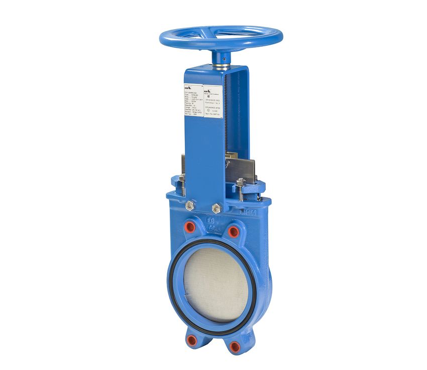
Materials
Fig. 1: Sectional drawing
Overview of available materials
Part No. Description Material Material number Note
100 Body EN-GJS-400-15 5.3106 DN 50 - 500: epoxy-coated, single-
piece
DN 600: epoxy-coated, two-piece
166 Yoke Steel 1.0044 / S275JR Epoxy-coated
200 Stem Stainless steel 1.4016 / AISI 430 Non-rising
360 Blade Stainless steel 1.4571 / AISI 316 Ti DN 50 - 400
Stainless steel 1.4301 / AISI 304 ≥ DN 450
410 U-shaped seal EPDM with steel core - -
412.1 O-ring EPDM - Integrated flange seal
412.2 O-ring EPDM - -
452 Gland follower EN-GJS-400-15 5.3106 Epoxy-coated
461 Gland packing PTFE-impregnated - -
synthetic fibres
540 Bush Stainless steel 1.4301 / AISI 304 -
544 Threaded bush Brass - -
547 Guide bush Manganese bronze C86300 / CB762S -
556 Anti-friction disc PET + solid lubricant - -
562 Spring-type straight Steel DIN 7346 -
pin
901 Hexagon head bolt A2 - -
902 Stud A2 - -
920 Hexagon nut A2 - -
961 Handwheel Steel - DN 50 - 300: epoxy-coated
EN-GJS-400-15 5.3106 ≥ DN 350: epoxy-coated
7328.1/13-EN
6 HERA-BDKnife Gate Valves
Bi-directional Knife Gate Valve
Variants
Chain wheel (non-rising stem) Quick-action lever
Gearbox (non-rising stem) Pneumatic actuators Electric actuators
(double-acting) (rising stem)
7328.1/13-EN
HERA-BD 7Knife Gate Valves
Bi-directional Knife Gate Valve
Dimensions and weights
øk øk øk
DN 50-65 DN 80-200 DN 250-300
øk øk
øk
DN 350-400 DN 450-500 DN 600
øk øk øk
DN 700-800 DN 900-1000 DN 1200
Fig. 2: Sectional drawing
Dimensions and weights
PN DN l h1 B ød [kg]
[mm] [mm] [mm] [mm]
10 50 43 312 113 225 8
65 46 339 128 225 9
80 46 364 143 225 10
100 52 405 162 225 12
125 56 439 181 225 15
150 56 485 209 225 17
200 60 595 263 310 30
250 68 695 315 310 42
6 300 78 785 370 310 60
350 78 932 420 410 90
400 102 1017 478 410 140
5 450 114 1119 532 550 185
4 500 127 1219 584 550 204
600 110 1379 762 550 230
2 700 110 1736 890 800 380
800 110 1923 1012 800 550
900 110 2047 1112 800 680
1000 110 2487 1240 800 800
Dimensions [mm]
PN DN øk Number of Bolt size Blind hole Tapped blind holes Clearance holes2) Tapped holes3)
bolt holes ø M depth n1 n2 n3
z T
7328.1/13-EN
[mm] Qty [mm] Qty Qty Qty
10 50 125 4 M16 10 4 0 0
65 145 4 M16 10 4 0 0
80 160 8 M16 12 4 4 0
100 180 8 M16 12 4 4 0
125 210 8 M16 14 4 4 0
2 Bolts passing along the side of the body
3 Tapped from both ends, not through-tapped
8 HERA-BDKnife Gate Valves
Bi-directional Knife Gate Valve
PN DN øk Number of Bolt size Blind hole Tapped blind holes Clearance holes2) Tapped holes3)
bolt holes ø M depth n1 n2 n3
z T
[mm] Qty [mm] Qty Qty Qty
10 150 240 8 M20 14 4 4 0
200 295 8 M20 14 4 4 0
250 350 12 M20 18 8 4 0
6 300 400 12 M20 21 8 4 0
350 460 16 M20 21 6 4 6
400 515 16 M24 28 6 4 6
5 450 565 20 M24 30 12 4 4
4 500 620 20 M24 40 8 4 8
600 725 20 M27 26 12 8 0
2 700 840 24 M27 20 16 8 0
800 950 24 M30 20 16 8 0
900 1050 28 M30 20 20 8 0
1000 1160 28 M33 20 20 8 0
Mating dimensions as per standard
Face-to-face lengths: EN 558-1/20 up to DN 500
≥ DN 600: see table
Flanges: DIN EN 1092-2
Other flange designs
▪ Other flange designs on request
Installation information
HERA BD is bi-directional, i.e. flow may pass the valve in either
direction. Installation as dead-end valve at full operating
pressure without counterflange is permissible. Observe the
maximum operating pressures for the respective nominal sizes.
Due to the O-rings integrated into the flange faces no further
flange seals are required.
7328.1/13-EN
HERA-BD 903/03/2021
7328.1/13-EN
KSB SE & Co. KGaA
Johann-Klein-Straße 9 • 67227 Frankenthal (Germany)
Tel. +49 6233 86-0
www.ksb.comYou can also read