Hi-Velocity Systems RPM-E Cooling Installation - Manufactured By - Small Duct Heating, Cooling
←
→
Page content transcription
If your browser does not render page correctly, please read the page content below
TM

       Small Duct Heating, Cooling and
         Indoor Air Quality Systems

     www.hi-velocity.com

  Hi-Velocity Systems
RPM-E Cooling Installation

             Manufactured By

                              Module-RPM-RPM-E-Cooling-Installation-052813
Module RPM
                                                                                             Refrigerant Module Installation (RPM-E) (1/5)
                                                             www.hi-velocity.com

     Refrigerant Modules (RPM-E)                                             Fig. RPM-01 - RPM-E Cooling Module Configurations

                                                                                             B1

   The RPM-E series cooling module can be used with the Hi-

                                                                                        CO
Velocity Fancoil, installed in many different positions. It is pre-             A                               B
piped with an adjustable, heat pump ready, thermal expansion

                                                                                           IL
valve and comes with a bleed port, sight glass, suction and liquid
line access ports, freeze-stat, and two L brackets for mounting.
    The RPM-E comes as a complete module and must be installed
 in the vertical position on the return air side of the fancoil; the                         A1
 unit cannot be turned on its side and is a draw through unit
 only. The module offers multi-position airflow configurations             Rough Opening Sizes               A or B                  A1 or B1
 for horizontal, highboy, or counter-flow configurations. (Fig.
                                                                            RPM-E 50                 113/4”L X 131/4”H             113/4”L X 9”W
 RPM-01)                                                                                              (298mm X 337mm)              (298mm X 229mm)
   The TXV (Thermal Expansion Valve), sight glass, access                                            16 ”L X 13 ”H
                                                                                                       3/4          1/4
                                                                                                                                   163/4”L X 9”W
                                                                            RPM-E-70
ports, and freeze-stat* are already installed and are accessible                                      (425mm X 337mm)              (425mm X 229mm)

through an easy to remove access hatch. The liquid and suction              RPM-E-100                223/4”L X 131/4”H             223/4”L X 9”W
                                                                                                      (578mm X 337mm)              (578mm X 229mm)
lines have male solder connections at a standard width making
connections to the condenser lines quick and easy.                                     RPM-E Drain Pan Extension
 *IMPORTANT: The freeze control serves the                                The RPM-E Drain Pan Extension (DPE) is to be removed for
 purpose of preventing severe icing of the coil in the                  up flow (vertical) return air applications (avoid installing the
 event of an undercharge or low load on the coil. This                  RPM-E in counter flow applications).
 piece of equipment must be used at all times. Lack
 of use of the freeze-stat will result in RPM-E related                    To remove the pre-installed DPE, first remove left side access
 warranty issues being voided.                                          panel of the RPM-E Module. Remove the 3 - ¼ ” screws
                                                                        that hold the DPE in place, remove the DPE and replace ¼”
                         Configurations                                 screws into the coil support (Fig. RPM-02). Replace the left
    When installing, follow the recommendations shown in                side access panel.
 Table 01, demonstrated in Fig. 01. For example, a horizontal
 application could use A to B while highboy applications could
 use A to B1. Do not use a combination of A to A1 or B to B1,
 as this would bypass the cooling coil completely. A1 is not
 to be used for outlet airflow. The knock-outs can be removed
 with a screw driver and hammer. Use caution when opening
 the knock-outs, ensuring you do not damage the coil surface.
                                                                                            Fig-RPM-02 - Remove DPE
        Table RPM-01 - RPM-E Cooling Module Configurations
                                                                         The lower knockout can now be removed, using a screwdriver
               Right                        Wrong
                                                                       and hammer (Fig-RPM-03). Use caution when removing
               A to B                       B1 to A1
                                                                       knockouts ensuring you do not damage the coil inside the
               A to B1                      B to A1
                                                                       module.
              A1 to B                       A to A1
              A1 to B1                      B to B1
               B to A*
              B1 to A*

 *B to A and B1 to A configurations are not recommended,
 due to a higher chance of carry-over issues.
 Important: If side A1 is going to be used in your selected
                                                                                          Fig-RPM-03 - Remove Knockout
 configuration, the extended drain pan must be removed.
                                   Module RPM Refrigerant Module Installation (RPM-E) (1/5)
                                                                                                                          © 1995-2013
                                                                                                                            1995-2009 Energy Saving Products Ltd.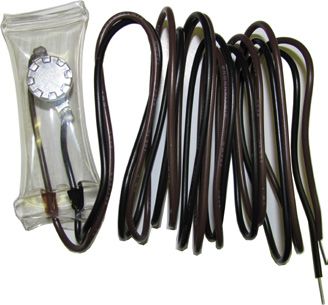
Module RPM
                                                                                            Refrigerant Module Installation (RPM-E) (2/5)
                                                          www.hi-velocity.com

                                                                                       Fig. RPM-05 - Secondary drain pan
                 Mounting the RPM-E
   Two L mounting brackets are shipped loose for attaching the
RPM-E to the fancoil, along with two sided foam tape for an
air seal between the units. When mounting the cooling coil to
the fancoil (Fig. RPM-04), ensure that no screws puncture the
drain pan or coil. It is advised that no screws be placed within
3 inches (76mm) from the bottom of the coil. This will prevent
the drain pan from being accidentally pierced. It is also advised
that care be taken when placing screws in the top left side of
the cooling coil (when looking at the access hatch), as this is
where the top most extent of the cooling coil is located. See                                                   P-Trap
Specification Pages for the dimensions of the fan coil units and
                                                                                               Secondary drain pan
cooling modules.

                                                                                           Drain Connections
                                                                         All RPM-E modules come with a ¾” (19mm) primary and
                                                                      secondary outlet. The condensate drain must have a vented p-trap
               Fig. RPM-04 - Mounting Brackets
                                                                      installed (Fig. RPM-05), and run at a slope of ¼” (6.7mm) per
                                                                      foot in the direction of the drain. When installing the P-trap, one
                                                                      must be installed on both the primary and secondary outlets. The
                                                                      P-traps must have a minimum depth of two inches (51mm). Due
                                                                      to the high negative pressure of the blower system, the RPM-E
                                                                      will hold some amount of water during operation. Once this level
                                                                      has been achieved, condensate will flow from the coil regularly.
                                                                      When the unit shuts down, or lowers speed, the force is released,
                                                                      allowing the held condensate to empty from the drain pan.
                                                                      During this time, condensate may flow from both the primary
                                                                      AND secondary drains.
                                  (76mm)

  (76mm)                                                                              Outdoor Unit Installation
                                                                         Locate the outdoor unit in a suitable location, as close as
                                                                      possible to the fan coil. Maintain the clearances recommended by
                                                                      the manufacturers of the outdoor unit, to ensure proper airflow.
                                                                      The outdoor unit must be installed level, in a properly supported
                                                                      location. A liquid line filter/drier is recommended to be installed.

                  Secondary Drain Pan                                                   Wiring - Outdoor Unit
                                                                         Make all connections to the outdoor unit with rain tight conduit
   Some building codes call for the use of a secondary drain pan      and fittings. Most building codes require a rain tight disconnect
underneath the entire unit (Fig. RPM-05). Any installation that       switch at the outdoor unit as well (always check local codes).
has the potential of property damage due to condensate must           Run the proper size copper wires to the unit, and connect as per
have a secondary drain pan installed. If the unit is installed in a   the manufacturer’s recommendations.
high heat and/or high humidity location, extra insulation around
                                                                        Ensure that the outdoor unit is setup for a TX system. If not, a
the unit casing may be required. This will prevent excessive
                                                                      hard start kit may be required.
condensate from forming on the outer surface of the casing.

                                 Module RPM Refrigerant Module Installation (RPM-E) (2/5)
                                                                                                                 © 1995-2009 Energy Saving Products Ltd.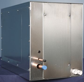
Module RPM
                                                                                             Refrigerant Module Installation (RPM-E) (3/5)
                                                            www.hi-velocity.com

                                                                                   Fig. RPM-06 - Remove Front Access Panel
                          Pipe Sizing

    When sizing refrigerant piping, follow
      the outdoor unit manufacturer’s
             recommendations.

                     Piping the RPM-E
    Only refrigerant grade pipe and fittings are to be used with
Hi-Velocity Systems. Plumbing fittings may contain wax or other           Once the system has been brazed it must be pressure tested.
contaminants which are detrimental to the proper operation of          Pressure testing must be done with nitrogen and not refrigerant.
the system. Insulate the suction line with 3/8” (9.53mm) insulation    Typically, pressures are tested to the maximum operating pressure
such as Armaflex. In high heat areas, 1/2” (12.7mm) insulation         that the system will see. Allow the system to hold the nitrogen
may be needed. If the lines are run in an area where temperatures      charge for at least 15 minutes to ensure there are no leaks. Check
could exceed 120°F (49°C) or runs longer than 50’ (15.24m), then       with local codes for proper testing procedures.
the liquid line may need to be insulated as well. Support the pipe
every 5 feet (1.52m), or whatever local code states.
                                                                                                 Evacuating
   Run the pipes in the most direct route possible, taking into
account structural integrity and building details. If the evaporator      After the piping is installed and all components have been
is located above the condenser, slope any horizontal runs toward       brazed together, a vacuum pump must be used to evacuate the
the condenser. If the condenser is located above the evaporator,       system from both the low and high side to 1500 microns (200
a P-trap must be installed at the bottom of the vertical riser. For    pa). Add pressure to the system to bring the pressure above zero
long vertical risers, additional P-traps must be installed for every   psig. After allowing the refrigerant to absorb moisture, repeat the
twenty feet (6m). For lines running over 50’ (15m), a suction line     above procedure. Evacuate the system to 500 microns (67 pa) on
accumulator must be installed. Lines running over 100’ (30m) are       the second evacuation, and ensure that the system holds at the
not recommended. All lines should be piped so as not to restrict       vacuum pressure. If not, check for leaks and evacuate again. At
access to the front panels, filter section, or electrical enclosure.   this point open service valves on pre-charged condensing units,
                                                                       and add refrigerant to the system if necessary.

                                                                        The use of an electronic leak detector is recommended, as it is
                                                                       more sensitive to small leaks under the low pressures.

              Brazing & Pressure Testing                                                          Charging
   The RPM-E comes pre-piped with the coil assembly. With the             Once the system has been determined clean and ready for
RPM-E, the Liquid and Suction lines are the only brazing that          charging, refrigerant can be added. The access ports on the
need to be done at the fan coil. For charging and brazing, remove      condenser must be open at this point. Never leave the system
the front access panel of the RPM-E (Fig. RPM-06). With the            unattended when charging. With the system running, slowly
access panel removed, the coil assembly will be accessible. Wet        add refrigerant. The typical operating point of an RPM-E coil
rag the liquid and suction line (or use a heat dissipating paste)      is that of a saturated suction temperature of 38-40°F (3-4°C)
to ensure no overheating occurs to the pre-piped coil assembly.        and a suction line temperature of 42-44°F (6-7°C). In order to
Excess heat may damage the RPM-E components.                           prevent overcharging during this stage, refrigerant should be
                                                                       added in steps. This will allow time for the system to settle and
                                                                       prevent ‘overshooting’ the ideal charge. Condenser pressures and
                                                                       temperatures remain similar to those in a conventional forced air
                                                                       system. It is recommended that the coil be charged on a high load
                                                                       day at the compressor’s highest speed.

                                  Module RPM Refrigerant Module Installation (RPM-E) (3/5)
                                                                                                                 © 1995-2009 Energy Saving Products Ltd.
Module RPM
Refrigerant Module Installation (RPM-E) (4/5)
www.hi-velocity.com
Charging Cont’d
Most system start ups require only an adjustment to the
The receiver is a horizontal tank with a pair of dip tubes
refrigerant level of the system. Should further refinement be
extending to the bottom of the tank. These two tubes allow for
required, the TXV may be adjusted. A clockwise turn of the
liquid refrigerant to be drawn from the tank regardless of the
superheat valve (the direction in which the cap is screwed on)
direction of flow. For this reason, the receiver must be mounted
will result in a closing of the valve while a counterclockwise
so that the inlet/outlets of the tank come out of the top of the unit.
turn (the direction in which the cap was unscrewed) will result
Mounting brackets are located at the base of the unit for secure
in opening of the valve. Always note system conditions before
mounting. The receiver is to be located on the liquid line of the
adjusting the valve and allow 5 minutes for the system to settle
system, anywhere between the indoor and outdoor coils. As the
before making any further adjustments. Never adjust the TXV
unit is of a bi-flow design, it does not matter which end faces
more than one quarter turn at a time.
towards the indoor coil.
The RPM-E coil can operate at a level that is different from
most other conventional system coils. Typically, superheat level The inlet/outlet ports are constructed of steel and require the
are low, two to four degrees of superheat. Adjustment of the valve use of a 35-45% Silver Solder and Flux for brazing. The use of
also differs somewhat. Rather than having a large effect on the standard copper to copper solders may result in difficulty brazing
range of superheat, adjustment of the valve has a larger effect and the potential for a failure at the weld. Ensure that the tank is
on the system pressures; superheat maintaining a fairly constant protected from overheating while brazing and that any remaining
point. Opening the valve will increase suction pressures and flux is cleaned from the unit. If installing outdoors, ensure that
decrease liquid pressures, while closing the valve will decrease the receiver is insulated and protected from the elements.
suction pressures and raise liquid pressures.
Heat Pumps
Traditionally, SDHV systems have been charged to special
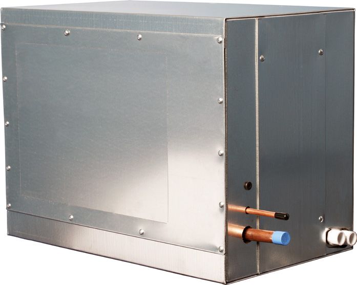
guidelines when used in conjunction with heat pumps. This Freeze Stat
charging procedure involved charging the units to normal
cooling capacities and reviewing the operation in heating mode.
If head pressures were found to be impinging on the high head
pressure limits, a small amount of refrigerant was removed to
prevent the unit from shutting down. The cause of high head
pressures in heating mode is due to the disparity in sizes of the
indoor and outdoor coils, along with the lower airflow rates of
SDHV systems.
With the introduction of newer, larger heat pumps, this issue The RPM-E series cooling coil comes equipped with an
is more likely to be experienced. While some heat pump units anti-freeze control mounted on the suction line. This freeze
may still be charged in the traditional method, the amount of control serves the purpose of preventing severe icing of the coil
refrigerant that is required to be removed for heating mode may in the event of an undercharge or low load on the coil. This
leave the system drastically undercharged for cooling mode. For piece of equipment must be used at all times. Lack of use
this reason it is highly recommended that a Bi-Flow Receiver be of the freeze-stat will result in RPM-E related warranty
used with heat pump applications. issues being voided. During start-up, it is acceptable to
jumper across the Freeze-Stat. This will prevent the freeze-
Bi-Flow Receiver
stat from shutting the system off while charging a new system
The Bi-Flow Receiver is designed for use with heat pump that may be low on refrigerant. Once charged and running,
systems, up to 5 tons, and with any typical refrigerants. The this jumper must be removed and the Freeze-Stat connected to
receiver allows refrigerant a location to migrate to during the the X1 and X2 terminals on the Printed Circuit Board. Should
heating cycle, minimizing head pressures. During cooling mode, wiring needs arise in which the outdoor unit is controlled
the receiver is empty, allowing the full refrigerant charge to be through another means of wiring, the Freeze-Stat should be
utilized for cooling. connected in series on the supply side of the control wiring.
Module RPM Refrigerant Module Installation (RPM-E) (4/5)
© 1995-2009 Energy Saving Products Ltd.Module RPM
Refrigerant Module Installation (RPM-E) (5/5)
www.hi-velocity.com
Troubleshooting the TXV
When issues arise that bring the function of the TXV into and outdoor unit, on and off. This often takes the form of very
question, factors must be looked into before replacement. Inspect short and frequent on cycles. There are many factors that may
the TXV for signs of damage. This may be from a pinched contribute to short cycling of the refrigerant system. These issues
equalizer line to a burnt valve. These issues will have an adverse can generally be broken down between airflow related issues,
affect on the operation of the valve. Should the equalizer line be refrigerant issues, and installation issues.
pinched, the valve will no longer be able to supply the proper Low airflow rates are one of the most common causes of short
amount of refrigerant to the coil. A burnt valve may have an cycling. As the airflow rate is lowered across the cooling coil,
effect on the refrigerant charge of the TXV bulb or the seal of the the coil pressure drops along with it. This lowers the temperature
valve. This may again cause an improper amount of refrigerant of the coil and may cause the freeze-stat to trip. As the system
to be metered by the valve or cause the valve head to become settles, the freeze-stat closes and the cycle begins again, as the
seized. unit does not run long enough for the space to become adequately
conditioned. Ensure that the proper amount of airflow is provided
The TXV bulb location and mounting should also be inspected.
to the coil. Check for proper air flows and return air practices.
The bulb should be securely mounted on the top half of the
suction line. If the bulb is loose or on the lower half of the line, Improperly charged systems run the risk of short cycling as
the bulb will not properly sense the refrigerant temperature and well. An undercharged system will react much the same as a
will not meter the proper amount of refrigerant. Ensure that the system with low airflow. If the charge is low enough, it may trip
bulb is also properly insulated, as a lack of insulation will expose out on low pressure. If a system is overcharged, it may trip out on
the bulb to conditions well outside those of the coil. This will high head pressure. Ensure that the system charge is within the
cause an overfeed of refrigerant to the system. bounds described in section “Piping the RPM-E”.
Should the installation of the valve be proper, and no damage
is evident, inspect the operation of the valve. If the TXV bulb System set-up and installation should be checked as well.
is removed and held in ones hand, the valve should react Piping practices should be within the bounds described in section
accordingly. This sudden increase in heat will open the valve. “Piping the RPM-E” and within the realms of the outdoor unit
This will cause a rise in suction pressure and a drop in liquid manufacturer. Extreme and often unnecessary adjustment of the
pressure. Should nothing happen, the valve is likely seized and TXV can create conditions similar to an undercharged coil. A
will need to be replaced. poorly placed T-stat, such as underneath a vent, can cause short
cycling. This happens due to the T-stat being satisfied very
Short Cycling
shortly after the unit has begun to operate.
Short cycling is the unnecessary running of the indoor
Specifications RPM-E-50 RPM-E-70 RPM-E-100
Matching Fan Coil HE-Z/HE/HV - 50 / 51 / 52 HE-Z/HE/HV - 70 / 71 HE-Z/HE/HV - 100 / 101
LV-50 LV-70 LV-120/140
Part Number 20090200050 20090200070 20090200100
Refrigerant Type R-410A R-410A R-410A
TX Cooling MBH1 18-24 (5.3-7.0 kW) 30-36 (8.8-10.6 kW) 42-60 (12.3-17.6 kW)
Latent Cooling MBH 6.8-8.9 (2.0-2.6 kW) 11.7-13.7 (3.4-4.0 kW) 16.0-22.2 (4.7-6.5 kW)
Fin Material Aluminum Aluminum Aluminum
Tubing Material Copper Copper Copper
Type of Fins .006 Al .006 Al .006 Al
Liquid Line (Lq) 3/8” (9.5mm) 3/8” (9.5mm) 3/8” (9.5mm)
Connection Sizes Suction Line (S) 7/8” (22.3mm) 7/8” (22.3mm) 7/8” (22.3mm)
Drain Connection 3/4” (19mm) 3/4” (19mm) 3/4” (19mm)
TXV with Built in Check Valve & Bypass Yes Yes Yes
Site Glass Yes Yes Yes
Access Ports Yes Yes Yes
Freeze Stat Yes Yes Yes
Shipping Weight (lbs) 48 (22kg) 59 (27kg) 74 (34kg)
Module Size (L x W x H) 191⁄4” x 145⁄8” x 181⁄2” 241⁄4” x 145⁄8” x 181⁄2” 32” x 145⁄8” x 181⁄2”
(489mm x 371mm x 470mm) (616mm x 371mm x 470mm) (813mm x 371mm x 470mm)
Tons 2
1.5 - 2.0 (5.3 - 7.0 Kw) 2.5 - 3.0 (8.8 - 10.6 Kw) 3.5 - 5.0 (12.3 - 17.6 Kw)
MBH = Thousand British Thermal Units per Hour TX = Thermal Expansion TXV = Thermal Expansion Valve
1) Smaller condensers may be matched to the fan coil when needed (match TXV to condenser size)
2) Minimum of 8 full 2” (51mm) outlets per ton of cooling needed (4 outlets for HE)
Module RPM Refrigerant Module Installation (RPM-E) (5/5)
© 1995-2013 Energy Saving Products Ltd.You can also read