Compaction of Radioactive Waste - www.nukemgroup.com
←
→
Page content transcription
If your browser does not render page correctly, please read the page content below
Compaction of
                     Radioactive Waste

www.nukemgroup.com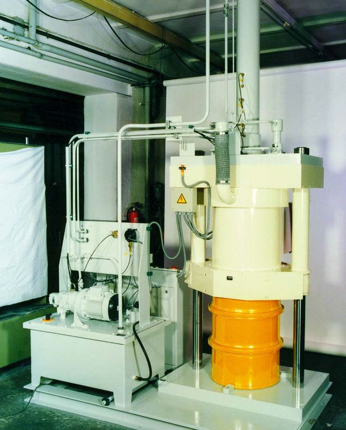
COMPACTION
OF RADIOACTIVE WASTE

Introduction
Low level dry active waste is one of       • high volume reduction ratios,
the main waste streams generated             small envelope dimensions
from the operation of nuclear power        • up to 20000 kN pressing force
plants or other nuclear facilities.        • special designs to match different
Waste of this type is usually                drum dimensions and materials
collected in drums or other                • compaction inside, an enclosed
containers. In order to save storage         volume of the compactor avoids
space and costs, it has to be treated        contamination of the environment
prior to disposal.                         • good maintainability and easy
Compaction can reduce the overall            decontamination
volume of drums containing solid           • mobile design possible
radioactive    material    and    the
                                           • well proven equipment
technology      is    well    proven.
NUKEM designs and supplies                 A special advantage of the NUKEM
compactors for the nuclear industry        design is that the upper external
that meet all the client’s needs to        surfaces of the units are not
achieve efficient and economic             encumbered by moving components.
volume reduction.                          This feature greatly simplifies
The advantages that can be gained          attaching an alpha containment and
by using the NUKEM compaction              also ensures that a minimal portion
technology directly influence the          of the press is installed within the
costs of storage and disposal.             contaminated zone. It also makes it
The NUKEM compaction technology            possible to design a mobile unit.
presents the following main features:

Pre-treatment of Waste and Waste Characteristics
The bulk of waste produced in              storage or disposal. Within limits, wet
nuclear facilities is low level, dry and   wastes can also be compacted.
either    combustible        or     non-   The following wastes can be
combustible. All of these waste            compacted:
streams can be treated by the
NUKEM compaction technology. A
pre-sorting stage is advisable and for
combustible        wastes,      NUKEM
recommends incineration as a pre-
treatment, since this can bring
additional benefits in terms of safety
and economy in subsequent

NUKEM Technologies GmbH                                                          1
2007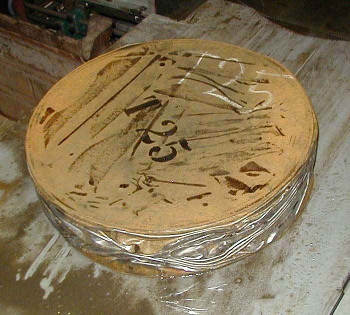
•   Scrap metal                             • Combustion residue (ash, slag)
    •   Construction materials                  • Mixed waste such as glass,
    •   Paper, wood, plastics                     worn parts, filters
    •   Elastic materials, such as              • Residue from waste water
        small amounts of rubber mixed             cleaning processes
        with other waste                        • Dry         filter    residue

Examples of typical volume reduction ratios obtained by employing a high
force compactor

          Waste type                                Ratio      Pellet
                                                              volume

          Mixed scrap metal                          6-7       ~15 %
          Chips from metal cutting operations        6-7       ~15 %
          Ashes from an incinerator                  2-3       ~40 %
          Insulation material (glass wool)           16         6.3 %
          Rubble (bricks, cement)                    2.2         45 %
          Sand                                       1.3         77 %
          Glass bottles                              5.2         28 %

The ratio achieved can be                   purposes only. For safe operation,
influenced considerably by the              certain limits, specific to the material
nature of the waste and the figures         to be compacted, should be
above are given for guidance                followed.

The NUKEM High Force Compactor Technology
The NUKEM        High Force Compactor (HFC) unit consists of the following
systems:

•   Main compactor body                    •    Liquids handling system
•   Drum in-feed system                    •    Switchgear for electrical      and
•   Pellet delivery system                      control equipment
•   Hydraulic power pack                   •    Control desk
•   Air, gas and particulate handling
    system

2                                                           NUKEM Technologies GmbH
                                                                                2007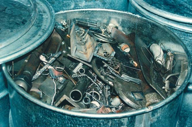
The design of the main compactor          into the steel structure, where the
body                                      two openings are located. The
The principal component of the com-       bolster is guided at all times within
pactor is a forged steel structure with   the     structure    by    replaceable
two openings, one for charging            bearings.
drums and one for discharging             The two doors are part of the
compacted pellets. The top section        standard press and are used to
forms the main high-pressure              isolate the compaction operation,
cylinder. The lid is fastened to the      thus restricting the spread of
steel structure and rigidly supports      airborne particles. They are not used
the guiding rod. The main piston          if the unit is located in an area
provides the high pressure/low            without direct man access.
speed capability while the guiding        Certain components, e.g. the bolster
rod provides the low pressure/high        liner, and the platens (top, bottom)
speed characteristics. The four           are designed to be replaced in the
external hydraulic cylinders serve to     event that they wear during the
return the main piston to the upper       lifetime of the system.
position. The heavy bolster, or           An exhaust opening is provided in
mould, is employed to absorb the          one door for the safe release of
high radial loads generated during        gases and particulate, produced
the drum compaction process and           during the process. In the other door,
avoids transmitting these radial loads    an air inlet damper is provided.

Fig. 1 High Force Compactor – Main Compactor Body

NUKEM Technologies GmbH                                                        3
2007
Drum infeed system                      All components are fitted into or onto
The drums are loaded into the press     the steel tank, except for the
via the infeed system, which is         hydraulic pump. The unit is installed
directly attached to the main           on anti-vibration mountings.
compactor       body.    The     main
components are the base unit, the       Gas and particulates handling
loading plate, the drum centering       system
device, and the perforating device.     In our standard design, the air or gas
The loading plate provides the trans-   with particulates displaced during the
portation capabilities while the        compaction process is directed to the
perforating device performs a pre       compactor chamber outlet, via a
compaction treatment.                   class S particle filter which is located
The operating sequences of the high     in one of the doors. If required, a
force compactor are coordinated         direct connection to an existing
from and with the control equipment     ventilation system is possible, if
of the high force compactor.            necessary with supporting ventilation
                                        equipment (e.g. fan, filter). For clean
Pellet delivery system                  air, an air inlet damper is located in
The pellets are ejected from the        the door on the opposite side.
compactor by the loading plate. The
pellet delivery system provides the     Liquids handling system
platform for additional steps e.g.      Bulk liquids should be removed from
measuring of height and weight.         the debris prior to compaction.
These are optional. The pellet          However, any residual liquids
delivery system consists of the base    extracted from the drum are
frame and the transfer plate.           collected by a ring-shaped drain in
                                        the lower part of the system, that
Hydraulic power pack                    feeds to a tank for temporary
The hydraulic power pack unit was       storage.
especially designed for ease of main-
tainance and low space requirement.     Control and electrical equipment
Generally it is located in a separate   The switchgear system consists of
room.                                   • a cubicle for the electrical and
The main components are:                    control equipment and
• Cubical steel tank with a welded      • a control desk.
    lid                                 In order to satisfy the different
• Immersed hydraulic pump in "on        requirements of the compactor, a
    line" design with regulated high    programmable control system (SPS)
    pressure stage                      coordinates the process. The
• Switchgear                            individual steps are monitored from
• Oil cooler with cooling water         the control desk. The operating
    connections                         conditions are displayed on the
• Immersed heater                       control panel of the desk. Any
• Oil filter                            deviation from the correct operating
• Tank vent with filter                 conditions    triggers  an     alarm.
• Oil filling flange with filter.       Depending on the type of deviation, it
                                        is     corrected      manually     or
                                        automatically.

4                                                       NUKEM Technologies GmbH
                                                                            2007
Two modes of operation are               plate is retracted. The drum placed
possible:                                on the bottom platen and held in
• Automatic operation                    position by the bolster.
   This is the standard mode. The        Step 4: Compacting process
   compaction process is performed       The bolster and the doors are
   automatically.                        closed. This lowest end position
• Manual operation                       ensures a complete enclosure of the
   Manual operation is possible and      drum. The guiding rod is pressurized
   is provided only for setting-up,      and the main piston moves down
   maintenance and repair purposes       rapidly onto the drum and starts the
   and the repeating tests.              first part of the compacting process.
                                         At the same time, the main piston is
                                         filled with hydraulic fluid. When
                                         completed, the pressure in the main
                                         piston chamber and in the guiding
The Operational Steps of                 rod      chamber       is    increased,
Compaction                               compacting the drum into a pellet.
Step 1: Loading the drum                 After reaching a pre-set value, this
The drum is transferred to the drum      pressure is maintained for a defined
infeed system with a crane. The          period of time in order to maximize
drum centering device positions and      the compaction ratio.
aligns the drum on the loading plate.    Step 5: Pellet removal
The HFC is at the start position: The    After the pressure is reduced, the
bell-shaped bolster and the main         compacted drum (i.e. the pellet), is
piston are at the upper position. The    ejected from the bell shaped bolster.
doors are open.                          During this removal stage, the main
Step     2:    Preparation      before   piston remains at its lower stop
compaction                               position, while the bolster is raised to
The drum is perforated and is moved      its upper stop position. Next, the
to the center of the main compactor      doors open and the main piston
body below the bolster. Both steps       returns to its upper stop position.
are again performed by the drum          When inserting a new drum, the
infeed system.                           loading plate of the drum infeed
Step      3:     Positioning       for   system ejects the pellet from the
compaction                               bottom platen onto the transfer plate
The bolster is lowered with the four     of the pellet delivery system.
external hydraulic cylinders. Before
reaching its end position, the loading

NUKEM Technologies GmbH                                                         5
2007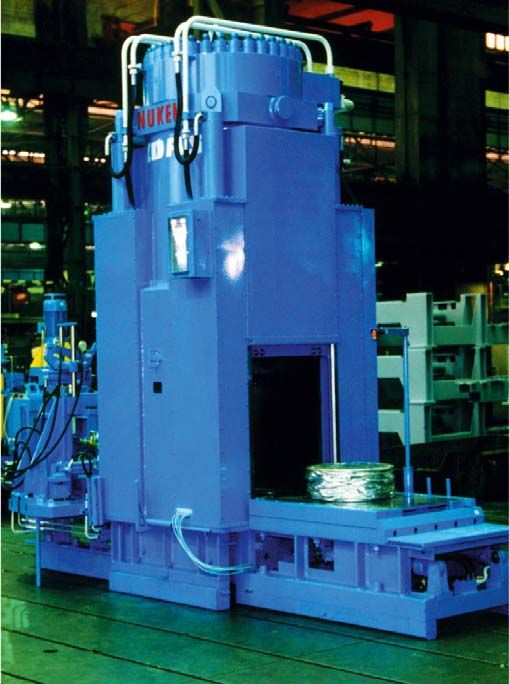
High Force Compactor: Technical Data
The figures below can be varied according to the waste streams

High force compactor body
Pressing force:                        variable, up to 20000 kN
Throughput:                            from 6 - 10 drums per hour
                                       (depending on the handling)
Bolster:                               1050 mm diameter
Main piston:                           matched with the drum diameter
Bolster liner:                         variable for different drum diameters
Material:                              ferrite steel

Dimensions
Height:                                approx. 4000 mm
Width:                                 approx. 1600/2100* mm      * with perforating
device
Length:                                approx. 4600 mm

Weights
Main compactor body                    250 kN
Drum infeed system (with drum)         max. 16 kN
Pellet delivery system (with pellet)   max. 16 kN
Hydraulic power pack (filled)          50 kN

6                                                           NUKEM Technologies GmbH
                                                                                2007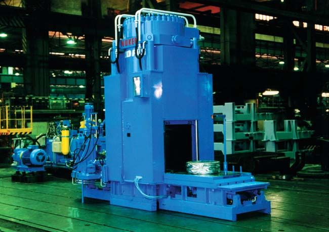
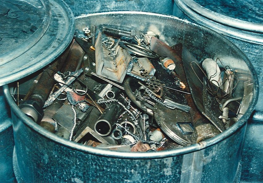
Fig. 2 High Force Compactor
Limits for materials to be compacted
Stress limit:                     Rp 0.2 = 400 N/mm² (e.g. pipe with a
                                  nominal diameter of DN 250, 15 mm thick)
Hardness limit:                   35 HRC
Drums
Diameter:                          max. 615 mm, min. 500 mm
Height:                            max. 900 mm
Weight:                            max. 12 kN
Control system
Type:                              Siemens S7 or similar
Hydraulic system
Operating pressures:               compacting: up to 50 MPa ,
                                   average 26 - 28 MPa
                                   filling: 10 MPa
Operating temperature:             30 - 50 °C
Auxiliaries
Power consumption:                 400 V, 50 Hz, 48 kW
Cooling water:                     approx. 0,070 m³/min at 5°C and 0.4 - 0.6
                                   MPa

NUKEM Technologies GmbH                                                        7
2007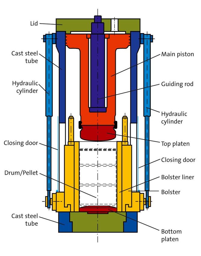
Fig. 3 Drummed mixed metal Scrap for compaction HFC 2000
Fig. 4 Drum with mixed metal scrap after compaction (1500 t)
8 NUKEM Technologies GmbH
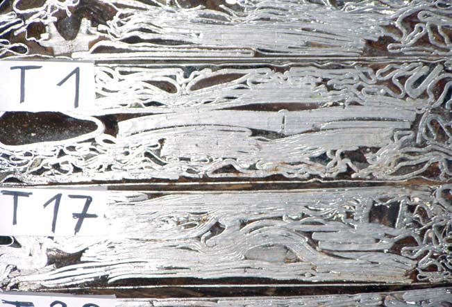
2007Fig. 5 Cross section cut: Drums with mixed metal scrap after compaction NUKEM Technologies GmbH 9 2007
The NUKEM In Drum Compactor Technology
The NUKEM In Drum Compactor                structure with an opening for
(IDC) unit consists of the following       inserting 200 litre drums. The upper
systems:                                   section forms the base for the
                                           compression plunger. Additionally, a
•    Main compactor body                   drum retainer can be lowered from
•    Drum protection sleeve
•    Feed gate
•    Plunger                               its upper position to hold the drum in
•    Switchgear for electrical     and     the correct position. After filling
     control equipment                     manually to a predetermined limit,
•    Control desk                          the compression plunger is lowered.
                                           Depending on the design, individual
Design and operation of the unit           maximum forces are achievable.
                                           One or two hydraulic cylinders are
                                           used to deliver the compaction force.
The design is highly flexible and can
                                           The maximum volume reduction ratio
be readily adapted to meet individual
                                           is a function of the waste
requirements.         The      following
                                           constituents and the applied force
description is given as an example to
                                           and can therefore vary over a wide
illustrate the overall concept.
                                           range.
Generally, In Drum Compaction
                                           In order to protect the surrounding
Technology          combines         the
                                           area from the spread of conta-
advantages of minimization the
                                           mination during this operation, a
number of drums required together
                                           drum protection sleeve is utilized.
with the ability to fill and document
                                           The displaced air or gas, together
the      contents     to   meet      the
                                           with particulates or aerosols, is
requirements of the regulations. The
                                           vented through the filling chamber.
system can be readily integrated into
                                           After retrieving of the plunger to its
a sorting system; indeed, NUKEM In
                                           upper position, additional waste can
Drum Compactors are usually
                                           be added. These steps can be
employed        within     such       an
                                           repeated as often as necessary to fill
environment.
                                           up the drum completely.
In this type of compactor, the main
compactor body is a welded steel

10                                                        NUKEM Technologies GmbH
                                                                              2007
IDC-160 and IDC-500 - Technical Data
Delivery part
Hydraulic unit and control panel: The IDC-160 / 500 is equipped with a
supply unit which consists of:
- Pumps
- Switches
- Level indicators
- Oil tank
- Control panel which is equipped with
operating and control devices, control
lights.
Connections
Hydraulic: all couplings which are mounted at the
compactor unit
Electric: The same as above, additional the
necessary cables
Hydraulic fluid: The first filling in the scope of supply
Ventilation: The system for IDC-160 has to be
connected to existing ventilation system
The system for IDC-500 consists of
blowers, pre-filter, absolute filter and
dumper
Functional: all functional steps are interlocked by limit
switches
Safety: all necessary safety devices and interlocks
are installed to protect the operating
personnel
NUKEM Technologies GmbH 11
2007Fig. 6 In Drum Compactor IDC-160
12 NUKEM Technologies GmbH
2007In Drum Compactor IDC-160: Technical Data
In Drum compactor body
Pressing force: variable, up to 160 kN
Main piston: matched with the drum diameter
Distance of piston movement: approx. 1200 mm
Pressing time: depending on the loading speed
Material: mild steel, painted with decontaminable
paint
Dimension
Height: approx.3700 mm
Width: approx.2300 mm
Length: approx.1300 mm
Weights
Total weight: approx. 40 kN
Material to be compacted
Paper, laundry waste, filter material, etc.
Drums
Volume: approx. 200 litre
Diameter: approx. 600 mm
Height: approx. 900 mm
Control system
Type: Siemens S7 or similar
Hydraulic system
Hydraulic fluid: fire resistant
Operating temperature: 30 - 50°C
Auxiliaries
Power consumption: 380 V / 50 Hz / power approx. 4 kW
Ventilation exhaust power: approx. 0.5 m³/min
NUKEM Technologies GmbH 13
2007In Drum Compactor IDC-500: Technical Data
In Drum compactor body
Pressing force: variable, up to 500 kN
Main piston: matched with the drum diameter
Distance of piston movement: approx. 1000 mm
Pressing time: depending on the loading speed
Material: mild steel, painted with decontaminable
paint
Dimension
Height: approx.3800 mm
Width: approx.1200 mm
Length: approx.1700 mm
Weights
Total weight approx. 55 kN
Material to be compacted
Metal, paper, laundry waste, wood, filter material, etc.
Drums
Volume: approx. 200 l
Diameter: approx. 600 mm
Height: approx. 900 mm
Control system
Type: Siemens S7 or similar
Hydraulic system
Hydraulic fluid: fire resistant
Operating temperature: 30 - 50°C
Auxiliaries
Power consumption: 380 V / 50 Hz / power approx. 7.5 kW
Ventilation exhaust power: approx. 7 m³/min
14 NUKEM Technologies GmbH
2007References
Scope of supply Client Putting in
operation
1 High Force Compactor Ignalina NPP (Lithuia) anticipated
(20000 kN) as part of the 2008
Ignalina Waste Treatment Centre
2 High Force Compactor Chernobyl NPP (Ukraine) anticipated
(20000 kN) as part of the ICSRM 2007
Project
3 High Force Compactor Leningrad NPP (Russia) anticipated
(20000 kN) as Part of the 2007
Leningrad NNP Waste
Treatment Centre
4 High Force Compactor Atomenergoexport / 2002
(20000 kN) as a part of the Balakovo NPP (Russia)
Balakovo NPP Waste Treatment
Centre
5 High Force Compactor China Institute of Atomic 2001
(20000 kN) for various solid Energy CIAE, Beijing (China)
waste
6 High Force Compactor SE a. s. / Bohunice NPP 2000
(20000 kN) as a part of the BSC- (Slovak Republic)
RAO Waste Treatment Centre
7 Design of High Force Compactor South-Ukraine NPP 1997
(20000 kN) as a part of the (Ukraine)
South-Ukraine NPP Waste
Treatment Centre
8 Design of High Force Compactor Chmelnitzki NPP (Ukraine) 1996
(20000 kN) as a part of the
Chmelnitzki NPP Waste
Treatment Centre
9 High Force Compactor (3000 kN) Kernforschungszentrum 1993
for Spent Fuel Scrap Karlsruhe GmbH (Germany)
10 Technical Support to design High BNFL (UK) 1992
Force Compactoer for PCM
Waste
11 Karlstein High Force Compaction Siemens (Germany) 1988
Unit (16000 kN)
NUKEM Technologies GmbH 15
200712 In Drum Compactor IDC–160 Uranium Enrichment Plant 1986
(160 kN) Gronau (Germany)
13 In Drum Compactor IDC–160 Uranium Enrichment Plant, 1985
(160 kN) Almelo (NL)
14 High Force Compaction Plant Kernforschungszentrum 1984
(16000 kN) Karlsruhe GmbH (Germany)
16 NUKEM Technologies GmbH
2007NUKEM Technologies GmbH
Industriestr. 13
63755 Alzenau
Germany
T +49 (0) 6023 9104
F +49 (0) 6023 911188
E info@nukem.de
NUKEM Technologies GmbH 17
2007Compaction of
Radioactive Waste
www.nukemgroup.comYou can also read