IMPORTANT CONSIDERATIONS WHEN SELECTING A FAN FOR FORCED AIR COOLING - By: Jeff Smoot
←
→
Page content transcription
If your browser does not render page correctly, please read the page content below
IMPORTANT CONSIDERATIONS
WHEN SELECTING A FAN FOR
FORCED AIR COOLING
By: Jeff Smoot
www.cuidevices.com

Important Considerations When
Selecting a Fan for Forced Air Cooling

                     Designing an appropriate thermal management solution requires a systemic
                     approach; each component on a circuit board will consume some power and, in
                     turn, contribute to the overall operating temperature. Most electronic components
                     are designed to work across a specific temperature range, but each one will have its
                     limits and its own unique thermal profile. Cooling technology comes in many forms,
                     but all make use of the fundamentals of conduction, convection and radiation for
                     removing unwanted heat. Understanding the thermal path for removing excess
                     heat in a system is the first step towards designing an efficient thermal solution.

                     In most systems, particularly those that employ an enclosure, some form of forced
                     air cooling will be required to optimize the basic cooling methods available and
                     to ultimately remove heat from the system. Invariably this will involve a fan of
                     some kind and there are now many options to choose from. Selecting the right fan
                     for the thermal management of an enclosed PCB is critical, as its efficiency and
                     effectiveness can have a significant impact on the overall lifespan of a system.

                     THE COOLING IMPERATIVE
                     The heat generated by passive components, integrated semiconductors and other solid
                     state devices is a by-product of their operation. Despite the efforts to produce ultra-low
                     power microcontrollers, the inescapable fact is that the movement of charge carriers
                     in a substrate generates heat. This points a finger at both the cause of the heat and the
                     necessity for effective heat management. Passive devices, predominantly power resistors,
                     have a maximum operating temperature, while most active devices, such as power
                     transistors, can tolerate a maximum junction temperature. In order to avoid cataclysmic
                     failure it is necessary to maintain an ambient temperature low enough to ensure the safe
                     operation of all components in a system.

                     Conduction of heat away from components throughout the PCB is the simplest means to
                     remove heat. However, when an electronic assembly is placed within an enclosure such as
                     a rack-mount, heat dissipation through conduction becomes less effective. For this reason,
                     assemblies that consume as little as 25 W of power may require forced-air cooling.

                     SYSTEM PROFILING
                     To design an appropriate cooling solution, it is imperative to create a thermal profile of the
                     system operating under all conditions in order to understand where and how much heat
                     is generated. This can be achieved by using temperature sensors distributed around a PCB
                     and within an enclosure, which provides the data necessary to move to the next stage,
                     defining the amount of cooling required.

Page   2
www.cuidevices.com
Important Considerations When
Selecting a Fan for Forced Air Cooling
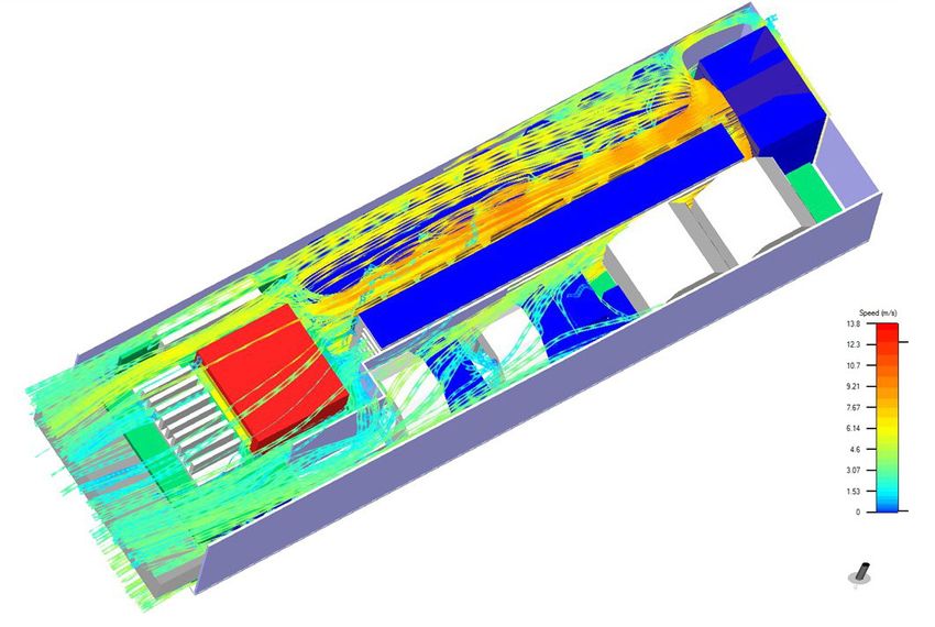
Figure 1:
An example of a
computational fluid
dynamics analysis
(CFD) which will
provide a very
accurate profile of
cooling requirements
Another important aspect of system profiling is determining the amount of impedance
to airflow a system exhibits. The system impedance, in terms of a drop in air pressure
between inlet and outlet, plays a major part in calculating the overall airflow required from
a fan and, in turn, the size and type of fan that should be designed in. Determining system
impedance can be achieved by measuring the pressure drop using sensors or, if possible,
by placing the system in an air chamber.
For larger systems, such as data centers, modeling the system using computational
fluid dynamics, or CFD, provides an even more accurate profile of a system’s cooling
requirements.
DETERMINING COOLING REQUIREMENTS
As described, effective thermal management of critical electronic components can be
achieved using appropriate levels of forced air cooling, but what is ‘appropriate’? To answer
this, it is necessary to examine and understand by how much the internal temperature can
change without increasing the risk of failure.
It is important to assess a design to determine the ‘most critical’ component in terms of
operating temperature; this will give a maximum ambient temperature. The cumulative
Page 3www.cuidevices.com
Important Considerations When
Selecting a Fan for Forced Air Cooling
power dissipation for all relevant components, such as power transistors, microprocessors,
amplifiers and communication interfaces, will provide a figure for the amount of power
dissipated by the overall design.
Power dissipated, in Watts, converts linearly to energy, in Joules/second, which is in
turn exhibited as heat. It can be assumed that the temperature of the air around the
components will continue to rise all the time the equipment is operating and at some point
will reach a level that will inhibit further heat from being removed. Replacing the heated
air with ambient air using forced air cooling is clearly the desired effect, which is why it is
crucial to specify a fan that can produce the appropriate level of airflow for the system.
Equation 1 shows the relationship between temperature rise and airflow, where q is the
amount of heat absorbed by the air (W), w is the mass flow of air (kg/s), Cp is the specific
heat of air ( J/kg • K) and ΔT is the temperature rise of the air (°C).
EQUATION 1: CALCULATING HEAT ABSORPTION
q = w x Cp x ∆T
Once the maximum permissible temperature within the enclosure is known and the
amount of heat generated is derived (based on the cumulative power/heat dissipated by
the components) it is possible to calculate the amount of airflow required. Since mass
flow (w) = air flow (Q) x density (ρ), substituting and solving for Q we can rewrite Equation
1 to get Equation 2 (where Q is the airflow in CMM (m3/min), q is the amount of heat to be
dissipated (W) and ρ is the density of air (kg/m3)).
EQUATION 2: CALCULATING THE AMOUNT OF AIRFLOW REQUIRED
Q = [q/(ρ x Cp x ∆T)] x 60
Substituting constants for Cp and ρ at 26°C, we can arrive at a general equation for
calculating airflow, as shown in Equation 3.
EQUATION 3: SIMPLIFIED EQUATION FOR CALCULATING AIRFLOW
Q = 0.05 x q/∆T; for Q in CMM
Q = 1.76 x q/∆T; for Q in CFM
The calculated airflow figure can now be compared against the specification for a fan. As
shown in Figure 2, manufacturers characterize fans using these two parameters, to provide
a performance graph that accurately plots airflow (measured in either Cubic Feet per
Minute, CFM, or Cubic Meters per Minute, CMM) against static pressure (measured in either
inches or millimeters of water, often written as Inch H2O or mm H2O).
Page 4www.cuidevices.com
Important Considerations When
Selecting a Fan for Forced Air Cooling
(Inch H2O)
(mm H2O)
Figure 2:
Typical performance
curve of an axial fan
0.50 14.00
12.00
0.40
STATIC PRESSURE
10.00
0.30
8.00
0.20 6.00
4.00
0.10
2.00
0.00 0.00
0.00 50.00 100.00 150.00 (CFM)
0.00 0.74 1.49 2.23 2.98 3.72 (CMM)
AIR FLOW
Figure 2 shows the performance curve of the CFM-120 Series from CUI Devices, a 120 mm
by 120 mm frame axial fan with dual ball bearing construction. Unfortunately, the result
given by Equation 3 is only accurate for ‘ideal’ conditions; with no back pressure from the
enclosure (known as System Impedance, as covered earlier). In reality there will always
be some system impedance, so in order to determine the real world requirements it is
paramount to calculate or estimate the system impedance. This can then be plotted on the
fan’s performance curve (Figure 3) and the point at which they cross should be taken as the
operating point for the fan.
As outlined earlier, measuring the airflow through an enclosure can be achieved using an
airflow chamber, but if that is not an option the alternative is to specify the operating point
above the figure derived from Equation 3. For example, if the airflow calculated is 50 CFM
with zero back pressure, over-specifying the fan such that it produces a maximum of 100
CFM with the intention of operating it at 75 CFM would provide a good margin of error, as
well as some headroom for increasing airflow during operation.
Page 5www.cuidevices.com
Important Considerations When
Selecting a Fan for Forced Air Cooling
(Inch H2O)
(mm H2O)
Figure 3:
The performance
curve of an axial
fan with System
Impedance plotted,
showing the 0.50 14.00
Operating Point
12.00
0.40
STATIC PRESSURE
10.00
0.30
8.00
System Impedance
Curve
0.20 6.00
4.00
0.10 Operating Point
2.00
0.00 0.00
0.00 50.00 100.00 150.00 (CFM)
0.00 0.74 1.49 2.23 2.98 3.72 (CMM)
AIR FLOW
Taking steps at the design stage to decrease or minimize system impedance can clearly
be beneficial in terms of specifying the size and power of a fan. At a minimum, it is
good practice to keep the areas around the air inlet and outlet as clear of components
as possible and to consider the additional system impedance a filter will introduce.
Component placement on the PCB should encourage airflow to and around critical
components, using guides if needed.
In addition, it should be appreciated that the above equations also use air density at sea
level. If a system is expected to be used at altitudes significantly above sea level it is crucial
that this is taken into account. Air density reduces with altitude, so a significant increase
in altitude would result in a correspondingly significant increase in airflow required to
maintain the same level of cooling.
Page 6www.cuidevices.com
Important Considerations When
Selecting a Fan for Forced Air Cooling
CHOOSING THE RIGHT FAN DESIGN
As well as being available in both ac and dc configurations, fans are generally categorized
by the way the air enters and leaves the fan; if it exits in the same plane as it enters it is
normally termed an axial fan, as to draw air in from one side and expel it from the other. If
the airflow leaves in a different plane it is normally referred to as a centrifugal design, as the
air drawn in changes direction inside the fan and is expelled in a different direction. This
style of fan can effectively compress the air, allowing it to deliver a constant airflow under
different pressures. Perhaps the most prolific centrifugal fan design is the blower, which
resembles an axial fan but typically expels air at 90° to the intake.
The volume of airflow needed and the static pressure of the system will influence the most
appropriate style of fan for a given application. Axial fans are predominantly suitable for
high airflow in systems with low static pressure, while centrifugal fans offer lower airflow,
but can deliver it against higher static pressure.
Both audible and electrical noise are also important considerations when selecting a fan.
While the advantages of using a dc fan have been touted above, often these benefits are in
direct competition with the audible noise generated by their operation. The general rule
of thumb being the greater the airflow required, the greater the audible noise. Thus, axial
fans will typically have lower audible noise than a blower. Careful design to optimize airflow
and reduce system impedance, thus reducing the required CFM, are critical in order to
minimize the audible noise generated.
In addition to audible noise, dc fans can have other unwanted system effects. The dc
motor within the fan does create an electromagnetic interference (EMI) signature. EMI
generated by the fan is normally limited to conducted EMI in the power leads. This can
generally be effectively suppressed with ferrite beads, shielding or filtering. For most PCB
based systems in an enclosure, the dc axial fan provides the right balance between cost,
audible noise, electrical noise (EMI) and performance.
There are differences in the construction of axial fans that may also be relevant depending
on the application. Specifically these differences relate to the bearings, which are either
steel ball bearings or sintered powdered bearings, usually referred to as sleeve bearings.
At consistently low temperatures, sleeve bearings can operate as well as ball bearing fans,
however at variable or high temperatures ball bearings have been shown to operate longer
and more reliably. Sleeve bearing fans, which are normally cheaper than ball bearing fans,
do have their place, but their relatively shorter lifetime and propensity to failure at high
temperatures limits their overall suitability.
As an alternative to sleeve or ball bearings, CUI Devices has developed the omniCOOL™
system, an advanced sleeve bearing design that bridges the cost-performance gap
Page 7www.cuidevices.com
Important Considerations When
Selecting a Fan for Forced Air Cooling
between traditional bearings on the market. This technology incorporates a magnetic
structure that enables rotor-balancing to minimize tilt, wobble, and friction, allowing
for operation at any angle. It also integrates either a specially hardened bearing or a
specialized groove bearing that both work to extend operational life, while decreasing fan
noise and friction due to a reduced need for lubricant. In addition, the omniCOOL system’s
simple design makes it easier to manufacture, more reliable, and more cost-effective than
more complex designs.
ACTIVE CONTROL AND VARIABILITY
Axial fans are widely used in rack-mount enclosures thanks to their combination of small
size, low power and high airflow. Many also include additional features that can further
improve system performance by providing greater control over the speed of operation,
thereby optimizing a design for overall power consumption. As described, calculating the
minimum airflow rate required to cool a PCB housed within an enclosure allows for the
specification of a fan that can deliver adequate cooling under all conditions. This assumes
that the fan will run constantly, even when maximum cooling is not required. While this
is not likely to result in failure, it does assume worst-case conditions at all times and is
therefore inefficient from a system point of view and will also reduce the operating lifetime
of the fan.
Because of this it has become common practice to monitor the temperature within an
enclosure and only turn a fan on when it is required. While this approach can improve the
lifespan of the fan and reduce audible noise, it can present problems in terms of thermal
lag. It can also introduce a fault condition if for some reason the fan is unable to start due
to an obstruction in the fan.
To address this, modern dc axial fans like those from CUI Devices include auto-restart
protection as a standard feature. This feature detects when the fan motor is prevented from
rotating and automatically cuts the drive current.
VoH
VoL
Figure 4: T1 T2 T3 T4
Diagram to illustrate
how the signal T
supports speed
detection One Rotation
T1-4 = (1/4)T
N = Fan Rotational Speed (min-1)
Page 8www.cuidevices.com
Important Considerations When
Selecting a Fan for Forced Air Cooling
PULL UP VOLTAGE
PULL UP RESISTOR
Figure 5: +
Diagram to illustrate DC FAN
output signal
sensor SENSOR OUTPUT
indicating stall/lock
fault lc = 10 mA max
-
Models including the CFM-60V Series also offer optional controls such as tachometer and
rotation detection sensors. The tachometer detects the rotational speed of the fan motor
and provides a pulsed output that can be used within control circuitry (see Figure 4). If
the motor stops, the output stops pulsing and stays at either a logic high or logic low. The
rotation detection feature doubles as a lock sensor; if the fan motor stops, the output is
driven to a logic high and remains at a logic low during normal operation (Figure 5).
In addition, there is the ability to control the speed of the fan using Pulse Width Modulation
(PWM); the duty cycle of this input determines the speed of the fan’s rotation, the
relationship between the duty cycle and whether the fan’s speed is linear. When used in
conjunction with a simple algorithm running on a microcontroller it is possible to create
a sophisticated thermal management solution that can adapt to system conditions and
provide more efficient operation.
A simple example of implementing fan control could consist of a single or multiple
temperature sensors distributed around a board. Many modern ICs now include
temperature sensors, which can be used for this purpose. Using zones provides greater
visibility into the system, particularly for components most susceptible to heat variations.
As soon as the measured temperature approaches a predetermined level, the fan can
be turned on or speed can be increased by changing the duty cycle of the PWM signal
to provide the necessary cooling (see Figure 6). Correspondingly, the fan’s speed can be
reduced if the internal temperature is below an acceptable level.
Figure 6: T = T1 + T2 ,α = T1/T Vs
Changing the
Va
fan speed can α = Duty-Cycle
be achieved by
changing the duty Va =α x Vs
cycle of the PWM T
signal Vs = 4~5 V T1 T2
T
Page 9www.cuidevices.com
Important Considerations When
Selecting a Fan for Forced Air Cooling
CONCLUSION
Forced air cooling is an efficient way of implementing effective thermal management
for an enclosed PCB and choosing the correct fan for the application is vital. With
semiconductors and PCBs becoming ever more complex and dense, if a component fails,
statistically it will be because it overheated or operated for too long at a critical junction
temperature. If the level of forced air cooling is insufficient for the system’s needs, the
fan will most definitely be the main cause of failure, even though that failure will typically
manifest itself as some other critical component failing. With so much to risk, selection
of the right fan should not be approached casually and can be the difference between a
premature failure and an efficiently operating system.
View CUI Devices’ full line of dc fans and blowers
LEARN MORE
Page 10 © 2021 CUI Devices. All rights reserved. 06/2021You can also read