Basic Operations-Main Screen Set-up, Set-up Menus, Machine Settings, CNC Tool Data, Delivery Protocols, Warranties, Packaging/RMA Procedures ...
←
→
Page content transcription
If your browser does not render page correctly, please read the page content below
Smartshop SUV Manual 2021
Basic Operations-Main Screen Set-up, Set-up Menus, Machine Settings,
CNC Tool Data, Delivery Protocols, Warranties, Packaging/RMA
Procedures.

Laguna Tools
744 Refuge Way
Grand Prairie, TX. 75050
Direct Phone #: (800) 234-1976
Warranty Repair Information: (800) 332-4094                  1
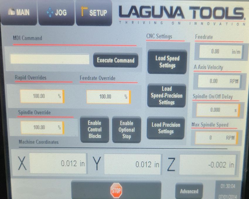
Table of Contents-
•   Main Screen Buttons & Flow.
•   CNC Positions.
•   Machine Settings.
•   Edit/Check “G” Code.
•   CNC Tools Data.
•   Axis Calibration.
•   Program Manager.
•   CNC Settings.
•   Axis Settings.
•   “Jog” Positions.
•   “Settings” from Main Screen.
•   Program Preview from Main Screen.
•   Alarm Screens.
•   Schematics.
•   Delivery Protocol.
•   Parts & Service.
•   Warranty.
•   Packaging/RMA Procedures/Bill of Lading.   2
Main Screen Button(s) & Flow-

                                “Main” Screen

                                                3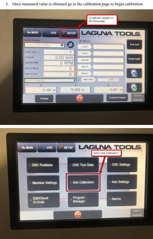
Main / Home Screen Defined-

                                   Above is the Start-Up Home Screen-
Park Tool = Pressing this button will put the active tool in spindle into its tool holder and leave the spindle
empty.
Preventive Maintenance Note-
*****One should never leave a tool in spindle when machine is Idle. Leaving a tool in spindle will
cause rust and damage to tool holder and or spindle.

Verify Origin = Pressing this button will move the machine to whatever ZPO (Z-Point Origin) Coordinates
is selected on the Jog screen, G54-G59.                                                                           4
****ZPO (Z-Point Origin) coordinates – These are based on the G54-G59 set and selected from the Jog Screen.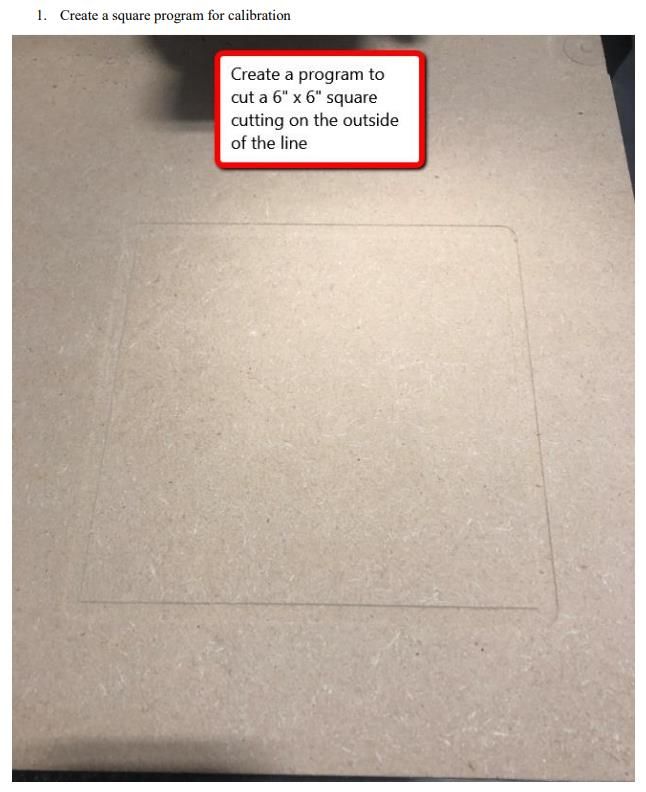
Main / Home Screen Defined-

                                                                             Hold

                                                                             Run

             Settings                                              Preview Program

Hold = The Hold button is used to Pause a program run. Press the Run button to continue.
NOTE: The spindle stays running during hold. Press stop button to stop the spindle and program.
Run = The Run button is used to start a CNC Program.
Preview Program = This button will open a visual representation of the active program in X and Y axis
and provide a estimated run time.
Settings = The settings button enters the Override / MDI screen. This is also accessible from the set-up
                                                                                                  5
menu screen under CNC Settings.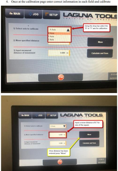
Main / Home Screen Defined (Cont’d.)-
Right Side Fields defined:

 Select Program drop down window = This field
 allows you to quickly select a program from the
 files copied to the controller’s memory.

 Active Tool = This references the current tool in
 spindle.

 Feed rate = This shows the current federate as
 dictated by the active program.

 Spindle RPM = This shows the current spindle speed.

 Start at Block = This is the run from line number
 function. With the machine in a Stopped state input
 the line in which you would like to start from and
 press the Run button.

 Start at Tool = This field allows the program to jump
 to a specific tool for it’s starting point. Input the tool
 number desired then press run. There will be a slight
 delay while the code is scanned to the requested
 starting point.

                                                              6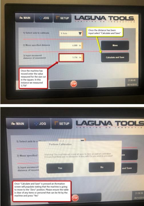
Main / Home Screen Defined (Cont’d.)-

                                                     CNC Monitor = These 5 lines are
                                                     displaying the CNC “G”-Code as
                                                     it is running.

 Coord’s Selector/Lower Right Drop
 Down = This is the selector for the X,Y,
 and Z coordinates displayed at the
 bottom of the Main Page.

 FROM DRP DOWN MENU-
 1. ZPO Coordinates – These are based
    on the G54-G59 set and selected from
    the Jog screen.

 2. Machine Coordinates – These are the
    actual distances from machine “Zero”.

 3. Relative Coordinates – These are
    resettable to zero from current         DROP DOWN MENU
    position and equate to a digital tape
    measure function.

                                                                                       7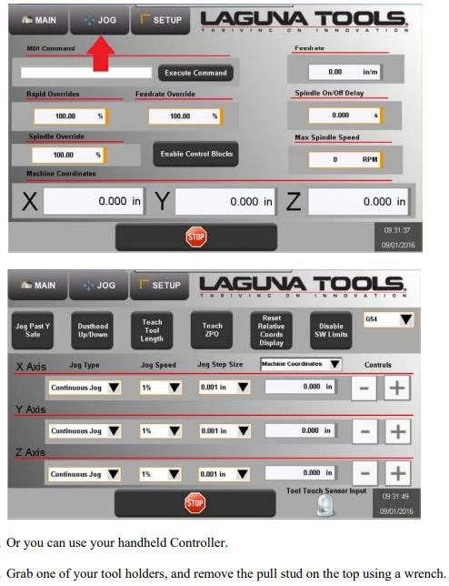
Main Screen Buttons & Flow to proceed to CNC Positions-
1. Make sure one is in “Machine Coordinates”.

2. From the “Main Screen” select the “SET UP” Button, then it will proceed to
                                                                                “Set-Up” Screen Appears-
“Set-Up” Screen.

                                                                                                           8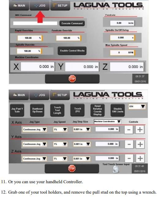
CNC Positions-
 2a. Select “CNC Positions” Button.

                                      4a.Press “Main” Button to return to amin/Home Screen.

                                                                                              9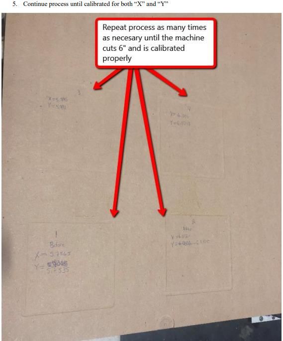
CNC Positions (Cont’d.)-

                           6. Then press the “Settings” Button.

                                                                  10
CNC Positions (Cont’d.)-
11CNC Positions (Cont’d.)-
10. Press “Jog” Button to return to manual page to allow for manual jogging of the
machine.
12CNC Positions (Cont’d.)-
13CNC Positions (Cont’d.)-
14CNC Positions (Cont’d.)-
15CNC Positions (Cont’d.)-
20. Press “CNC Positions”.
16CNC Positions (Cont’d.)-
17Machine Settings- This screen is to manage the machine settings. These settings consist of the Calibration, Tool Changer Locations, and Machines Limits. Pressing the “Save to CF Button” will write a copy of the machine settings to the controller’s memory. Pressing “Save Settings to USB” is recommended so a hard copy of machine settings is available if service requires them to reinitialize the system. This is also very handy for or service people so your machine can be exactly replicated in our shop for troubleshooting. 18
Machine Settings (Cont’d.)-

    “Import Settings from USB”
    = This is used for recovery
    purposes if the controller
    was to be replaced.
    “Units Field” = This is used
    to toggle the machine
    between Standard and
    Metric Units of Measure

    “Password Field” = This is used to access the much deeper settings that only a Laguna
    technician would need to access. Servo tuning and motion settings can be done on the
    controller. This eliminates the need for a technician to be on site for tuning issues if they arise.
                                                                                                     19
Machine Settings (Cont’d.)-
Pressing “Save Settings to USB”
is recommended so a hard copy
of machine settings is available
if service requires them to
reinitialize the system. This is
also very handy for or service
people so your machine can be
exactly replicated in our shop
for troubleshooting.
20“G-Code” Edit & Check-
“Check Code” = This button will a program
test by pre-running the code. This will check
that the code can be run within the machine
limits and “ZPO”= “Zero Point Origin”.
“Code Editing” = Use the arrow
keys and associated buttons to
perform quick code edits on the
machine.
21From “Set-Up” Screen to CNC Tool Data-
“Tools Screen”: This page is used for all data regarding Tooling Dimensions and Offsets.
“Tool Selection Drop Down Field” = Use
this to select the tool in which you wish to
manipulate. The tool number displayed
propagates the fields below with its
current data and allows for full manual
adjustments if needed.
“Tool Length Field” = This represents the
distance from Z home to the end of the
cutter. This can be propagated by the
automatic touch off routine, manually set
with data entry or taught By “Teach Tool
Button” followed by “Set Tool Data
Button”.
“Manual Setting of Tool Length” = Use the Jog
function to move the cutter to the table or “Execute Automatic Touch Off (TTO)” = Select the tool in which needs to
work surface. Press the “Teach Tool Length be measured and press The “Execute Button”. The machine will gather the
correct tool holder and proceed to the TTO switch. “Z” will rapid to the
Button” to measure the Z Axis Distance. Press
“Z” pre-dimension in the machine settings then slow until it finds the
“Set Tool Data” to write the measurement to switch.
the machine settings. Failure to press the “Set 22
Tool Data” will lose the measured value.CNC Tool Data (Cont’d.)-
“Tools Screen”: This page is used for all data regarding Tooling Dimensions and Offsets.
“Tool Selection Drop Down Field” = Use
this to select the tool in which you wish to
manipulate. The tool number displayed
propagates the fields below with its
current data and allows for full manual
adjustments if needed.
“Tool Length Field” = This represents
the distance from “Z” home to the
end of the cutter. This can be
propagated by the automatic touch
off routine, manually set with data
entry or taught By “Teach Tool
Button” followed by “Set Tool Data
Button”.
23From “Set-Up” Screen to CNC Tool Data (Cont’d.)-
“Tools Screen”: This page is used for all data regarding Tooling Dimensions and Offsets.
“Execute Automatic Touch Off (TTO)” = “Manual Setting of Tool length” =
Select the tool in which needs to be Use the Jog function to move the
measured and press “The Execute cutter to the table or work surface.
Button”. The machine will gather the Press the “Teach Tool Length Button”
correct tool holder and proceed to the to measure the Z axis distance.
TTO switch. Press “Set Tool Data” to write the
“Z” will rapid to the “Z” pre-dimension measurement to the machine
in the machine settings then slow until settings. Failure to press the “Set
it finds the switch. Tool Data” will lose the measured
value.
“Set Tool in Spindle” = This
field allows for the manual
adjustment of the active tool
physically in the spindle. If you
manually swap tool cones
around you must update the
machine so the active tool is
properly represented.
“Tool Touch Sensor Input” = This is an
indicator to verify the Tool Touch Off (TTO)
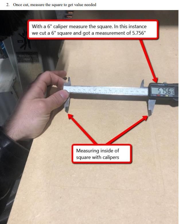
switch is working properly. 24“Axis Calibration” Procedure-
25“Axis Calibration” Procedure-
26“Axis Calibration” Settings-
27“Axis Calibration” Settings-
28“Axis Calibration” Settings-
4.) Cont’d.
29“Axis Calibration” Settings-
30From “Set-Up” Screen to Program Manager-
“USER TAB” – TO THE CUSTOMER:
DO NOT UTILIZE OR USE IN ANY
WAY.
“Programs Tab” – This displays the
programs within a specified folder.
“USB Tab” – This displays the
programs from a USB stick when
inserted into the control
cabinet. “Copying Programs to the Controller” = A
program must be selectable from the
Programs Tab in order to be made active.
31“Program Manager”-
“Refresh Button” = This buttons polls the program
storage area and brings the list up to a real time
reference.
“Multiselect Button” = This
button allows the selection
of multiple programs for
pasting into another
location or deleting.
d.) Press the “Paste
Button” to insert the
“G-Code” into the
Use the “USB Tab” to select program folder for
from a flash drive. active selection.
c.) Highlight a program and press the
“Copy Button”. Then open the
Programs tab and select an empty
field.
The following buttons are standard file manager functions just like those used in P.C.’s.
Rename, Create directory, Copy, Cut, Paste, and Delete do exacting what they say.
32From “Set-Up” Screen to Program Manager-
“Refresh Button” = This buttons polls the program
storage area and brings the list up to a real time
reference.
“Multiselect Button” = This
button allows the selection
of multiple programs for
pasting into another
location or deleting.
d.) Press the “Paste
Button” to insert the
“G-Code” into the
b.) Use the “USB Tab” to program folder for
select from a flash drive. active selection.
c.) Highlight a program and press the
“Copy Button”. Then open the
Programs tab and select an empty
field.
The following buttons are standard file manager functions just like those used in P.C.’s.
Rename, Create directory, Copy, Cut, Paste, and Delete do exacting what they say.
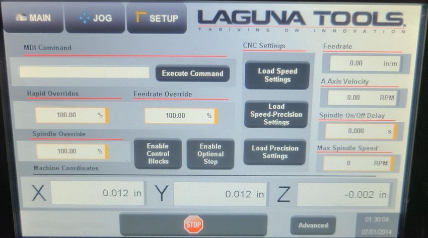
33“CNC Settings”/Override Screen Defined-
Enter the “CNC Settings” page from the
Settings button in the lower left of the Main
Screen or from the “CNC Set Up Button” on
the Set-Up Menu Screen.
“Overrides” = This screen allows for the
adjustment of the “Rapid Feed Rate”,
“Cutting Feed Rate” and the
“Spindle RPM”. You can adjust all three
with a percentage above or below the
set parameters while the program is
running.
34“CNC Settings” (Cont’d.)-
CNC Settings-
“MDI Field” = Manual Data Input is
“Load Speed Settings” = ?
for executing a single line of code
“Load Speed Precision Settings”=?
at a time or a “M Code”. Simply
“Load Precision Settings”=?
input the desired function and
press “Execute Command” to
activate.
Feed Rates-
“Feed Rate Field” = This field displays the
programmed feed rate in the “G” Code.
“A Axis Velocity” =This Field displays?
“Spindle On/Off Delay” = This is used to force an
On and Off delay in the control of the spindle.
This is in lieu of a programmed delay or used as
an additional delay to the programmed ramp up
and down.
“Max Spindle Speed” = This field must match
the maximum speed you speed can rotate. This
is only used if your factory spindle is replaced
with a different top speed.
35“CNC Settings (Cont’d.)-
“Enable Control Blocks” = This is function for higher end users “Enable Optional Stop” = This
that want to use “Control Blocks” such as shown below: Button enables a M0 to cause a
program pause for additional
operations or jigging during a
program run. Pressing Run
Button on the Main screen
restarts the program from the
pause. With this Button off the
“M0” is ignored.
“Advanced” = This can only be accessed by
use of a password and is used by
technicians to perform Servo tuning
adjustments. There are no user functions
“DRO Display” (Digital here.
Readout Display) = The “Stop” = This button cancels the program
Digital Read Out’s at the currently running.
bottom of this screen
reference the current
machine coordinates for
X, Y, and Z.
36“Axis Settings” Position-Setting “Absolute Zero”- “Home Zero Button”
1. Bring all Axis as close to the “Zero” position as possible.
2. Press “Re-Home Button” on Screen when homing in to “Absolute Zero (0) on the X, Y, &
Z Axis of the Machine.
37“Axis Settings” Positions-Setting “Absolute Zero” in case no “ReHome Button” available.
1. Bring all Axis as close to the “Zero” position as possible
2. Turn off machine and manually move the machine so that the end of the linear rails are
3” away from the bearing cards on each Axis.
3. “Y” Axis ABS (ABS=Absolute).
38“Axis Settings” Positions-Setting “Absolute Zero” (Cont’d.)
4. “X” Axis ABS (ABS=Absolute).
39“Axis Settings” Positions-Setting “Absolute Zero ” (Cont’d.)
5. “Z” axis ABS (ABS=Absolute).
40“Axis Settings” Positions-Setting “Absolute Zero ” (Cont’d.)
6. Navigate to the Axis Settings page (Setup → Axis Settings).
7. Verify that the “X”, “Y”, and “Z” axis are all 3” from end of the rail to the bearing card and
the Press “Re-Home”.
Press “Re-Home”
Button.
41Alarm Screens-
This screen will display the “3 Types of Alarms” that can be generated in the
controller. The “Check Marks” is used to acknowledge and clear a single alarm
at a time to see all that occurred.
The “Next Button” will open the Axis Specific Alarms page.
42Main Screen Buttons & Flow- Main Screen to “Jog” Screen
“Main” Screen
“Jog” Screen
43Jog Screen Defined-
1. Jog Past “Y” Safe = This button is used for
maintenance and repair issues only. There is
no operator function for this.
2. Dust Hood Up/Down = This button is used to
manually retract or extend the dust hood.
3. Teach Tool Length = This button is used to
manually set tool length for the active tool.
This is handy on the jog page, so you don’t
have to toggle to the tools page while
manually jogging to a Z reference.
4. Teach Zero Point ZPO = This button will write
the current X and Y locations to the Zero
Point Offset selected from the “Upper Right
Field G54- G59”.
5. Reset Relative Coord’s Display = This button
resets the Relative position of X and Y to
Zero. Use would be a digital tape measure.
6. Disable Switch Limits = This button is used
for maintenance and repair issues only. There
is no operator function for this.
44Jog Screen Defined (Cont’d.)-
“Jogging Functions”= There are 3 settings for
Jogging. ipm=Inches Per Minute
DROP DOWN MENU for the X Axis, Y Axis, & Z Axis-
1st – Select the Jog type, Either Continuous Jog or a
Step jog at a specified increment.
2nd – For continuous Jog, select the percentage of
the max speed set in the controller. If max speed is
1000 ipm, then 50% Jog speed will move the Axis at
500 ipm.
3rd – For step jog select the step size you wish to
Tool Touch Sensor Input = This is an
increment jog at for each push of the jog + or –
indicator to verify the Tool Touch Off
button. Use the + and or – button to move the Axis
(TTO) switch is working properly.
Forward or Back.
45Main Screen Buttons & Flow-
“Main” Screen
“Program Preview Screen”
46“Settings” Button from Main Menu/ Override Screen Defined-
47“Settings” from Main Menu / Override Screen Defined (Cont’d.)-
“MDI Field” = Manual Data
Input is for executing a single
line of code at a time or a “M
Code”. Simply input the desired
function and press “Execute
Command” to activate.
“Feed Rate Field” = This field
displays the programmed feed rate
in the “G” Code.
“Spindle On/Off Delay” = This is
used to force an On and Off delay in
“Max Spindle Speed” = This field must match the
the control of the spindle. This is in
maximum speed you speed can rotate. This is only
lieu of a programmed delay or used used if your factory spindle is replaced with a
as an additional delay to the different top speed.
programmed ramp up and down.
48Main Menu “Settings” / Override Screen Defined (Cont’d.)-
“Enable Control Blocks” = This is function for higher end
users that want to use “Control Blocks” such as shown “DRO Display” (Digital
below: Readout Display) = The
Digital Read Out’s at
the bottom of this
screen reference the
current machine
coordinates for X,Y, and
Z.
“Stop” = This
button cancels the
program currently
running.
“Overrides” = This screen allows for the
adjustment of the “Rapid Feed Rate”,
“Cutting Feed Rate” and the
“Spindle RPM”. You can adjust all three
with a percentage above or below the
set parameters while the program is
running. 49Program Manager-
“Program Preview Screen”: This screen will pre-run the selected “G-Code” and
give a X and Y Graphical Representation of the Program as shown below.
50Program Manager-
“USER TAB” – TO THE CUSTOMER
DO NOT UTLIZE OR USE IN ANY
WAY.
“Programs Tab” – This displays the
programs within a specified folder.
“USB Tab” – This displays the
programs from a USB stick when
inserted into the control
cabinet. “Copying Programs to the Controller” = A
program must be selectable from the
Programs Tab in order to be made active.
51Program Manager-
“Refresh Button” = This buttons polls the program
storage area and brings the list up to a real time
reference.
“Multiselect Button” = This
button allows the selection of
multiple programs for pasting
into another location or
deleting.
d.) Press the “Paste
Button” to insert the
“G-Code” into the
b.) Use the “USB Tab” to program folder for
select from a flash drive. active selection.
c.) Highlight a program and press the
“Copy Button”. Then open the
Programs tab and select an empty
field.
The following buttons are standard file manager functions just like those used in P.C.’s.
Rename, Create directory, Copy, Cut, Paste, and Delete do exacting what they say.
52Set-Up / Networking Screen-
The information contained in this screen is used
for networking directly to the controller. This is
needed for file transfers and remote diagnostic
functions Via a P.C. Network.
See Chapter on making a “Network Connection”.
53Alarm Screens-
The “Alarms” displayed on this screen are Axis Specific.
54Schematics-
55Schematics-
56Schematics-
57Schematics-
58Schematics-
59Schematics-
60Schematics-
61Schematics-
62Schematics-
63Schematics-
64Schematics-
65Schematics-
66Schematics-
67Schematics-
68Delivery Protocol-
• Most large machinery will be delivering on a tractor trailer 48'-53' long. Please notify Sales Representative with any Delivery
Restrictions.
• Customer is required to have a forklift (6000lb. or larger is recommended) with 72" forks or fork extensions and operator.
• Note any visible damage, torn packaging, scuffs or any abnormal marks on the delivery receipt or Bill of Lading (BOL).
69Parts & Service
70Laguna Tools Warranty-
Dealer Machinery Warranty
New woodworking machines sold by Laguna Tools carry a two-year warranty effective from the date of dealer invoice
to customer/end-user. Machines sold through dealers must be registered with Laguna Tools within 30 days of
purchase to be covered by this warranty. Laguna Tools guarantees all new machine sold to be free of manufacturers’
defective workmanship, parts and materials. We will repair or replace, without charge, any parts determined by
Laguna Tools, Inc. to be a manufacturer’s defect. We require that the defective item/part be returned to Laguna Tools
with the complaint. The end-user must request an RMA (return material authorization) number from Customer
Service and include the (RMA) number with any and all returned parts/components requesting warranty coverage.*
Any machines returned to Laguna Tools must be returned with packaging in the same manner in which it was
received. If a part or blade is being returned it must have adequate packaging to ensure no damage is received during
shipping. In the event the item/part is determined to be damaged due to lack of maintenance, cleaning or
misuse/abuse, the customer will be responsible for the cost to replace the item/part, plus all related shipping
charges. This limited warranty does not apply to natural disasters, acts of terrorism, normal wear and tear, product
failure due to lack of maintenance or cleaning, damage caused by accident, neglect, lack of or inadequate dust
collection, misuse/abuse or damage caused where repair or alterations have been made or attempted by others.
**NOTE: Issuing an RMA number is for referencing materials and issues, it does NOT indicate warranty
acceptance/conformity.Laguna Tools Warranty-
CNC Limited Warranty
New CNC machines sold by Laguna Tools carry a one-year warranty effective from the date of shipping. Laguna Tools guarantees all new
machine sold to be free of manufacturers’ defective workmanship, parts, and materials. We will repair or replace without charge, any
parts determined by Laguna Tools, Inc. to be a manufacturer’s defect. We require that the defective item/part is determined to be
damaged due to lack of maintenance, cleaning or misuse/abuse, the customer will be responsible for the cost to replace the item/part,
plus all related shipping charges. This limited warranty does not apply to natural disasters, acts of terrorism, normal wear and tear,
product failure due to lack of maintenance or cleaning, damage caused by accident, neglect, lack of or inadequate dust collection,
misuse/abuse or damage caused where repair or alterations have been made or attempted by others.
Laguna Tools, Inc. is not responsible for additional tools or modifications sold or performed (other than from/by Laguna Tools, Inc.) on any
Laguna Tools, Inc. woodworking machine. Warranty maybe voided upon the addition of such described tools and/or modifications,
determined on a case-by-case basis. Software purchased through Laguna Tools, Inc., is not covered under this warranty and all technical
support must be managed through the software provider. Normal user alignment, adjustment, tuning and machine settings are not
covered by this warranty. It is the responsibility of the user to understand basic woodworking machinery settings and procedures and to
properly maintain the equipment in accordance with the standards provided by the manufacturer.
Parts under warranty are shipped at Laguna Tools, Inc.’s cost either by common carrier, FEDEX ground service or a similar method.
Technical support to install replacement parts is primarily provided by phone, fax, e-mail or Laguna Tools Customer Support Website. The
labor required to install replacement parts is the responsibility of the user. Laguna Tools is not responsible for damage or loss caused by a
freight company or other circumstances not in our control. All claims for loss or damaged goods must be notified to Laguna Tools within
twenty-four hours of delivery.
****Please contact our Customer Service Department for more information. Only NEW machines sold to the original owner are covered
by this warranty. For warranty repair information, call 1-800-332-4094. Copyright 2013 Laguna Tools, Inc. **Warning – no portion of
these materials may be reproduced without written approval from Laguna Tools, Inc.Laguna Tools Warranty-
Laguna Tools Warranty-

                             No Modifications Allowed or Sold.
Laguna Tools, Inc. is not responsible for additional tools or modifications sold or performed (other
than from/by Laguna Tools, Inc.) on any Laguna Tools, Inc. woodworking machine. Warranty
maybe voided upon the addition of such described tools and/or modifications, determined on a
case-by-case basis. Normal user alignment, adjustment, tuning and machine settings are not
covered by this warranty. It is the responsibility of the user to understand basic woodworking
machinery settings and procedures and to properly maintain the equipment in accordance with
the standards provided by the manufacturer. Parts, under warranty, are shipped at Laguna Tools,
Inc.’s cost either by common carrier, FEDEX ground service or a similar method. Technical support
to install replacement parts is primarily provided by phone, fax, e-mail or Laguna Tools Customer
Support Website. The labor required to install replacement parts is the responsibility of the user.
Laguna Tools is not responsible for damage or loss caused by a freight company or other
circumstances not in our control. All claims for loss or damaged goods must be notified to Laguna
Tools within twenty-four hours of delivery. Please contact our Customer Service Department for
more information. Only new machines sold to the original owner are covered by this warranty.
For warranty repair information, call 1-800-332-4094.
Laguna Tools Packaging/RMA Procedures- Dealer Machinery Warranty **Any machines returned to Laguna Tools must be returned with packaging in the same manner in which it was received. If a part or blade is being returned it must have adequate packaging to ensure no damage is received during shipping. In the event the item/part is determined to be damaged due to lack of maintenance, cleaning or misuse/abuse, the customer will be responsible for the cost to replace the item/part, plus all related shipping charges. We require that the defective item/part be returned to Laguna Tools with the complaint. The end-user must request an RMA (Return Material Authorization) Number from Customer Service and include the (RMA) number with any and all returned parts/components requesting warranty coverage.
Laguna Tools Packaging/Laguna Tools RMA Example-

              RMA #
Laguna Tools Packaging/Laguna Tools BILL of LADING Example-
77You can also read