How To Model
Grassed Waterways
  Using Eagle Point
←
→
Page content transcription
If your browser does not render page correctly, please read the page content below
How To Model Grassed Waterways Using Eagle Point

Grassed Waterways

Table of Contents

Table of Contents ..............................................................................................................................i
Introduction ...................................................................................................................................... 1
Setting Up an Eagle Point Project ................................................................................................... 2
Importing Survey Data..................................................................................................................... 4
Creating a Surface Model................................................................................................................ 6
Adding a RoadCalc Sub-project .................................................................................................... 10
Defining an Alignment ................................................................................................................... 11
Extracting Original Ground Cross-sections ................................................................................... 13
Defining a Design Profile ............................................................................................................... 16
Creating Channel Shapes ............................................................................................................. 18
Processing the Design................................................................................................................... 22
Reports .......................................................................................................................................... 24
Graphics ........................................................................................................................................ 28
Index .............................................................................................................................................. 30

                                                                                                                                                     i
Introduction

   The following document explains how to model grassed waterways using Eagle Point. The
   process takes you through the steps of starting an Eagle Point project, importing survey
   data, making a surface model, defining a waterway alignment, obtaining existing ground
   cross-sections, defining a proposed grade profile, developing the channel shape, and
   creating reports and graphics.

   Commands in the Data Collection, Surface Modeling and RoadCalc modules are used
   throughout the process. In particular, the Define Channel command (rcdefinechannel)
   found in RoadCalc is used to create the design channel of the waterway.

   Hydraulic and soil conditions need to be calculated through USDA-NRCS approved
   applications such as the Ohio Engineering Programs or custom spreadsheets. The Define
   Channel command is then used to create a parabolic or trapezoidal channel shape and
   define the design conditions and locations. Once the design is processed, you are able to
   use the Offset/Depth report under the Step Through or Query Cross-section Data
   commands to query the depth of the channel surface measured from the original ground.
Setting Up an Eagle Point Project

   You will start by creating a new Eagle Point project.

   1.   Open Eagle Point by double clicking on the Eagle Point AutoCAD or Eagle Point
        Standalone icon on the desktop.
   2.   Click on the New icon in the Open dialog box or select File Æ New from the Eagle
        Point menu.

   3.   Highlight Eagle Point Project and click Next.

   4.   Type a Project Description.
   5.   Select a Project Drawing.

   Note: If you do not have an existing drawing, Eagle Point will create it for you. In this case,
   you will need to select or create a directory where to store the project files and create a file
   name.

   6.   Select the Prototype Settings.
   7.   Click Finish when you are ready to continue.
   8.   In the Open dialog box, select the newly created project.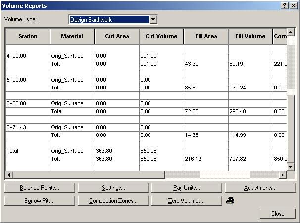
9. Click OK to open the project.
10. From the Eagle Point menu, select Tools Æ Plot Scales.

Note: All annotation and symbol sizing within Eagle Point is based on these plot scales. It is
recommended to verify and/or change the project plot scales.

11. Enter the desired Horizontal and Vertical plot scales and click OK to accept changes.
Importing Survey Data

   We will assume that electronic methods were used to collect all project data. This allows for
   all survey data to be imported and processed electronically. We will now use Data
   Collection to import and reduce the survey.

   1.   From the Eagle Point menu, select Products Æ Data Collection.

   2.   Select Jobs Æ Download from Collector.
   3.   Type in a job name, select a format, select a COM port, and set the transfer rate and
        parity to match your data collector.

   4.   Click OK and follow the instructions on the screens to transfer the data from your
        collector to the computer. Steps may differ depending on the type of data collector.
   5.   Select Jobs Æ Reduce.

   Note: To verify the reduction settings for the default field code or the linework table to be
   used, click on Settings. The survey file can be previewed before committing the data to the
   drawing. To do this, click on Preview.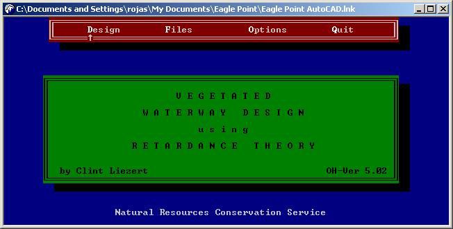
6.   Select the Job Name and click OK to reduce the file to the drawing.
Note: If you previewed the job, click on the Place button in the Preview window. If
necessary, review and correct the errors or problems listed under the Query Warnings
dialog box. To make corrections to the survey data, you may use the Edit Formatted File
command found in the Jobs menu.
7.   Close Data Collection.
Note: Other methods of importing or plotting survey data through Eagle Point include the
use of the Data Transfer or COGO modules.

Creating a Surface Model

   Surface models (TIN) are the result of the triangulation of the points and breaklines in the
   drawing that represent existing or proposed conditions. Surface Modeling will triangulate
   to all the points, lines, arcs, polylines,and blocks in the drawing. To prevent Surface
   Modeling from triangulating to undesired objects, these can be masked or the layers that
   contain them can be frozen in the CAD layer manager.

   1.   From the Eagle Point menu, select Products Æ Surface Modeling.

   2.   Select Prepare Æ Manage Surface Models and click on the New button.
   3.   In the New Surface Model dialog box, select the Surface Model tab.
   4.   Type in a Description for the surface.
   Note: Elevation ranges can also be adjusted to filter out invalid data.
   5.   Click on the Contours tab.
   6.   Adjust the contour Intermediate Interval and Index Interval as necessary.
   7.   Adjust the Smoothing Factor. A smoothing factor of 3 to 5 will render good “smooth-
        looking” contours without increasing the drawing file size too much.
   8.   Set the construction method to LW Polylines to reduce the drawing file size.

   9. Click on OK to accept all the changes in the New Surface Model dialog box.
   10. Click Close on the Manage Surface Models dialog box.
   Note: To further restrict the information to be used during the triangulation process, you can
   draw a closed polyline to serve as a boundary. This boundary polyline can be drawn as a
   2D or 3D line and can be selected during triangulation or predefined to save some time if
   you will triangulate a surface multiple times.

   In case of internal features where you want to prevent the software from triangulating, such
   as buildings, lagoons or others, you may draw closed polylines to be used as void regions.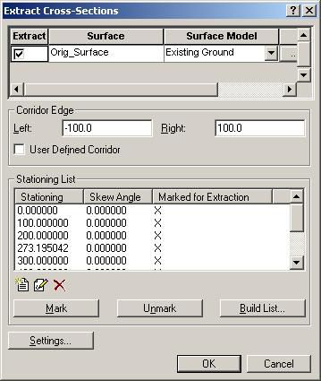
These polylines can also be drawn as 2D or 3D polylines and can be selected during
triangulation or predefined to save some time if you will triangulate a surface multiple times.

If any lines that define significant features (breaklines) were drawn, it will be necessary to
check for conflicting intersections. By finding and fixing any crossing breaklines, Surface
Modeling is able to resolve elevation conflicts and have the TIN diagonals better match the
linework. If the crossing breaklines are not fixed, Surface Modeling will not apply those
specific lines to the triangulation.

11. Select Prepare Æ Crossing Breaklines.
12. From the Action list, select Find.
13. Click Apply.

14. If any crossing breaklines were found, use the Show and/or Mark All options found
    under the Action list to review the linework.
15. The Repair options under the Action list can be used to resolve the conflicts. Select
    the Crossing # to repair, then select the Repair Method from the list and click on
    Apply.

Note: Crossing breaklines can also be fixed using CAD commands.

16. Click on Close.

Now you are ready to triangulate the surface model.

17. From the Surface Modeling menu, select Triangulate Æ Surface Model.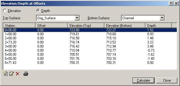
Note: If a boundary and/or void regions were drawn, select the appropriate option – Select
or Predefined – under the Boundary and Void Regions pull-downs.
18. Toggle Display Model. Surface Modeling displays the triangulation using temporary
    objects. The objects will disappear as soon as the drawing is redrawn by use of the
    zoom, pan, redraw, or regen CAD commands.
Note: To place permanent triangles, toggle on Place Triangles.
19. Click Apply to perform the triangulation.
20. Select the objects you want included in the triangulation.
Note: Any CAD selection method can be used, e.g., Window, Last, Crossing, ALL, Fence,
Wpolygon, Cpolygon, etc.
21. Accept the selection group by pressing Enter.
Note: Depending on the boundary and void region choices, you may be prompted to select
the boundary and void regions.
22. Once the triangulation is done, you are returned to the Triangulate Surface Model
    dialog box. Click Close.

With a surface model created, you can now place the contour lines.

23. From the Surface Modeling menu, select Contours Æ Make Intermediate and Index.

24. Click Apply.
25. Once the contour lines are placed, you are returned to the Make Intermediate and
    Index Contours dialog box. Click Close.
26. You can now close Surface Modeling. Note: You can annotate the contour lines by selecting Contours Æ Annotate. You can also annotate the elevation of any point in the surface model by selecting Output Æ Place Spot Elevation Labels.
Adding a RoadCalc Sub-project

   Now that you have defined a surface model, you need to add a RoadCalc sub-project to
   develop the alignment, existing ground cross-sections, original/proposed profiles, and
   channel sections for the waterway. The centerline alignment defined in a RoadCalc sub-
   project is the geometry that the program uses to base the cross-sections and profiles from.

   1.   From the main Eagle Point menu, select File Æ New.
   2.   Highlight RoadCalc Sub-project and click Next.

   3.   In the RoadCalc Sub-project dialog box, your current Eagle Point project is selected in
        the Project List and a proposed Sub-project Number is displayed.
   4.   Type a Description. Then click Next.

   Note: If you have a project with multiple waterways, you may need to define a sub-project
   for each one of them, e.g., each controlling alignment must have its own sub-project.

   5.   In the New Sub-project dialog box, accept the Use Project Drawing selection by
        clicking Finish.
   6.   In the Open dialog box, the newly created RoadCalc sub-project should be highlighted.
        Click OK to open it.
Defining an Alignment
Alignments represent the two-dimensional horizontal geometry of a given baseline. The
centerline alignment being the geometry from which RoadCalc bases the cross-sections
and profiles.
Alignments can be created numerically or graphically in the plan view graphic. Alignment
vertex (PI) and curve data can be entered in the alignment data dialog boxes using nodes,
coordinates, or angles and distances. Or, you may use CAD tools to draw lines or arcs for
the alignment directly into the plan graphic. The steps that will be followed in this document
are based on the assumption that the alignment will be entered graphically.
1. You may want to freeze some layers in CAD to have an easier view of the site.
2. In CAD, draw a 2D polyline representing what you will use as the waterway centerline.
Note: If you have proposed centerline shots, you can snap the polyline to them. All
distances and angles can be later modified through the Edit Data dialog box found under
Alignments Æ Edit Data.
3. In RoadCalc, select Alignments Æ Convert Objects to Alignment.
4. You are prompted to select the object or objects in CAD. Select the object(s).
Note: Any CAD selection method can be used, e.g., Window, Last, Crossing, ALL, Fence,
Wpolygon, Cpolygon, etc.
5. Press Enter to accept the selection.
6. You are prompted to ‘Pick a point near the beginning of the alignment’. Select a point
close to the end where you want the stationing to begin.
7. In the Convert Objects to Alignment dialog box, make sure that Centerline is the
selected Alignment.
8. Input a Beginning Station if it is other than 0+00.
Note: If you have a known station point along the centerline, click on Station Data and then
Reference Station to pick that point. RoadCalc adjusts the project stationing accordingly.
9. Click Apply.
Note: As the selected polyline gets converted into a RoadCalc alignment, it changes layer
and color to match the CAD settings – red by default.
10. To verify the alignment, select Alignments Æ Edit Data.To round up station, distance, and/or angular values for the waterway centerline, click on the Modify PI button and make the necessary adjustments. 11. Click on Close once you are done reviewing the alignment data. Note: To avoid cross-section overlaps or “blind spots” you can add a 1-foot radius curve to the alignment vertices (PI). This prevents sharp angles from occurring.
Extracting Original Ground Cross-sections

   The commands found in the Cross-Sections menu allow you to input, edit, and translate
   the cross-sectional data. Enter and edit the data directly with the edit cross-sections routine,
   or bring the cross-section data into RoadCalc from outside sources using the extract cross-
   sections or the import cross-sections routines.

   You will take advantage of the fact that a surface model was created earlier using Surface
   Modeling.

   1.   In RoadCalc, select Cross-Sections Æ Extract Cross-Sections.
   2.   The Build Station List dialog box displays.

   3.   By default, RoadCalc proposes that cross-sections be extracted for the entire project.
        You can accept the default Station Range or adjust it.
   4.   Input the Stationing Interval at which you want to obtain cross-section data.
   5.   Leave Curve Stations toggled for RoadCalc to extract cross-section at the vertices of
        the alignment.
   6.   Make sure that Mark Stations For Extraction is toggled on.
   7.   Click OK.
   8.   The Extract Cross-Sections dialog box displays.
9. Toggle on the surface for which you will Extract data.
10. Select the Surface Model to be used.
11. If needed, modify the extent to which data will be extracted by entering new values for
the Corridor Edge.
12. All stations should be Marked for Extraction in the Stationing List.
13. Click OK to extract the cross-sections. As a result, RoadCalc draws “shadow” lines at
each cross-section station.
14. To review the cross-sections in RoadCalc, select Cross-Sections Æ Edit Cross-
Section Data.
Note: You can select the desired station from the Station list. The Shot at Station list
reports the offset, elevation, slope, etc., data for each shot.15. To preview the cross-sections, click on the Query Cross-Section button on the lower
left hand corner of the Edit Cross-Section Data dialog box.
The left and right arrows move the cursor along the selected surface to obtain offset,
elevation, and slope data. The (+) and (-) buttons move through the stations. The list
button allows you to select a given station. The scale view button adjusts the displaying
settings.
16. Click Close to close the Query Cross-Section dialog box.
17. Click Close to close the Edit Cross-Section Data dialog box.Defining a Design Profile
The commands in the Profiles menu define profiles and specify other design constraints
that RoadCalc uses to generate design cross-sections. RoadCalc uses the centerline
design profile to determine at what elevation to place the typical sections on the original
cross-sections.
The profile data can be entered graphically or numerically. RoadCalc automatically
supplies you with an original ground centerline profile based on cross-sections, so you may
sketch a design profile using CAD and then convert those objects into a profile that can be
modified using the Edit Profile Data command. If you know the station, elevations, and
curve data, that information may be entered using the Edit Profile Data dialog boxes.
For the purpose of this document, we will assume that the profile data will be entered
graphically.
1. In RoadCalc, select Profiles Æ View Profile Graphics. RoadCalc creates the original
ground profile in a new CAD drawing by default.
2. In CAD, draw a 2D polyline that represents the proposed profile (grade line) of the
waterway centerline.
Note: Grades and distances can be modified using the Edit Data dialog box.
3. In RoadCalc, select Profiles Æ Convert Objects to Profile.
4. In CAD, you are prompted to “select objects”. Select the polyline that was drawn in the
previous step and accept the selection set.
5. Click on Next on the Convert Objects to Profile dialog box.
6. Select Centerline and click on Finish.
Note: The line changes layer and color as it is converted into a RoadCalc design profile.
7. To verify and/or adjust the profile in RoadCalc, select Profiles Æ Edit Data.8. To adjust the proposed profile station – depth and/or the distance – grade you can
modify the profile vertices (VPI). Select the desired vertex and click on the Modify VPI
button.
9. Click on Close once you are done adjusting or reviewing the profile.
10. In CAD, save the drawing.
Note: If you need to report the original ground profile, you can add a new design profile
named “Original Ground” through Profiles Æ Manage. Then you can convert the profile
that RoadCalc automatically created into the “Original Ground” profile or you can extract a
profile from the surface model into the “Original Ground.” With the profile created, you can
now use the Generate Reports command found in the Profiles menu.Creating Channel Shapes
The Define Channel command was added to RoadCalc. The key-in command of
"rcdefinechannel" displays the Define Channel dialog box. This command was designed
for the NRCS and other conservation engineering organizations to aid in the design of
grassed waterways.
The Define Channel command allows you to launch an external program to determine the
shape for the channel. It also automatically builds parabolic and trapezoidal channel shapes
according to the widths, depths, and side slopes specified. Once the channel shapes have
been constructed, they can be assigned to profile grade change (vertex/VPI) locations. With
the channel shapes specified at the profile grade change locations, a default condition is
built and the channel shape and conditions are automatically entered to the design
locations so you are ready to process the design.
1. To develop the channel typical section, you need at least one design surface. In
RoadCalc, select Cross-Sections Æ Manage Surfaces. Then click on the Design
tab.
2. Click on the New Surface button.
3. Type the new surface Name in the New Design Surface dialog box. For example, type
Channel as the design surface name.
4. Click OK.
5. Click Close.
6. At the CAD command prompt, type rcdefinechannel and press Enter.7. The Define Channel dialog box displays.
By default, the Define Channel dialog box shows the beginning elevation and grade for
each reach. The first time you open the command, no Channel Sections are selected.
Once sections have been defined and assigned they are appropriately displayed.
8. To configure the application to be used to calculate the waterway design shape, click
on Calculator Settings.
By default, RoadCalc searches for the Vegetated Waterway Design executable
(GWW.EXE) from the USDA-NRCS Ohio Engineering program suit. If this executable is
not installed in the default program path, you need to adjust the default path. To use a
different USDA-NRCS program, spreadsheet, or other program, click on the appropriate
toggle for Executable, Spreadsheet, or Other. Then click on the Browse icon to the right
of the field to browse and select the application to be used for this project’s calculations.
9. Click OK to accept the settings.
10. Click on Calculate Shape. This opens the application picked for the calculations.For example:
The Define Channel command supports both parabolic and trapezoidal channel
shapes. Compute the width and depth of the desired waterway design shape for each
reach using your NRCS application.
11. Once done with the calculations, close the application to return to Eagle Point.
12. Click on New Channel Shape.
13. Select the desired Shape from the list.
14. For Parabolic shapes, type in the calculated Width and Depth. A default Name and
Extended Description are proposed. The and entries in the Name field are
replaced automatically with the values entered once the OK or Apply button is clicked.
15. For Trapezoidal shapes, type in the calculated Bottom Width, Depth, and Side
Slope. A default Name and Extended Description are proposed. The and
entries in the Name field are replaced automatically with the values entered once the
OK or Apply button is clicked.
Note: If you need to enter more than one shape, click Apply to accept each entry and keep
the dialog box open. If you are entering only one shape definition or are at the last entry,
click OK to accept the entry and close the New Channel Shape dialog box.
16. Click the Channel Section list and select the desired shape for each waterway reach.17. Click OK to close the Define Channel dialog box. Define Channel creates and assigns a default Condition Table to the sub-project. The Condition Table is based on the cut and fill slopes defined in the selected RoadCalc Sub- project prototype and is assigned to all the stations in the waterway. Note: If you need to adjust the profile data, click on Edit Profile. The Define Channel dialog box allows you to access the application you usually use to calculate the waterway shape design. Note: You can predefine some of the waterway design settings, including the program or spreadsheet used to calculate the waterway design shape, by creating a RoadCalc Sub- project Prototype that includes that information.
Processing the Design

   The Run Design command is used to "pull" the individual design elements together to
   produce design cross-sections. You may choose to have RoadCalc automatically process
   all stations in the processed range and then view the designed cross-sections in the Edit
   Cross-sections Data dialog box. Or you may choose to "step through" all of the processed
   cross-sections one at a time, or "step through" the cross-sections that produce warning
   messages during processing. Either "step through" method displays the cross-sections in a
   window for quick viewing and editing.

   1.   In RoadCalc, select Process Æ Run Design. You may enter the station range over
        which you want to process the design.

   2.   To view the designed cross-sections as they are processed, select Step Through All
        from the Method list.
   Note: If no “step through” method is selected, cross-sections can be reviewed through the
   Edit Cross-Section Data Æ Query Cross-section command once RoadCalc has finished
   processing the design.
   3.   Click on Run to process the cross-sections.
   4.   The Step Through Cross-Sections dialog box displays.
The channel Offset and Depth can be reported at various breakpoints in the cross-
section. Select the Channel surface from the Surface list. Then click on the left or right
arrows to displace the cursor along the surface. The offset and depth values are reported
in the respective fields in the dialog box.
5. Click the View Previous or View Next cross-section buttons to display different
stations.
6. Click Close to finish.Reports
RoadCalc provides multiple output features, including alignment and profile reports,
elevation and depth reports, cross-section staking, volumes, and plot sheets (cross-section
and plan and profile sheets). Alignment and profile reports are available through the
Alignments and Profiles menus while the Output menu provides access to various other
commands.
While the printout format is controlled by the Print Setup command, plotting will be done
and configured in CAD. You can specify if you want the printout to be sent to a printer or
file, if you want page headers, command headers, how many lines are printed per page,
width to the left margin, and how many columns are printed.
1. From the Eagle Point menu, select File Æ Print Setup. Select Printer or File. You can
also modify the header settings.
2. Click OK to accept changes and close the dialog box.
You will now report the waterway centerline and the design profile.
3. From the RoadCalc menu, select Alignments Æ Generate Reports.
4. Toggle on P.I. Data.
5. Click Print. RoadCalc reports the waterway centerline information.
6. From the RoadCalc menu, select Profiles Æ Generate Reports.7. Toggle on VPI Data. 8. Click Print. RoadCalc reports the waterway proposed profile information. Follow the next steps to report the cut values at the centerline of waterway. 9. From the RoadCalc menu, select Output Æ Elevation/Depth at Offsets. 10. Toggle on Depth. 11. Select your original surface as the Top Surface. 12. Select Channel as your Bottom Surface. 13. Click on the New Offset button. 14. Type 0 and then click OK. Note: By using a zero offset, you will obtain the centerline profile cut values. 15. Click Calculate. 16. Click on the Print Elevation/Depth at Offsets icon. 17. Click Close. Follow the next steps to report the cut values at the edges of the waterway. 18. From the RoadCalc menu, select Output Æ Cross-Section Staking.
19. Click Calculate.
Note: To view all data, use the scroll bar to display the remaining data.
20. Click on the Cross-Section Staking Print Options icon.
21. Select which items to include in the printout by toggling on or off the Print field.
Note: The Width field controls the number of characters that will fit on the respective fields.
22. Click on Print.
23. Click Cancel to close the Cross-Section Staking dialog box.

To report the volume (earthwork) calculations, proceed with the following steps.

24. From the RoadCalc menu, select Output Æ Volumes.
25.   Click on the Print Volume Report icon.
26.   Select Raw Volumes.
27.   Click on Print.
28.   Click Close.
Graphics

   You will now create the plot sheets – cross-section and plan and profile sheets – for the
   waterway project. For each type of sheet created, numerous parameters controlling sizes,
   CAD settings, and other text annotation may be set and saved to prototypes that can be
   used in other RoadCalc sub-projects.

   To obtain cross-section sheets, follow these steps:

   1. From the RoadCalc menu, select Output Æ Cross-Section Sheets. To adjust the
      sheet or CAD settings or any other annotation, select an item from the Format list and
      then click Edit.

   2. Click on the New Cross-Section Sheets icon. You can adjust the station range.

   3. Click OK.
   Note: To review any specific sheet, select the sheet number and then click on the View
   Cross-section Sheets icon.
   4. Click Close.

   To obtain plan and profile sheets, follow these steps:
1. From the RoadCalc menu, select Output Æ Plan and Profile Sheets. To adjust the
sheet or CAD settings or any other annotation, select an item from the Format list and
then click Edit.
2. Click the New Plan and Profile Sheets icon. You can adjust the station range.
3. Click OK.
Note: To review any specific sheet, select the sheet number and then click on the View
Plan and Profile Sheet button icon.
For more information related to the use of Data Collection, Surface Modeling, RoadCalc or any
other Eagle Point programs, refer to the on-line help, documentation, tutorials, or call the Eagle
Point support line.Index
New · 2
A
N
Alignments · 11
Convert Objects to Alignment · 11 New Surface Model · 6
Edit Data · 11
P
B
Plan and Profile Sheets · 29
Boundary · 6 Print Setup · 24
Breaklines · 7 Profiles · 16
Convert Objects to Profile · 16
Edit Data · 16
C View Profile Graphics · 16
Contours · 8
Crossing Breaklines · 7 R
Cross-Section Sheets · 28
Cross-sections · 13 Reduce · 4
Build Station List · 13 Report
Edit Cross-Section Data · 14 Alignments · 24
Query Cross-Section · 15 Cross-Section Staking · 25
Cross-sections Elevation/Depth · 25
Extract Cross-sections · 13 Profiles · 24
Cross-Sections Volumes · 26
New Design Surface · 18 RoadCalc Sub-project · 10
Run Design · 22
D
S
Data Collection · 4
Define Channel · 18 Surface Modeling · 6
Calculate Shape · 19
Calculator Settings · 19
Channel Section · 20 T
Dialog box · 19
Edit Profile · 21 Triangulate · 7
New Channel Shape · 20
Parabolic Shape · 20
V
rcdefinechannel · 18
Trapezoidal · 20
Void regions · 6
Download from Collector · 4
E
Eagle Point Project · 2Premium VIP Support: 888.637.6507
Toll-free 800.678.6565
Fax 563.556.5321
4131 Westmark Drive
Dubuque, IA 52002-2627
--------------------------------------------
www.eaglepoint.comYou can also read