HPLCHPLC - Pump 40P Instructions
←
→
Page content transcription
If your browser does not render page correctly, please read the page content below

Pump 40P
Instructions

HPLC
               Document no. V7613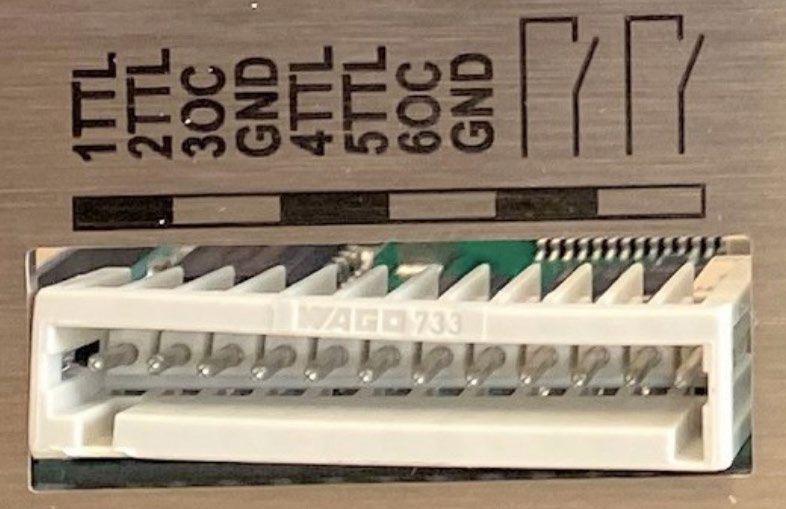
Note: For your own safety, read the instructions and observe the war-
                        nings and safety information on the device and in the instructions.
                        Keep the instructions for future reference.

                        Note: In case you require this instruction in another language, please
                        submit your request including the corresponding document number via
                        e-mail or fax to KNAUER.

           Support:     Do you have questions about the installation or the operation of your
                        instrument or software?
                        International Support:
                        Contact your local KNAUER partner for support:
                        www.knauer.net/en/Support/Distributors-worldwide

                        Support in Germany
                        (Austria & Switzerland on case-to-case basis):
                        Phone: +49 30 809727-111 (workdays 9-17h CET)
                        Fax :    +49 30 8015010
                        Email:     support@knauer.net

          Publisher:    KNAUER Wissenschaftliche Geräte GmbH
                        Hegauer Weg 38
                        14163 Berlin
                        Germany
                        Phone:		        +49 30 809727-0
                        Fax:		          +49 30 8015010
                        Internet:       www.knauer.net
                        E-Mail:		       info@knauer.net

Version information:    Document number: V7613
                        Version number: 1.1
                        Release date: 2021/04/14
                        Translation of the original edition
                        The information in this document is subject to change
                        without prior notice. For the latest version of the instructions,
                        visit our website: www.knauer.net/library.

      Sustainability:   The printed versions of our instructions are printed according to Blue
                        Angel standards (www.blauer-engel.de/en/uz195).

         Copyright:     This document contains confidential information and may not be
                        reproduced without written consent of KNAUER Wissenschaftliche
                        Geräte GmbH.

                        © KNAUER Wissenschaftliche Geräte GmbH 2021
                        All rights reserved.
Table of Contents
1.   General . . . . . . . . . . . . . . . . . . . . . . . . . . . . . . . . . . . . . . . . . . . . . . . . . . . . . . . . . . . . . . . . . . . . . . . . . . . . . .  1

      1.1         About these instructions. . . . . . . . . . . . . . . . . . . . . . . . . . . . . . . . . . . . . . . . . . . . . . . . . . . . . . . . .  1
      1.2         Signal words. . . . . . . . . . . . . . . . . . . . . . . . . . . . . . . . . . . . . . . . . . . . . . . . . . . . . . . . . . . . . . . . . . .  1
      1.3         Additional typographical conventions. . . . . . . . . . . . . . . . . . . . . . . . . . . . . . . . . . . . . . . . . . . . .  1
      1.4         Legal information. . . . . . . . . . . . . . . . . . . . . . . . . . . . . . . . . . . . . . . . . . . . . . . . . . . . . . . . . . . . . . .  2
                     1.4.1         Liability limitation. . . . . . . . . . . . . . . . . . . . . . . . . . . . . . . . . . . . . . . . . . . . . . . . . . . . . .  2
                     1.4.2         Transport damage. . . . . . . . . . . . . . . . . . . . . . . . . . . . . . . . . . . . . . . . . . . . . . . . . . . . .  2
                     1.4.3         Warranty conditions . . . . . . . . . . . . . . . . . . . . . . . . . . . . . . . . . . . . . . . . . . . . . . . . . . .  2
                     1.4.4         Warranty seal . . . . . . . . . . . . . . . . . . . . . . . . . . . . . . . . . . . . . . . . . . . . . . . . . . . . . . . . .  2
                     1.4.5         Declaration of conformity. . . . . . . . . . . . . . . . . . . . . . . . . . . . . . . . . . . . . . . . . . . . . . .  2

2.   Basic safety instructions. . . . . . . . . . . . . . . . . . . . . . . . . . . . . . . . . . . . . . . . . . . . . . . . . . . . . . . . . . . . . . . .  3

      2.1         Intended use. . . . . . . . . . . . . . . . . . . . . . . . . . . . . . . . . . . . . . . . . . . . . . . . . . . . . . . . . . . . . . . . . . .  3
                     2.1.1         Operating ranges . . . . . . . . . . . . . . . . . . . . . . . . . . . . . . . . . . . . . . . . . . . . . . . . . . . . .  3
                     2.1.2         Foreseeable misuse. . . . . . . . . . . . . . . . . . . . . . . . . . . . . . . . . . . . . . . . . . . . . . . . . . . .  3
      2.2         User qualification. . . . . . . . . . . . . . . . . . . . . . . . . . . . . . . . . . . . . . . . . . . . . . . . . . . . . . . . . . . . . . .  3
      2.3         Operator responsibility. . . . . . . . . . . . . . . . . . . . . . . . . . . . . . . . . . . . . . . . . . . . . . . . . . . . . . . . . .  4
      2.4         Personal safety equipment. . . . . . . . . . . . . . . . . . . . . . . . . . . . . . . . . . . . . . . . . . . . . . . . . . . . . . .  4
      2.5         Working with solvents. . . . . . . . . . . . . . . . . . . . . . . . . . . . . . . . . . . . . . . . . . . . . . . . . . . . . . . . . . .  5
                     2.5.1         General requirements. . . . . . . . . . . . . . . . . . . . . . . . . . . . . . . . . . . . . . . . . . . . . . . . . .  5
                     2.5.2         Contamination by health-threatening solvents. . . . . . . . . . . . . . . . . . . . . . . . . . . . .  5
                     2.5.3         Avoiding leakage. . . . . . . . . . . . . . . . . . . . . . . . . . . . . . . . . . . . . . . . . . . . . . . . . . . . . .  5
      2.6         Specific environments. . . . . . . . . . . . . . . . . . . . . . . . . . . . . . . . . . . . . . . . . . . . . . . . . . . . . . . . . . .  6
                     2.6.1         Earthquake-endangered areas. . . . . . . . . . . . . . . . . . . . . . . . . . . . . . . . . . . . . . . . . .  6
                     2.6.2         Explosive environment. . . . . . . . . . . . . . . . . . . . . . . . . . . . . . . . . . . . . . . . . . . . . . . . .  6
                     2.6.3         Cooling room. . . . . . . . . . . . . . . . . . . . . . . . . . . . . . . . . . . . . . . . . . . . . . . . . . . . . . . . .  6
                     2.6.4         Wet room . . . . . . . . . . . . . . . . . . . . . . . . . . . . . . . . . . . . . . . . . . . . . . . . . . . . . . . . . . . .  6
      2.7         Maintenance, care and repair . . . . . . . . . . . . . . . . . . . . . . . . . . . . . . . . . . . . . . . . . . . . . . . . . . . .  6
      2.8         Service request form and decontamination report . . . . . . . . . . . . . . . . . . . . . . . . . . . . . . . . . .  7

3.   Product information . . . . . . . . . . . . . . . . . . . . . . . . . . . . . . . . . . . . . . . . . . . . . . . . . . . . . . . . . . . . . . . . . . .  8

      3.1         Views . . . . . . . . . . . . . . . . . . . . . . . . . . . . . . . . . . . . . . . . . . . . . . . . . . . . . . . . . . . . . . . . . . . . . . . . .  8
                     3.1.1         Front view. . . . . . . . . . . . . . . . . . . . . . . . . . . . . . . . . . . . . . . . . . . . . . . . . . . . . . . . . . . .  8
                     3.1.2         Rear view. . . . . . . . . . . . . . . . . . . . . . . . . . . . . . . . . . . . . . . . . . . . . . . . . . . . . . . . . . . . .  8
      3.2         Features. . . . . . . . . . . . . . . . . . . . . . . . . . . . . . . . . . . . . . . . . . . . . . . . . . . . . . . . . . . . . . . . . . . . . . .  9
      3.3         Pump heads . . . . . . . . . . . . . . . . . . . . . . . . . . . . . . . . . . . . . . . . . . . . . . . . . . . . . . . . . . . . . . . . . . .  9
      3.4         RFID recognition . . . . . . . . . . . . . . . . . . . . . . . . . . . . . . . . . . . . . . . . . . . . . . . . . . . . . . . . . . . . . . .  9
      3.5         Symbols and signs. . . . . . . . . . . . . . . . . . . . . . . . . . . . . . . . . . . . . . . . . . . . . . . . . . . . . . . . . . . . . 10

                                                     BlueShadow Pump 40P Instructions V7613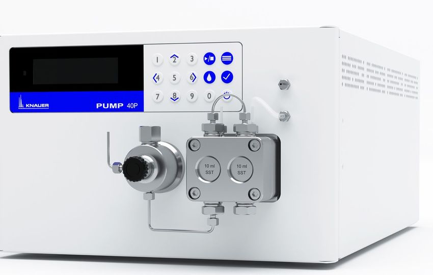
Table of contents

      3.6         Scope of delivery. . . . . . . . . . . . . . . . . . . . . . . . . . . . . . . . . . . . . . . . . . . . . . . . . . . . . . . . . . . . . . 10

4.   Installation and initial startup . . . . . . . . . . . . . . . . . . . . . . . . . . . . . . . . . . . . . . . . . . . . . . . . . . . . . . . . . . 11

      4.1         Unpacking. . . . . . . . . . . . . . . . . . . . . . . . . . . . . . . . . . . . . . . . . . . . . . . . . . . . . . . . . . . . . . . . . . . . 11
      4.2         Ambient conditions. . . . . . . . . . . . . . . . . . . . . . . . . . . . . . . . . . . . . . . . . . . . . . . . . . . . . . . . . . . . 11
                    4.2.1          Operation site. . . . . . . . . . . . . . . . . . . . . . . . . . . . . . . . . . . . . . . . . . . . . . . . . . . . . . . . 11
                    4.2.2          Ambient temperature. . . . . . . . . . . . . . . . . . . . . . . . . . . . . . . . . . . . . . . . . . . . . . . . . 11
                    4.2.3          Space requirements . . . . . . . . . . . . . . . . . . . . . . . . . . . . . . . . . . . . . . . . . . . . . . . . . . 12
      4.3         Power supply . . . . . . . . . . . . . . . . . . . . . . . . . . . . . . . . . . . . . . . . . . . . . . . . . . . . . . . . . . . . . . . . . 12
                    4.3.1          Power supply requirements. . . . . . . . . . . . . . . . . . . . . . . . . . . . . . . . . . . . . . . . . . . . 12
                    4.3.2          Power supply cables and plugs. . . . . . . . . . . . . . . . . . . . . . . . . . . . . . . . . . . . . . . . . 12
      4.4         Electric connections . . . . . . . . . . . . . . . . . . . . . . . . . . . . . . . . . . . . . . . . . . . . . . . . . . . . . . . . . . . 13
                    4.4.1          Connecting cables to the pin header. . . . . . . . . . . . . . . . . . . . . . . . . . . . . . . . . . . . 13
                    4.4.2          Remote connector. . . . . . . . . . . . . . . . . . . . . . . . . . . . . . . . . . . . . . . . . . . . . . . . . . . . 14
                    4.4.3          Events connector. . . . . . . . . . . . . . . . . . . . . . . . . . . . . . . . . . . . . . . . . . . . . . . . . . . . . 15
      4.5         Connecting capillaries and fittings. . . . . . . . . . . . . . . . . . . . . . . . . . . . . . . . . . . . . . . . . . . . . . . 16
                    4.5.1          Connecting the solvent bottles. . . . . . . . . . . . . . . . . . . . . . . . . . . . . . . . . . . . . . . . . 16
                    4.5.2          Connecting the pump head to the solvent. . . . . . . . . . . . . . . . . . . . . . . . . . . . . . . 16
      4.6         Control. . . . . . . . . . . . . . . . . . . . . . . . . . . . . . . . . . . . . . . . . . . . . . . . . . . . . . . . . . . . . . . . . . . . . . . 18
                    4.6.1          Setting up LAN. . . . . . . . . . . . . . . . . . . . . . . . . . . . . . . . . . . . . . . . . . . . . . . . . . . . . . . 18
                    4.6.2          Configuring LAN settings. . . . . . . . . . . . . . . . . . . . . . . . . . . . . . . . . . . . . . . . . . . . . . 19
                    4.6.3          Connecting devices with LAN. . . . . . . . . . . . . . . . . . . . . . . . . . . . . . . . . . . . . . . . . . 19
                    4.6.4          Configuring the router . . . . . . . . . . . . . . . . . . . . . . . . . . . . . . . . . . . . . . . . . . . . . . . . 20
                    4.6.5          Integrating LAN into the company network . . . . . . . . . . . . . . . . . . . . . . . . . . . . . . 20
                    4.6.6          Controlling several systems separately in LAN. . . . . . . . . . . . . . . . . . . . . . . . . . . . 21
      4.7         Setting IP addresses via software . . . . . . . . . . . . . . . . . . . . . . . . . . . . . . . . . . . . . . . . . . . . . . . . 21
                    4.7.1          Firmware Wizard: Setting a static IP address. . . . . . . . . . . . . . . . . . . . . . . . . . . . . . 21
                    4.7.2          Firmware Wizard: Setting a dynamic IP address. . . . . . . . . . . . . . . . . . . . . . . . . . . 23

5.   Operation. . . . . . . . . . . . . . . . . . . . . . . . . . . . . . . . . . . . . . . . . . . . . . . . . . . . . . . . . . . . . . . . . . . . . . . . . . . 24

      5.1         Initial operation . . . . . . . . . . . . . . . . . . . . . . . . . . . . . . . . . . . . . . . . . . . . . . . . . . . . . . . . . . . . . . . 24
                    5.1.1          Pump head running-in . . . . . . . . . . . . . . . . . . . . . . . . . . . . . . . . . . . . . . . . . . . . . . . . 24
                    5.1.2          Isocratic operating mode. . . . . . . . . . . . . . . . . . . . . . . . . . . . . . . . . . . . . . . . . . . . . . 25
                    5.1.3          Optimizing HPLC separations. . . . . . . . . . . . . . . . . . . . . . . . . . . . . . . . . . . . . . . 25
      5.2         Purging the pump . . . . . . . . . . . . . . . . . . . . . . . . . . . . . . . . . . . . . . . . . . . . . . . . . . . . . . . . . . . . . 25
                    5.2.1          Piston backflushing. . . . . . . . . . . . . . . . . . . . . . . . . . . . . . . . . . . . . . . . . . . . . . . . . . . 26
      5.3         Switch on and self test. . . . . . . . . . . . . . . . . . . . . . . . . . . . . . . . . . . . . . . . . . . . . . . . . . . . . . . . . .27
      5.4         Operating with LC display and keypad . . . . . . . . . . . . . . . . . . . . . . . . . . . . . . . . . . . . . . . . . . . 27
                    5.4.1          LED status. . . . . . . . . . . . . . . . . . . . . . . . . . . . . . . . . . . . . . . . . . . . . . . . . . . . . . . . . . . 28
                    5.4.2          RFID icon. . . . . . . . . . . . . . . . . . . . . . . . . . . . . . . . . . . . . . . . . . . . . . . . . . . . . . . . . . . . 28
                    5.4.3          Operating with the keypad . . . . . . . . . . . . . . . . . . . . . . . . . . . . . . . . . . . . . . . . . . . . 29
      5.5         Menu structure. . . . . . . . . . . . . . . . . . . . . . . . . . . . . . . . . . . . . . . . . . . . . . . . . . . . . . . . . . . . . . . . 30
                    5.5.1          Main menu . . . . . . . . . . . . . . . . . . . . . . . . . . . . . . . . . . . . . . . . . . . . . . . . . . . . . . . . . . 30

                                                    BlueShadow Pump 40P Instructions V7613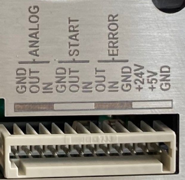
Table of contents

                    5.5.2         Menu structure: overview. . . . . . . . . . . . . . . . . . . . . . . . . . . . . . . . . . . . . . . . . . . . . . 31
                    5.5.3         Device setting parameters. . . . . . . . . . . . . . . . . . . . . . . . . . . . . . . . . . . . . . . . . . . . . 32
      5.6        GLP menu. . . . . . . . . . . . . . . . . . . . . . . . . . . . . . . . . . . . . . . . . . . . . . . . . . . . . . . . . . . . . . . . . . . . 36
      5.7        Program menu. . . . . . . . . . . . . . . . . . . . . . . . . . . . . . . . . . . . . . . . . . . . . . . . . . . . . . . . . . . . . . . . 36
                    5.7.1         Create program. . . . . . . . . . . . . . . . . . . . . . . . . . . . . . . . . . . . . . . . . . . . . . . . . . . . . . 36
                    5.7.2         Run program. . . . . . . . . . . . . . . . . . . . . . . . . . . . . . . . . . . . . . . . . . . . . . . . . . . . . . . . . 37
                    5.7.3         Change program. . . . . . . . . . . . . . . . . . . . . . . . . . . . . . . . . . . . . . . . . . . . . . . . . . . . . 37
                    5.7.4         Delete program lines . . . . . . . . . . . . . . . . . . . . . . . . . . . . . . . . . . . . . . . . . . . . . . . . . 37
                    5.7.5         Delete a program. . . . . . . . . . . . . . . . . . . . . . . . . . . . . . . . . . . . . . . . . . . . . . . . . . . . .38
                    5.7.6         Create a program with a starting time. . . . . . . . . . . . . . . . . . . . . . . . . . . . . . . . . . . 38
      5.8        Link menu. . . . . . . . . . . . . . . . . . . . . . . . . . . . . . . . . . . . . . . . . . . . . . . . . . . . . . . . . . . . . . . . . . . . 38
                    5.8.1         Create link. . . . . . . . . . . . . . . . . . . . . . . . . . . . . . . . . . . . . . . . . . . . . . . . . . . . . . . . . . . 39
                    5.8.2         Run link . . . . . . . . . . . . . . . . . . . . . . . . . . . . . . . . . . . . . . . . . . . . . . . . . . . . . . . . . . . . . 39
                    5.8.3         Delete link. . . . . . . . . . . . . . . . . . . . . . . . . . . . . . . . . . . . . . . . . . . . . . . . . . . . . . . . . . . 39

6.   Functionality tests. . . . . . . . . . . . . . . . . . . . . . . . . . . . . . . . . . . . . . . . . . . . . . . . . . . . . . . . . . . . . . . . . . . . 40

      6.1        Installation Qualification (IQ). . . . . . . . . . . . . . . . . . . . . . . . . . . . . . . . . . . . . . . . . . . . . . . . . . . . 40
      6.2        Operation Qualification (OQ) . . . . . . . . . . . . . . . . . . . . . . . . . . . . . . . . . . . . . . . . . . . . . . . . . . . 40

7.   Troubleshooting. . . . . . . . . . . . . . . . . . . . . . . . . . . . . . . . . . . . . . . . . . . . . . . . . . . . . . . . . . . . . . . . . . . . . . 41

      7.1        LAN. . . . . . . . . . . . . . . . . . . . . . . . . . . . . . . . . . . . . . . . . . . . . . . . . . . . . . . . . . . . . . . . . . . . . . . . . . 41
      7.2        Possible problems and solutions. . . . . . . . . . . . . . . . . . . . . . . . . . . . . . . . . . . . . . . . . . . . . . . . . 42
      7.3        System messages. . . . . . . . . . . . . . . . . . . . . . . . . . . . . . . . . . . . . . . . . . . . . . . . . . . . . . . . . . . . . . 43

8.   Maintenance and care . . . . . . . . . . . . . . . . . . . . . . . . . . . . . . . . . . . . . . . . . . . . . . . . . . . . . . . . . . . . . . . . 46

      8.1        Maintenance contract. . . . . . . . . . . . . . . . . . . . . . . . . . . . . . . . . . . . . . . . . . . . . . . . . . . . . . . . . . 46
      8.2        Cleaning and caring for the device. . . . . . . . . . . . . . . . . . . . . . . . . . . . . . . . . . . . . . . . . . . . . . . 46
      8.3        Checking the fittings. . . . . . . . . . . . . . . . . . . . . . . . . . . . . . . . . . . . . . . . . . . . . . . . . . . . . . . . . . . 46
      8.4        Flushing the pump. . . . . . . . . . . . . . . . . . . . . . . . . . . . . . . . . . . . . . . . . . . . . . . . . . . . . . . . . . . . . 47
      8.5        Maintaining the pump head. . . . . . . . . . . . . . . . . . . . . . . . . . . . . . . . . . . . . . . . . . . . . . . . . . . . . 47
                    8.5.1         Dismounting the pump head . . . . . . . . . . . . . . . . . . . . . . . . . . . . . . . . . . . . . . . . . . 47
                    8.5.2         Check valves. . . . . . . . . . . . . . . . . . . . . . . . . . . . . . . . . . . . . . . . . . . . . . . . . . . . . . . . . 49
      8.6         Maintaining the filter cartridge at pressure sensor. . . . . . . . . . . . . . . . . . . . . . . . . . . . . . . . . 51
                    8.6.1         Removing filter cartridge. . . . . . . . . . . . . . . . . . . . . . . . . . . . . . . . . . . . . . . . . . . . . . 51
                    8.6.2         Inserting a new filter cartridge. . . . . . . . . . . . . . . . . . . . . . . . . . . . . . . . . . . . . . . . . . 53

9.   Transport and storage. . . . . . . . . . . . . . . . . . . . . . . . . . . . . . . . . . . . . . . . . . . . . . . . . . . . . . . . . . . . . . . . . 55

      9.1        Putting the pump out of operation. . . . . . . . . . . . . . . . . . . . . . . . . . . . . . . . . . . . . . . . . . . . . . . 55
      9.2        Packing the device. . . . . . . . . . . . . . . . . . . . . . . . . . . . . . . . . . . . . . . . . . . . . . . . . . . . . . . . . . . . . 55
      9.3        Transporting the device . . . . . . . . . . . . . . . . . . . . . . . . . . . . . . . . . . . . . . . . . . . . . . . . . . . . . . . . 55
      9.4        Storing. . . . . . . . . . . . . . . . . . . . . . . . . . . . . . . . . . . . . . . . . . . . . . . . . . . . . . . . . . . . . . . . . . . . . . . 55

                                                    BlueShadow Pump 40P Instructions V7613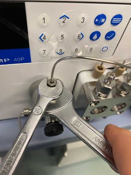
Table of contents

                       9.4.1         Storing the device. . . . . . . . . . . . . . . . . . . . . . . . . . . . . . . . . . . . . . . . . . . . . . . . . . . . 55
                       9.4.2         Storing the pump head. . . . . . . . . . . . . . . . . . . . . . . . . . . . . . . . . . . . . . . . . . . . . . . . 56

10. Disposal. . . . . . . . . . . . . . . . . . . . . . . . . . . . . . . . . . . . . . . . . . . . . . . . . . . . . . . . . . . . . . . . . . . . . . . . . . . . . 57

         10.1       AVV-Marking Germany. . . . . . . . . . . . . . . . . . . . . . . . . . . . . . . . . . . . . . . . . . . . . . . . . . . . . . . . . 57
         10.2       WEEE registration number. . . . . . . . . . . . . . . . . . . . . . . . . . . . . . . . . . . . . . . . . . . . . . . . . . . . . . 57
         10.3       Eluents and other operating materials. . . . . . . . . . . . . . . . . . . . . . . . . . . . . . . . . . . . . . . . . . . . 57

11. Technical data. . . . . . . . . . . . . . . . . . . . . . . . . . . . . . . . . . . . . . . . . . . . . . . . . . . . . . . . . . . . . . . . . . . . . . . . 58

         11.1       Solvent delivery. . . . . . . . . . . . . . . . . . . . . . . . . . . . . . . . . . . . . . . . . . . . . . . . . . . . . . . . . . . . . . . 58
         11.2       Communication. . . . . . . . . . . . . . . . . . . . . . . . . . . . . . . . . . . . . . . . . . . . . . . . . . . . . . . . . . . . . . . 59
         11.3       Technical parameters . . . . . . . . . . . . . . . . . . . . . . . . . . . . . . . . . . . . . . . . . . . . . . . . . . . . . . . . . . 59
         11.4       General . . . . . . . . . . . . . . . . . . . . . . . . . . . . . . . . . . . . . . . . . . . . . . . . . . . . . . . . . . . . . . . . . . . . . . 59

12. Chemical compatibility of wetted materials. . . . . . . . . . . . . . . . . . . . . . . . . . . . . . . . . . . . . . . . . . . . . . 60

         12.1       General . . . . . . . . . . . . . . . . . . . . . . . . . . . . . . . . . . . . . . . . . . . . . . . . . . . . . . . . . . . . . . . . . . . . . . 60
         12.2       Plastics. . . . . . . . . . . . . . . . . . . . . . . . . . . . . . . . . . . . . . . . . . . . . . . . . . . . . . . . . . . . . . . . . . . . . . . 60
                               Polyetheretherketone (PEEK). . . . . . . . . . . . . . . . . . . . . . . . . . . . . . . . . . . . . . . . . . . .                      60
                               Polyethylene terephthalate (PET, outdated PETP) . . . . . . . . . . . . . . . . . . . . . . . . . .                                     60
                               Polyimide (Vespel®). . . . . . . . . . . . . . . . . . . . . . . . . . . . . . . . . . . . . . . . . . . . . . . . . . . .              61
                               Ethylene-tetrafluorethylene copolymer (ETFC, Tefzel®). . . . . . . . . . . . . . . . . . . . . .                                        61
                               Perfluorethylenpropylen-Copolymer (FEP), Perfluoralkoxy-Polymer (PFA) . . . . . .                                                       61
                               Polyoxymethylene (POM, POM-H-TF). . . . . . . . . . . . . . . . . . . . . . . . . . . . . . . . . . . . .                               61
                               Polyphenylene sulfide (PPS) . . . . . . . . . . . . . . . . . . . . . . . . . . . . . . . . . . . . . . . . . . . .                     61
                               Polytetrafluorethylene (PTFE, Teflon®) . . . . . . . . . . . . . . . . . . . . . . . . . . . . . . . . . . . .                          61
                               Systec AF™. . . . . . . . . . . . . . . . . . . . . . . . . . . . . . . . . . . . . . . . . . . . . . . . . . . . . . . . . . .         61
                               Polychlortrifluorethylene (PCTFE, Kel-F®). . . . . . . . . . . . . . . . . . . . . . . . . . . . . . . . . .                            62
                               Fluorinated rubber (FKM). . . . . . . . . . . . . . . . . . . . . . . . . . . . . . . . . . . . . . . . . . . . . . .                   62
                               Perfluorinated rubber (FFKM) . . . . . . . . . . . . . . . . . . . . . . . . . . . . . . . . . . . . . . . . . . .                      62
         12.3       Non-metals. . . . . . . . . . . . . . . . . . . . . . . . . . . . . . . . . . . . . . . . . . . . . . . . . . . . . . . . . . . . . . . . . . . 62
                               Diamond-like carbon (DLC) . . . . . . . . . . . . . . . . . . . . . . . . . . . . . . . . . . . . . . . . . . . . .                     62
                               Ceramic . . . . . . . . . . . . . . . . . . . . . . . . . . . . . . . . . . . . . . . . . . . . . . . . . . . . . . . . . . . . .       62
                               Alumina (Al2O3) . . . . . . . . . . . . . . . . . . . . . . . . . . . . . . . . . . . . . . . . . . . . . . . . . . . . . . .           62
                               Zirconium oxide (ZrO2) . . . . . . . . . . . . . . . . . . . . . . . . . . . . . . . . . . . . . . . . . . . . . . . . .                62
                               Sapphire. . . . . . . . . . . . . . . . . . . . . . . . . . . . . . . . . . . . . . . . . . . . . . . . . . . . . . . . . . . . .       62
                               Ruby. . . . . . . . . . . . . . . . . . . . . . . . . . . . . . . . . . . . . . . . . . . . . . . . . . . . . . . . . . . . . . . . .   62
                               Mineral wool. . . . . . . . . . . . . . . . . . . . . . . . . . . . . . . . . . . . . . . . . . . . . . . . . . . . . . . . . .         63
                               Glass, glass fibre, quartz, quartz glass. . . . . . . . . . . . . . . . . . . . . . . . . . . . . . . . . . . .                         63
         12.4       Metals. . . . . . . . . . . . . . . . . . . . . . . . . . . . . . . . . . . . . . . . . . . . . . . . . . . . . . . . . . . . . . . . . . . . . . . .63
                               Stainless steel . . . . . . . . . . . . . . . . . . . . . . . . . . . . . . . . . . . . . . . . . . . . . . . . . . . . . . . . 63
                               Hastelloy®-C. . . . . . . . . . . . . . . . . . . . . . . . . . . . . . . . . . . . . . . . . . . . . . . . . . . . . . . . . . 63
                               Titanium, titanium alloy (TiA16V4). . . . . . . . . . . . . . . . . . . . . . . . . . . . . . . . . . . . . . . . 63

13. Repeat orders. . . . . . . . . . . . . . . . . . . . . . . . . . . . . . . . . . . . . . . . . . . . . . . . . . . . . . . . . . . . . . . . . . . . . . . . 64

                                                       BlueShadow Pump 40P Instructions V7613
Table of contents

13.1   Devices . . . . . . . . . . . . . . . . . . . . . . . . . . . . . . . . . . . . . . . . . . . . . . . . . . . . . . . . . . . . . . . . . . . . . . 64
13.2   Spare parts . . . . . . . . . . . . . . . . . . . . . . . . . . . . . . . . . . . . . . . . . . . . . . . . . . . . . . . . . . . . . . . . . . . 64

                                         BlueShadow Pump 40P Instructions V7613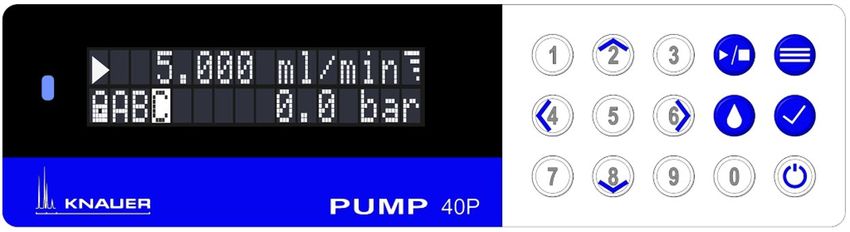
1

1. General
             1.1       About these instructions
             These operating instructions enable the safe and efficient operation of
             the device. The user must have carefully read and understood these
             operating instructions before starting any work.
             The basic prerequisite for safe operation is compliance with all safety
             instructions (see chapter 2 on page 3). In addition to the safety and
             warning instructions in these operating instructions, the local accident
             prevention regulations and the national industrial safety regulations
             apply.
             These operating instructions are an integral part of the device. It must be
             kept in the immediate vicinity of the device and accessible to the user at
             all times.
             You can download these and other instructions from the KNAUER web-
             site: www.knauer.net/library

             1.2       Signal words
             Possible dangers related to the device are distinguished in personal and
             material damages.

              Symbol                Meaning
                                    DANGER (red) indicates a highly hazardous situa-
                                    tion. If not avoided, it will result in death or serious
                                    injury.

                                    WARNING (orange) indicates a hazardous situa-
                                    tion. If not avoided, it could result in death or
                                    serious injury.

                                    CAUTION (yellow) indicates a moderate hazardous
                                    situation. If not avoided, it could result in minor or
                                    moderate injury.

                                    NOTICE (blue) is used to address issues which are
                                    not related to physical injury.

             1.3       Additional typographical conventions
             Note: Specific information are prefixed with the word „Note” and an
             information icon.

             Note: This is an example.

                   BlueShadow Pump 40P Instructions V7613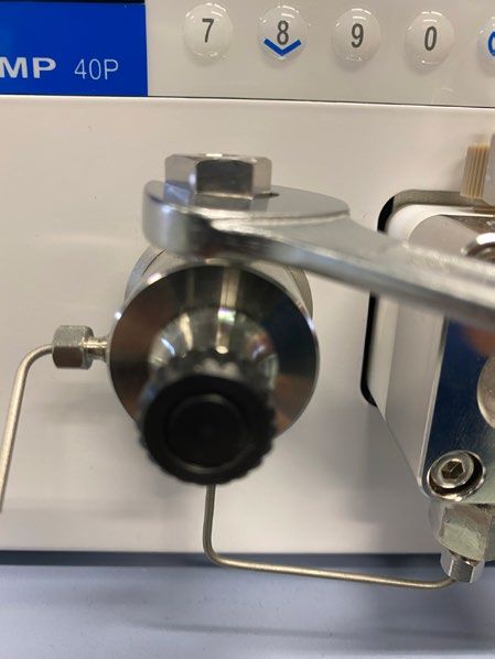
2 General
1.4 Legal information
1.4.1 Liability limitation
The manufacturer is not liable for the following issues:
Non-compliance of these instructions
Non-observance of necessary safety precautions
Improper use
Operation of the device by unqualified personnel (see chapter 2.2 on
page 3)
Use of non-approved spare parts
Technical changes by the user such as opening the device and unaut-
horized modifications
Violations of General Terms and Conditions (GTC)
1.4.2 Transport damage
The packaging of our devices provides the best possible protection
against transport damage. However, check the packaging for transport
damage. In case you notice any damage, inform the Technical Support
and the shipping company within three workdays.
1.4.3 Warranty conditions
For information on warranty please refer to our general terms and condi-
tions on the website: www.knauer.net/terms
1.4.4 Warranty seal
A blue or orange warranty seal is affixed to some devices.
A blue seal is used by KNAUER’s Manufacturing or Customer Support
for devices to be sold.
After repair, service technicians attach an orange seal onto the identi-
cal position.
After repair, the service technician affixes an orange seal in the same pla-
ce. If unauthorised persons tamper with the device or if the seal is dama-
ged, the warranty will lapse.
1.4.5 Declaration of conformity
The declaration of conformity is enclosed as a separate document with
the product and can be obtained online:
www.knauer.net/en/Support/Declarations-of-conformity
BlueShadow Pump 40P Instructions V7613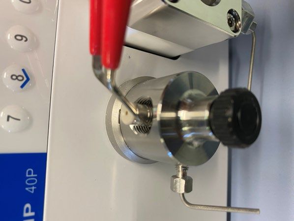
3
2. Basic safety instructions
The device has been developed and constructed in such a way that ha-
zards arising from its intended use are largely excluded. Nevertheless, the
following safety instructions must be observed in order to exclude residu-
al hazards.
2.1 Intended use
Only use the device for applications that fall within the range of the inten-
ded use. Otherwise, the protective and safety equipment of the device
could fail.
2.1.1 Operating ranges
The device is intended to be used indoors for chromatographic
applications.
Note: The device can also be used for dosing applications if the
Dosing mode is selected and the maintenance cycles are followed. A
warning message appears on the device display when the maximum
operating time is reached.
2.1.2 Foreseeable misuse
Refrain from the use of the device for the following purposes or
conditions:
Medical purposes. The device is not approved as a medical product.
Operating outdoors. Otherwise, the manufacturer does not guarantee
the functionality and safety of the device.
Operation in potentially explosive areas without special and additio-
nal explosion protection. Contact the KNAUER Customer Support for
more information.
2.2 User qualification
The users are qualified to handle the device if all of the following points
apply:
They have at least a basic knowledge of liquid chromatography.
They have knowledge about the properties of the used solvents and
their health risks.
They are trained for the special tasks and activities in the laboratory
and know the relevant standards and regulations.
Due to their technical training and experience, they can unders-
tand and carry out all the work described in the operating instruc-
tions on the instrument and recognize and avoid possible dangers
independently.
Their ability to react is not impaired by the consumption of drugs,
alcohol or medication.
They have participated in the installation of an instrument or training
by KNAUER or an authorized company.
BlueShadow Pump 40P Instructions V76134 Basic safety instructions
If users do not meet these qualifications, they must inform their
supervisors.
2.3 Operator responsibility
The operator is any person who operates the device himself or leaves it to
a third party for use and who bears the legal product responsibility for the
protection of the user or third parties during operation.
The obligations of the operator are listed below:
Know and follow the applicable work safety regulations.
Identify hazards arising from the working conditions at the place of use
in a risk assessment.
Set up operating instructions for the operation of the device.
Regularly check whether the operating instructions correspond to the
current status of the regulations.
Clearly regulate and specify responsibilities for installation, operation,
troubleshooting, maintenance and cleaning and set clear rules.
Ensure that all personnel who work with the device have read and un-
derstood these operating instructions.
Train the personnel who work with the device at regular intervals and
inform them about the dangers.
Provide the necessary safety equipment to the employees working
with the unit (see section below).
2.4 Personal safety equipment
The protective measures required in the laboratory must be observed
and the following protective clothing worn during all work on the device:
Safety glasses with side protection
Protective gloves in accordance with the prevailing ambient conditions
and used solvents (e.g. heat, cold, protection against chemicals)
Lab coat
Personalised protective safety equipment which is specified in the
particular laboratory
BlueShadow Pump 40P Instructions V7613Basic safety instructions 5
2.5 Working with solvents
2.5.1 General requirements
The user is trained for handling different solvents.
Note recommended solvents and concentrations in these instructions
in order to avoid personal injury or damage to the device. For exam-
ple, certain chemicals may cause PEEK capillaries to swell or burst (see
chapter 12 on page 60).
Note that organic solvents are toxic above a certain concentration. For
handling hazardous solvents see the following section.
Mobile phases and samples may contain volatile or combustible sol-
vents. Avoid the accumulation of these substances. Ensure good ven-
tilation of the installation site. Avoid open flames and sparks. Do not
operate the instrument in the presence of flammable gases or vapors.
Only use solvents which do not self-ignite under given conditions. This
applies especially to the use of a thermostat where liquids could get
onto hot surfaces in the interior.
Degas solvents before use and observe their purity.
2.5.2 Contamination by health-threatening solvents
Contamination with toxic, infectious or radioactive substances poses
a hazard for all persons involved during operation, repair, sale, and dis-
posal of a device.
All contaminated devices must be properly decontaminated by a spe-
cialist company or the operating company before they can be recom-
missioned, repaired, sold, or disposed (see chapter 10 on page 57).
2.5.3 Avoiding leakage
Risk of electrical shock or short circuit if solvents or other liquids leak into
the interior of the device. You can avoid a leakage through the following
measures:
Tightness: Visually check the device or system regularly for leaks.
Solvent tray: The use of a solvent tray prevents liquids get from the
bottles into the inside of the device.
Eluent lines: Install capillaries and hoses in such a way that, in case of a
leak, liquids cannot get into the interior of the devices underneath.
In case of leakage: Switch off the system. Only take the device into
operation if the cause of the leak has been resolved (see chapter 8 on
page 46).
BlueShadow Pump 40P Instructions V76136 Basic safety instructions
2.6 Specific environments
2.6.1 Earthquake-endangered areas
In earthquake-endangered areas, do not stack more than 3 devices on
top of each other. Otherwise there is risk of injury due to falling devices
or loose parts.
2.6.2 Explosive environment
Never use the system in potentially explosive atmospheres without
appropriate protective equipment. For more information, contact the
KNAUER Customer Support.
2.6.3 Cooling room
You may operate the device in a cooling room. To prevent condensation,
note the following instructions:
Allow the device to acclimatize for min. 3 hours before taking it into
operation.
After taking into operation, the device should stay switched on.
Avoid temperature fluctuations.
2.6.4 Wet room
The device must not be operated in wet rooms.
2.7 Maintenance, care and repair
Avoiding electric shock: Before performing any maintenance and ser-
vice work, disconnect the device from the power supply.
Tools: Use only tools recommended or prescribed by the
manufacturer.
Spare parts and accessories: Only use original parts and accessories
made by KNAUER or a company authorized by KNAUER.
PEEK fittings: Use PEEK fittings only for a single port or brand-new
PEEK fittings in order to avoid dead volume or not exactly fitting
connections.
Column care: Follow KNAUER or other manufacturer‘s instructions on
caring for the columns (see www.knauer.net/columncare)
Used capillaries: Do not use any used capillaries elsewhere in the
system in order to avoid dead volumes, not exactly fitting connections
and spreading contamination.
Safety features: The device may only be opened by the KNAUER Cus-
tomer Support or any company authorized by KNAUER (see chapter
1.4.1 on page 2).
For more information visit the KNAUER website:
www.knauer.net/hplc-troubleshooting
BlueShadow Pump 40P Instructions V7613Basic safety instructions 7
2.8 Service request form and decontamination
report
Devices which are shipped without the completed document “Service
request form and decontamination report” will not be repaired. If you
would like to return a device to KNAUER, make sure to enclose the com-
pleted document: www.knauer.net/servicerequest
BlueShadow Pump 40P Instructions V76138
3. Product information
3.1 Views
3.1.1 Front view
Legend
1 Display 1 2 4 5
2 Pressure sensor
3 Ventilation screw
4 Keypad
5 Tube connections for
the piston backflushing
6 Pump head
3 6
Fig. 1: Front view
3.1.2 Rear view
Legend 1 2 3 4
1 Warranty seal
2 Space for rear label
(with serial number)
3 Fan opening
4 Warning 1
5 Power switch
6 Power supply
7 CE-Mark
8 Remote connector 5
9 RS-232 Port
6
blWarning 2
bmLAN connection
bnEvents connector
bn bmbl 9 8 7
Fig. 2: Rear view
BlueShadow Pump 40P Instructions V7613Product information 9
3.2 Features
Dual-piston technology combined with optimized electronic
pulsationdampening and compressibility compensation
Liquid transport with low pulsation, stable flow rate and high flow
accuracy
Pump head made of stainless steel or with ceramic inlays
Automatic piston backflushing
High physical and chemical stability
Direct pump control via analog and digital signals
Control with chromatography software
3.3 Pump heads
Note: Due to the new drive used in the pump, pump heads of older se-
ries cannot be used any more.
Available pump head types:
Pump head 10 ml, for use in analytical applications, standard version
made of stainless steel. Ceramic inlays for biocompatible applications.
Stainless steel pump head for high-temperature applications.
Pump head 50 ml, for use in semi-preparative applications, standard
version made of stainless steel. Ceramic inlays for biocompatible appli-
cations. Stainless steel pump head for high-temperature applications.
Labeling on pump heads The front of the pump head is labeled with the max. pumping capacity
(10 ml or 50 ml). Pump heads with inlays carry additional material labels
(SST for stainless steel, C for ceramic).
Automatic pump head The pump automatically recognizes the pump head by means of an RFID
recognition chip.
3.4 RFID recognition
The pump head is equipped with an RFID chip. It is used to monitor and
save all important parameters and settings of the pump and pump head.
The RFID technology offers the following advantages:
Automatic detection of all important pump head parameters by means
of radio signals (radio frequency identification), by the pump software
or the chromatography software:
- Pump head type
- Serial number and year of manufacture
- Number of cycles and operating times
- Limit values of the pump head parameters
All measuring data archived in accordance with GLP (good laboratory
practice)
Transfer of all data to the software and pump display
BlueShadow Pump 40P Instructions V761310 Product information
3.5 Symbols and signs
The following symbols and signs can be found on the device:
Symbol Meaning
High-voltage hazard
Electrostatic discharge hazard, damages to
system, device, or components can occur.
A device marked with CE fulfills the product spe-
cific requirements of European directives. This is
confirmed in a Declaration of Conformity.
A warranty seal is affixed to some devices. For
more information see chap. 1.4.4 on p. 2.
3.6 Scope of delivery
Note: Only use original parts and accessories made by KNAUER or a
company authorized by KNAUER.
Power cable
BlueShadow Pump 40P with pump head
Accessories kit pump 40P
Accessories kit pump head
Applicable documents:
User manual
Installation Qualification
Declaration of Conformity
BlueShadow Pump 40P Instructions V761311
4. Installation and initial startup
Before you determine the operation site, read the chapter “Technical
data” (see chapter 11 on page 58). There you will find all device-speci-
fic information on power supply, ambient conditions and humidity.
Note: The intended use be ensured only if the requirements for ambient
conditions of the operating environment are met.
4.1 Unpacking
Process
Procedure 1. Place the packaging in such a way that the lettering on the label is
in the correct position.
2. Check the packaging, the device and the accessories for transport
damage.
3. Check the scope of delivery. In the event of incomplete delivery,
contact Technical Support immediately.
4. When lifting, carrying or moving the device, grab the unit only
from below on the sides. Do not hold onto front cover or leak tray,
as these parts are loosely attached to the device.
Next steps Keep the included packing list for repeat orders.
Keep the original packaging for safe storage or transportation.
4.2 Ambient conditions
4.2.1 Operation site
Observe the following requirements for the operation site so that the
measurement results are not influenced:
Place on a firm, level and straight surface.
Protect against direct sunlight.
Do not expose to air drafts such as air conditioning systems.
Do not set up the to other machines that cause floor vibrations.
Keep from high frequency sources.
Ensure adequate ventilation (see chapter 4.2.3 on page 12).
Avoid temperature fluctuations (see chapter 4.2.2 on page 11).
4.2.2 Ambient temperature
If the ambient temperature of the device is abruptly changed (e.g. when
it is installed in a cooling chamber), condensation will form inside the
device and may cause damage to the device. Allow the device to accli-
mate for 3 h, before it is connected to the power supply and taken into
operation.
BlueShadow Pump 40P Instructions V761312 Installation and initial startup
4.2.3 Space requirements
Make sure that the power plug on the power supply (wall socket or
power strip) is always accessible, so that the device can be disconnec-
ted from the power supply.
Ensure adequate ventilation around the device, otherwise it may over-
heat and malfunction:
- Min. 5 cm distance if another device is set on one side.
- Min. 10 cm distance if further devices are set on both sides.
- At least 15 cm to the cooler fan on the rear.
4.3 Power supply
4.3.1 Power supply requirements
Failure-free power supply: For failure-free operation, the electrical
voltage must be free of fluctuations, residual currents, voltage peaks
and electromagnetic interference. The device must receive sufficient
voltage and reserve capacity.
Check voltage: Only connect devices to a power supply whose voltage
corresponds to the permissible voltage of the device.
Power consumption: The nominal power of the connected devices
must not exceed 50 % of the highest connected power capacity, since
higher currents can flow briefly when the device is switched on.
Main connection: The electrical power supply at the operation site
must be connected directly to the nearest main power connection.
Grounding: The connectors for the voltage must be grounded
accordingly.
4.3.2 Power supply cables and plugs
Original parts: For power supply, use the supplied power cable and
plug to meet the specifications which are described in the chapter
“Technical data” (see chapter 11 on page 58). Detachable power
cables are not allowed to be replaced with other cable types.
Country-specific plugs: Before switching on the device, check whether
the supplied plug is approved for your country. Overview of the de-
vice- and country-specific plug types from KNAUER:
www.knauer.net/plugs.
Power strips: If several devices are connected to one power strip, al-
ways consider the maximum power consumption of each device.
Access to power supply: Make sure that the power plug on the pow-
er supply (wall socket or power strip) is always accessible, so that the
device can be disconnected easily from the power supply.
Damaged power supply cables and plugs: For safety reasons, dama-
ged or faulty cables and plugs must not be used to connect the device
to the power supply. Replace defective cables and plugs only with
KNAUER accessories.
BlueShadow Pump 40P Instructions V7613Installation and initial startup 13
4.4 Electric connections
Use the Events and Remote pin header to connect the pump with ex-
ternal devices.
Use the LAN connection to connect the pump with external devices
within a network.
Alternatively, connect the pump to a computer with the RS-232 port.
Electronic defect
Electrostatic discharge can destroy the electronics.
Wear a protective bracelet against electrostatic discharge and ground.
4.4.1 Connecting cables to the pin header
To control one device through another, the pin header is used. To use
remote control, you have to connect cables to the pin header. The single
ports are used to exchange control signals.
The device is switched off.
The power plug is pulled.
Tool Depressor tool
Electronic defect
Connecting cables to the multi-pin connector of a switched on device
causes a short circuit.
Turn off the device before connecting cables.
Pull the power plug.
1
2
3
Fig. 3: Depressor tool
BlueShadow Pump 40P Instructions V761314 Installation and initial startup
Process
1. Push the depressor tool 3 into an upper small opening on the
front of the terminal strip 1.
2. Lead the cable into the opening 2 below the inserted operating
tool.
3. Remove the depressor tool.
Next steps Check if the cables are firmly connected.
Push the terminal strip onto the pin header.
Finish the installation.
Put the device into operation.
4.4.2 Remote connector
For receiving start, control and error signals from external devices
For sending start, control and error signals to external devices
Fig. 4: Remote connector
BlueShadow Pump 40P Instructions V7613Installation and initial startup 15
Signal Explanations
ANALOG: Analog output signal reflecting either the measu-
OUT red system pressure or a control voltage for
pump B.
The output range can be set to values of max. 1, 2,
5 and 10 V.
ANALOG: IN Analog input signal for controlling the flow rate, e.g.:
1 V for 1 ml/min in the case of the 10 ml pump
head
1 V for 5 ml/min in the case of the 50 ml pump
head.
START: OUT Output is active for 500 ms when the pump starts.
START: IN Device starts after signal (short circuit to GND) of an
external device. During software control an electronic
trigger is sent via LAN.
ERROR: OUT Output is active until the Error condition has been
eliminated.
ERROR: IN A voltage of 0 V against GND stops the pump.
4.4.3 Events connector
Sending control signals (Events) to external devices
Opening and closing contacts
Activating 500 ms pulses
Fig. 5: Events connector
BlueShadow Pump 40P Instructions V761316 Installation and initial startup
4.5 Connecting capillaries and fittings
The capillary connecting the pump head and flushing valve is already
pre-installed. Only the solvent bottles have to be connected and the
pump has to be integrated into the flow of the HPLC system.
4.5.1 Connecting the solvent bottles
To connect the solvent bottles, tubing with pre-installed solvent filters is
used. The tubing is connected to the device with flangeless fittings.
Note: Do not use any tools to tighten the fittings.
Procedure Process Figure
1. Slide the flangeless fitting 1
over the tubing.
2. Slide the lock ring 2 over the
tubing.
3. Cap with the sealing ring 3.
Note the direction of the lock
ring, otherwise the sealing
ring could be damaged. The
thicker end of the lock ring
1 2 3
must point into the direction Fig. 6: Setup of a flangeless
of the fitting. fitting
4. Manually fasten the flangeless
fitting 4 to the device.
4
Fig. 7: Fully assembled
flangeless fitting
4.5.2 Connecting the pump head to the solvent
Check that all fittings are tight.
Isocratic system: Connect the solvent reservoir either via an external
degasser or directly to the pump.
Note: The manufacturer generally recommends the use of a degassing
module to reliably deliver the solvent as eluent.
Prerequisites The device has been switched off.
The power plug has been pulled.
The front cover has been removed.
Material Flangeless fitting
BlueShadow Pump 40P Instructions V7613Installation and initial startup 17
Device defect
Damage to pump head, device or system when inlet and outlet of the
pump head are blocked.
Remove the cap fittings from the inlet and outlet of the pump head
prior to use.
Procedure Process Figure
1. Slide the flangeless fitting
over the tubing.
2. Insert the tubing into the free
inlet 1 on the bottom of the
pump head.
3. Tighten the fitting by hand.
1
Fig. 8: Solvent line on pump
head
Next step Integrate the pump into the HPLC system.
BlueShadow Pump 40P Instructions V761318 Installation and initial startup
4.6 Control
The pump can be operated in two ways:
Via the pin header (Analog-In connection with WAGO plug)
As part of a LAN, via the LAN connector of the router
All connectors for external control are located on the rear side of the
pump.
Legend
1 2 3 4
1 Events connector
2 LAN connector
3 RS-232 port
4 Remote connector
Fig. 9: Connectors on rear side
Note: HPLC devices from KNAUER only work with IP addresses, which
have been assigned by IPv4. IPv6 is not supported.
This chapter describes how to set up a chromatography system in a local
area network (LAN) and how a network administrator can integrate this
LAN into your company network. The description applies to the operating
system Windows® and all conventional routers.
Note: When using PurityChrom®, static IP addresses are needed
(see chapter 4.7 on page 21).
4.6.1 Setting up LAN
To set up a LAN, we recommend to use a router. That means the following
steps are required:
Process
Procedure 1. On the computer, go to the control panel and check the LAN
properties.
2. Hook up the router to the devices and the computer.
3. Set up the router for the computer network.
4. Install the chromatography software.
5. Switch on the device and run the chromatography software.
Next steps Configure LAN properties (see chapter 4.6.2 on page 19).
BlueShadow Pump 40P Instructions V7613Installation and initial startup 19
4.6.2 Configuring LAN settings
The LAN uses only one server (which is normally the router) from that the
devices automatically receive their IP address.
Prerequisites In Windows, power saving, hibernation, standby, and screen saver
must be deactivated.
In case you use an USB-to-COM box, the option "Allow the computer
to turn off this device to save power" in the device manager must be
deactivated for all USB hosts.
Applies to all LAN devices: Disable the setting for the network adapter
in device manager "Allow the computer to turn off this device to save
power”.
Process
Procedure 1. In Windows, open .
2. Double-click on .
3. Click on the button .
4. Select .
5. Click on the button .
6. Check the settings in the tab . The correct settings for
the DHCP client are:
a) Obtain an IP address automatically
b) Obtain DNS server address automatically
7. Click on the button .
Next steps Connect devices (see chapter 4.6.3 on page 19).
4.6.3 Connecting devices with LAN
A router 2 has several LAN ports 3
and one WAN port 4 that can be
used to integrate the LAN into a wide area network (WAN), e.g. a com-
pany network or the Internet. In contrast, the LAN ports serve to set up a
network from devices 1
and a computer 5. To avoid interference, we
recommend operating the chromatography system separately from the
company network.
Note: You will find patch cables for each device and the router in the
accessories kit. To connect the router to a LAN, an additional patch cable
is required, which is not supplied within the scope of delivery.
BlueShadow Pump 40P Instructions V761320 Installation and initial startup
Legend 1 2 3 4 5
1 Devices
2 Router
3 LAN ports
4 WAN/Internet
connection
5 Computer
Fig. 10: Connect devices with LAN
Prerequisites The computer is switched off.
There is a patch cable for each device and the computer.
Process
Procedure 1. Use the patch cable to connect the router and the computer.
Repeat this step to connect all devices.
2. With additional patch cables, connect all devices individually with
the router.
3. Use the power supply to connect the router to the mains power
system.
Next steps Set the router properties (see chapter 4.6.4 on page 20).
4.6.4 Configuring the router
The router is preset at the factory. Information about address, user name
and password is noted in the router manual: www.knauer.net/router.
Process
Procedure 1. To open the router configuration, start your Internet browser and
enter the IP address (does not apply for all routers).
2. Enter user name and password.
3. Configure the router as DHCP server.
4. In the router configuration, check the IP address range and make
changes if necessary.
Note: If the IP address range has been changed, it is essential to note
this information on the router.
Result Once the router has assigned IP addresses to all devices, the chromato-
graphy software can be used to remotely control the system.
4.6.5 Integrating LAN into the company network
A network administrator can integrate the LAN into your company net-
work. In this case you use the WAN port of the router.
Prerequisites There is a patch cable for the connection.
BlueShadow Pump 40P Instructions V7613Installation and initial startup 21
Process
Procedure 1. Make sure that there is no overlap between the IP addresses of the
router and the corporate network.
2. In case of an overlap, change the IP address range of the router.
3. Use the patch cable to connect the router WAN port to the compa-
ny network.
4. Restart all devices, including the computer.
Result The LAN is now integrated into the company network.
4.6.6 Controlling several systems separately in LAN
Devices connected to a LAN communicate through ports, which are part
of the IP address. If more than one chromatography systems are connec-
ted to the same LAN and you plan on controlling them separately, you
can use different ports to avoid interference. Therefore, the port number
for each device must be changed and this same number must be entered
into the device configuration of the chromatography software. We recom-
mend to use the same port number for all devices in the same system.
Note: The port is set to 10001 at the factory. You must use the same num-
bers in the device configuration of the chromatography software as in the
device, otherwise the connection fails.
Process
Procedure 1. Find out port number and change it on the device.
2. Enter the port number in the chromatography software.
Result The connection is established.
4.7 Setting IP addresses via software
Note: Check the IT security standards for your lab before intervening in
the LAN settings.
PurityChrom® Static IP addresses are required to run certain chromatography software,
e.g. Purity Chrom®. For a comprehensive overview on how to set static IP
addresses for PurityChrom®, refer to the document „PurityChrom® Instal-
lation Guide“ on the PurityChrom® installation CD.
For Mobile Control and Firmware Wizard, it is possible to set a fixed (sta-
tic) or dynamic (DHCP) IP address via software.
4.7.1 Firmware Wizard: Setting a static IP address
Note: More information about LAN settings can be found in the Mobile
Control Software Instructions in the chapter "Firmware Wizard” (docu-
ment no. V6851-2).
BlueShadow Pump 40P Instructions V761322 Installation and initial startup
Legend
1 Text box for serial
number of the
device
1
2 Setting IP address
manually
2
3 Text box for IP
address 3
4 Text box for subnet
mask & gateway 4
5 Confirm changes
5
Fig. 11: Network settings in Firmware Wizard
Prerequisites The device is switched on.
Firmware Wizard is installed and running.
The connection between Firmware Wizard and the device has been
established.
Process
Procedure 1. In Firmware Wizard, click .
2. The window opens. Enter serial
number of the device into the text field 1
.
3. Select option 2.
4. Enter the IP address into the text field 3.
5. Optionally, adjust subnet mask and gateway 4.
6. Click 5 to accept changes.
7. Restart the device (recommended).
Result The device is now accessible via the static IP address.
BlueShadow Pump 40P Instructions V7613Installation and initial startup 23
4.7.2 Firmware Wizard: Setting a dynamic IP address
Prerequisites The device is switched on.
Firmware Wizard is installed and running.
The connection between Firmware Wizard and the device has been
established.
Process
Procedure 1. In Firmware Wizard, click .
2. The window opens. Enter serial
number of the device into the text field 1
.
3. Select option 2.
4. Click 5 to accept changes.
5. Restart the device (recommended).
Result The device is now accessible via a dynamic IP address.
BlueShadow Pump 40P Instructions V761324
5. Operation
5.1 Initial operation
Use this checklist to check if the pump is ready for initial operation:
Device is positioned in the correct location.
The power plug has been connected.
If the device is part of an HPLC system, you should also note the
following:
The network connection to the router is established.
The chromatography software has been installed by KNAUER or a
company authorized by KNAUER.
The capillaries have been connected.
Note: Prior to switching on the pump, you should purge it to remove air
from capillaries and tubings (see chapter 5.2 on page 25).
5.1.1 Pump head running-in
Note: It is mandatory to perform a running-in procedure after a pump
head maintenance, or if new pump heads are installed on a pump.
All pump heads were filled with isopropanol prior to delivery. Make
sure to connect the correct solvent as described in the specification
table found in the supplement „Running-In procedure for pump heads“
(V6894).
If a pump was not in operation for a long time, e.g. after shipment, a
running-in procedure might be necessary to obtain the best pump per-
formance. The pump head underwent this procedure during the manu-
facturing process.
If the pump is performing within specification, or during intensive opera-
tion, it is not necessary to perform this procedure.
Component defect
Damage to the pump head in case running-in procedure was not per-
formed correctly.
Set the correct backpressure and flowrate for the running-in procedu-
re of the pump head. Specific running-in parameters and the general
procedure can be found in the supplement „Running-in procedure for
pump heads (V6894)“.
Device defect
If the pump is operated only with pure distilled water, significantly hig-
her wear of the piston and the piston seals can be expected.
If possible, only operate the pump with water together with the added
additive or modifier.
BlueShadow Pump 40P Instructions V7613Operation 25
5.1.2 Isocratic operating mode
Analysis without gradients
The solvent composition is constant during the analysis.
The solvent can be recycled.
5.1.3 Optimizing HPLC separations
To make your HPLC separations as efficient as possible, pay close atten-
tion to the following:
Task Explanation
Avoiding additional Once they have been used, never re-use ca-
dead volumes pillaries in other areas of the HPLC system.
Only use a given PEEK fitting for one specific
port and never re-use it for other ports. Al-
ways install new PEEK fittings on each sepa-
rate port.
Using special Use special columns and follow the manufactu-
columns rer‘s instructions on caring for the columns.
Checking for Regularly check for clogged capillaries – test
clogged capillaries back pressure without column!
Using filtered Use ultra-pure, filtered solvents – gradient
solvents grade – for the HPLC.
Filtration of substances to be analyzed.
Use of inline filters.
5.2 Purging the pump
Column defect
Damage to the column due to purging.
Open the venting screw.
Remove the column.
Before the pump can be used, it must be purged to remove excess air in
the capillaries.
Flush the pump in the following cases:
When is purging At initial startup to eliminate air bubbles in hoses and capillaries.
required? When changing solvents.
After using buffer solutions to eliminate salt residues.
Before turning off, if you do not plan to restart the device within
shortly.
Prerequisites The installation has been completed.
The capillaries and tubings have been connected.
BlueShadow Pump 40P Instructions V761326 Operation
The pump has been switched on and is in „flow mode“.
Tool Syringe with Luer lock
Use the purging solvent used in the following applications.
Note: The purging process may take a while during initial operation be-
cause the solvent tubes are filled with liquid for the first time.
Note: If a buffer solution is used, pay attention to choose a solvent for
purging in which the buffer solution is soluble.
Procedure Process Figure
1. Open the venting screw 2of
the pressure sensor.
2. Connect the syringe with the
1
silicone tubing to the
outlet 1. 2
3. Press the purging button
to open the purging mode
and select respective gra-
dient and flow.
4. With the syringe, extract fluid
through the purge port 1. Fig. 12: Venting screw of the
5. If the extracted fluid flows pressure sensor
continuously, stop suc-
tion and close the venting
screw 2.
The purging process of the pump is limited to a maximum pressure of
5 MPa. If this value is exceeded during the purging process, the pump
switches off automatically. If you are using very small hoses and capilla-
ries, the pressure can be too high.
5.2.1 Piston backflushing
The pump is equipped with automatic piston backflushing. It increases
the service life of the seals and pistons, and removes contaminants from
the area behind the seals.
Functional principle The piston backflushing function automatically flushes the rear piston
area of the pump head upon switch-on and in continuous mode.
Upon switch-on: The rear piston area of the pump head is automatical-
ly flushed for 8 seconds.
In continuous mode: The rear piston area of the pump head is flushed
automatically every two hours, for 15 seconds.
Recommended Select a suitable solvent in the backpiston flushing. The solvent used
purging solution for the flushing depends on the application and the used solvent in the
pump:
BlueShadow Pump 40P Instructions V7613Operation 27
Solvent in the pump Piston backflushing
Reverse phase solvents 50% isopropanol or ethanol with
50 % water (v/v)
Normal phase solvents 100 % isopropanol
Buffers with high salt Rinse with water containing
concentrations 5% ethanol or isopropanol.
Legend
1 Outlet from the pump 1
head to the
solvent bottle
2 Inlet from the solvent
bottle to the flush
2
pump
3 Outlet from the flush 3
pump to the pump
head
Fig. 13: Connectors for piston backflushing
5.3 Switch on and self test
Procedure 1. Switch on the pump.
2. The display shows Initialization. The device runs a self test.
3. Wait until the self test has been completed.
4. After the test has been successfully completed, the most recently ac-
tive program will be displayed.
5.4 Operating with LC display and keypad
The LC display operation of the pump is suitable for the following tasks:
Monitoring device functions
Using special programs for laboratory work:
— Flushing program
— Standby and Wake up (WU) program
— Program sequences (Link Menu)
— Checking the system status as part of quality assurance measures
in accordance with Good Laboratory Practices (GLP menu)
BlueShadow Pump 40P Instructions V761328 Operation
Legend
1 Status LED 12 5 6 7
2 Status Start/Stop
3 Remote control
4 Gradient modus
5 Parameters/Values
6 RFID recognition of
the pump head
7 Keypad 3 4
Fig. 14: LC display and keypad
5.4.1 LED status
The status of the device is indicated by an LED on the front side. The co-
lor of the LED shows the current status.
LED Status
Green Pump is ready (idle
status).
Green flashing Pump is running.
Yellow Firmware upload in
progress.
Yellow flashing Device initialization
Red A serious error occured.
Red flashing An acknowledgeable
error occured.
Blue Device in standby
5.4.2 RFID icon
The status of a RFID valve is shown on the display in the main display.
RFID Status
Icon RFID tag found.
Icon flashing RFID tag not found
BlueShadow Pump 40P Instructions V7613Operation 29
5.4.3 Operating with the keypad
The keypad consists of 15 buttons which allow to operate the device.
Key Function Explanation
Numeric pad Activation of numeric
pad by pressing the
Confirmation button at
input fields.
Changing values.
Navigation button Navigation through
menu with horizontal
keys .
Adjustment of values at
input fields with verti-
cal keys .
Menu button Select main menu.
Return to one menu
further up in the menu
structure .
Confirmation Confirm selection.
button Entering sub menu.
Activation of numeric
pad usage at input
value.
Start and stop Starts or stops the pump
button with set values.
Purge button Opens purge option.
Standby button Starts standby mode.
Inserts a decimal
point if numeric pad is
activated.
BlueShadow Pump 40P Instructions V761330 Operation
5.5 Menu structure
5.5.1 Main menu
The main menu contains the current parameters of the pump.
Process Figure
1. To navigate between the different main menus,
use the horizontal arrow keys . 1
2. In the four main screens the status of the pump
is shown. Flow 1, events 2, and gradient 2
composition 3 can be adjusted.In the fourth
screen programs and links can be started 4. 3
3. From here the submenus Setup, GLP, Program
and Link can be accessed by using the menu
4
button .
Note: If the status Start is displayed on the screen, the pump is not
running. By pushing the pump starts running. If Stop is displayed,
the pump is running. Press to stop the pump.
Navigate through main menu
Procedure 1. Press to access the menu.
2. Navigate between menu points by using horizontal arrow
keys . .
3. Enter submenus using the confirm button .
Note: With the vertical keys, you can increase and decrease the display-
ed values. If you want to use the numeric pad, simply press the confirm
button to activate numeric pad. A decimal point is located on the standby
key in case the numeric pad is activated.
Note: If the pump is controlled remotely via software, a lock symbol
appears at the lower left edge of the screen. Value entry is blocked, but
operation can be interrupted by pressing . By pressing the arrow
key and holding it down, an automatic change of the display of the
operating data (flow rate, pressure, gradient) is activated. The alternating
display can be deactivated by pressing the arrow key and holding it
down.
BlueShadow Pump 40P Instructions V7613You can also read