Operating Instructions Testomat EVO TH CAL - Online analysis instrument for residual total hardness with calibration function - Gebrüder Heyl
←
→
Page content transcription
If your browser does not render page correctly, please read the page content below

Operating Instructions
Testomat® EVO TH CAL
  Online analysis instrument
  for residual total hardness
  with calibration function
Content

    Content
    Content................................................................................................. 2
    Important safety information ............................................................. 5
      Intended use .................................................................................... 5
      Qualification of personnel ................................................................ 5
      Warnings in this manual .................................................................. 6
      Additional documentation ................................................................ 6
    Special attention is required at this point .............................................. 6
      General Information ......................................................................... 6
      Requirements for the installation site............................................... 6
      Requirements of cable for mains voltage and system components
      and installed lines ............................................................................ 7
      Requirements for cable ducts .......................................................... 7
      During assembly .............................................................................. 8
      During operation .............................................................................. 8
      During cleaning ................................................................................ 9
      Malfunctions/repairing a defective device ........................................ 9
      During disposal ................................................................................ 9
      Operating requirements ................................................................. 10
    Delivery includes: ............................................................................. 11
    Service description ........................................................................... 11
    Available indicators for Testomat® EVO TH CAL devices .................. 12
    Assembly ........................................................................................... 13
    Assembling the Testomat® EVO TH CAL ........................................... 13
    Use of the Testomat® EVO TH CAL within a pressure range of 0.3 to
    1 bar .................................................................................................... 13
    Connecting the water intake and discharge ........................................ 14
        Water intake ................................................................................... 14
        Water drain .................................................................................... 15
    Connect mains and devices ................................................................ 15
        Block diagram of Testomat® EVO TH CAL .................................... 16
    Internal structure of Testomat® EVO TH CAL ..................................... 17
        Cable ducting ................................................................................. 18
        Connect mains voltage .................................................................. 18
        Connect system components ........................................................ 19
        Connect inputs and outputs ........................................................... 21
        RS232 interface terminal assignment ............................................ 22
    Connect indicator bottle ................................................................... 23
      Insert indicator bottle ..................................................................... 23
      Open water intake .......................................................................... 23
      Device settings and data input ....................................................... 24
    Functions of the control and display elements ............................. 24
      Switching the Testomat® EVO TH CAL device on/off .................... 24
      Display functions ............................................................................ 25
      Control and function keys .............................................................. 26
      Operating system ........................................................................... 27
      Control elements on the control board........................................... 30
      Mounting the SD card .................................................................... 30
      Status displays of the SD card ....................................................... 30

2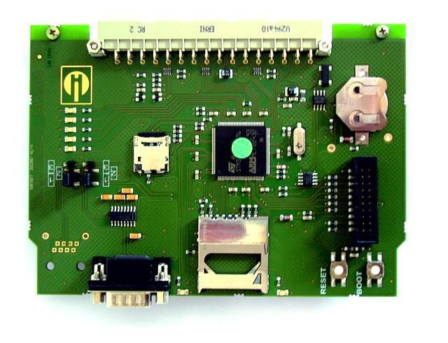
Content

Getting started .................................................................................. 31
Input basic programming data ........................................................ 32
Select operating mode ........................................................................ 32
   Select timing control....................................................................... 32
   Select quantity control ................................................................... 32
   Select quantity control/time priority ................................................ 33
Configure interval (interval pause) ...................................................... 33
Select indicator type and container size ............................................. 34
Calibration ........................................................................................... 34
Select measurement value unit........................................................... 36
Limit value monitoring ......................................................................... 36
   Input operating mode of LV1 and LV2 limit value outputs ............. 36
   Switching functions of the LV1 and LV2 limit value outputs .......... 37
Input purge cycle ................................................................................. 39
Select water meter .............................................................................. 39
BOB operation (operation without constant supervision) ................... 40
Description of the relay outputs .......................................................... 41
   LV1 and LV2 limit value outputs .................................................... 41
   AUX (programmable functional output) ......................................... 42
   Alarm (Fault signal output) ............................................................. 42
Alarm/message – How to proceed when errors occur ........................ 43
Water shortage ................................................................................... 44
Error history......................................................................................... 44
Description of the signal inputs/outputs .............................................. 45
   Stop input ....................................................................................... 45
   External delete (external acknowledge) ........................................ 46
   Input water meter ........................................................................... 46
Current loop 0/4 - 20 mA..................................................................... 46
   Calculation of output currents ........................................................ 47
Serial interface .................................................................................... 48
   Notification format .......................................................................... 48
LCD settings........................................................................................ 49
Description of the SD card functions .................................................. 49
   Storing measurement values ......................................................... 50
   Store error ...................................................................................... 50
   Interim storage for a non-inserted SD card ................................... 51
   Capacity of the SD card ................................................................. 51
   Export basic programming data ..................................................... 51
   Import basic programming data ..................................................... 52
Password protection ........................................................................... 52
   Password input .............................................................................. 52
   Change password .......................................................................... 53
Password protection ........................................................................... 53
Firmware update ................................................................................. 53
   Menu-driven firmware update ........................................................ 53
   Manual firmware update ................................................................ 55
Maintenance........................................................................................ 55
   Configuring the maintenance interval ............................................ 55
   Acknowledge the maintenance ...................................................... 55

                                                                                                       3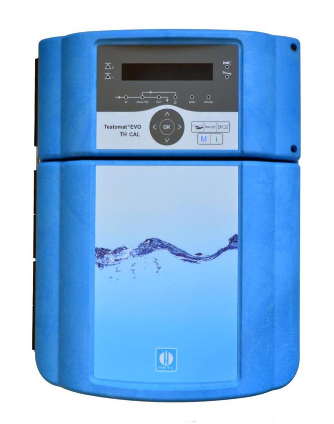
Content

          Information menu "i" ........................................................................ 56
          Service menu ..................................................................................... 57
          Structure of basic programming ..................................................... 59
          Error messages/troubleshooting .................................................... 60
          Further possible errors ........................................................................ 63
          Error messages after self-test ............................................................. 63
          Firmware update error list ................................................................... 65
          Servicing and maintenance ............................................................. 68
          Description of the maintenance work .................................................. 68
             Replacing indicator ........................................................................ 68
             Setting indicator fill level ................................................................ 69
             Cleaning of the measuring chamber and the viewing windows ..... 69
             Cleaning the filter housing ............................................................. 69
          Care instructions ................................................................................. 70
          Replacing the backup battery ............................................................. 70
          Replacing fuses .................................................................................. 71
          Checklist Testomat® EVO TH CAL ..................................................... 75
          Spare parts and accessories for Testomat® EVO TH CAL............ 77
          Accessory............................................................................................ 78
          Technical Data ................................................................................... 79
          Declaration of conformity .................................................................... 80

4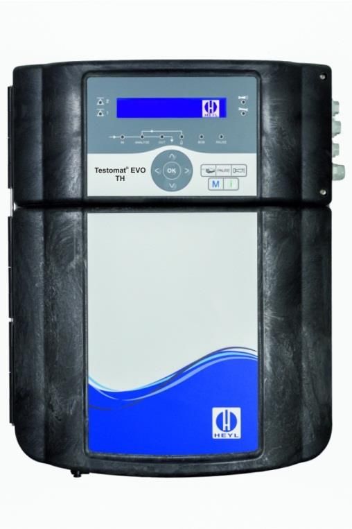
Important safety information

Important safety information
Read the operating instructions carefully and in full before working
with the device.
Ensure that the operating instructions are accessible at any time for
all users. When an SD is used in the device, it can also be stored on
the same as a PDF file.
If transferring the Testomat® EVO TH CAL device to third parties,
ensure these operating instructions are always included.
Observe the safety precautions and safety recommendations when
using reagents, chemicals and cleaning agents. Observe the relevant
safety data sheet! For reagents we supply, the relevant safety data
sheets are available online at http://www.heylanalysis.de.

Intended use
The scope of use of the Testomat® EVO TH CAL is the automatic
determination and monitoring of the residual total hardness (water
hardness) in water. In the process, the required measurement scope
is determined based on the selected indicator and corresponding
user programming.
Thanks to the additional calibration function, the Testomat® EVO TH
CAL can also be used where calibration of the measuring instrument
is important for controlling water quality, e. g. in the pharmaceutical
industry.
Comply with the output limits specified in the "Technical Data" sec-
tion.
Observe the areas/limits of application of the indicators and the re-
quirements imposed by the medium to be measured.
The scope of intended use presumes that you have read and under-
stood the instructions and particularly the section on "Important safety
information".
Improper use is deemed to occur if you use the device
• outside the applicable scope, as specified in these instructions,
• under operating conditions that deviate from the scope specified in
  these instructions.

Qualification of personnel
The assembly and commissioning require basic electrical and pro-
cess engineering expertise as well as knowledge of the applicable
specialist terms. The assembly and commissioning must therefore be
performed only by a specialist or a properly trained person instructed
and supervised by a specialist.
A specialist is a person who can draw on professional training,
knowledge and experience as well as knowledge of applicable provi-
sions to assess work assigned to him/her, detect potential hazards

                                                                          5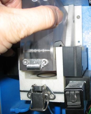
Important safety information

                               and implement suitable safety measures. A specialist must comply
                               with the applicable professional rules.

                               Warnings in this manual
                               These instructions include warnings against specified actions that
                               involve the risk of injury or property damage. Warnings are structured
                               as follows:

                               Description of the type or source of danger
          SIGNAL WORD!         Description of the consequences of non-compliance
                               Hazard prevention indications. Compliance with these hazard preven-
                               tion measures is imperative.

                               The signal word "RISK" refers to a significant danger that represents
     !     DANGER
                               a direct threat and will definitely result in severe injuries or even be
                               fatal if not avoided.
                               The signal word “WARNING" refers to a possible danger that may
     !    WARNING              result in severe injuries or even be fatal if not avoided.
                               The signal word "CAUTION" refers to a potentially dangerous situa-
     !    CAUTION              tion that could result in minor to moderate injuries or property dam-
                               age if not avoided.
                               The signal word "NOTE" refers to important pieces of information. If
          NOTE                 this information is not heeded, it may adversely affect operational
                               procedures.

                               Additional documentation
                               The Testomat® EVO TH CAL device is a system component. Accord-
                               ingly, you should also observe the Testomat® EVO TH CAL mainte-
                               nance manual and the system documentation of the system manu-
                               facturer.

                               Special attention is required at this point
                               General Information
      !    WARNING             • During assembly and commissioning, observe the specific national
                                 and local requirements.
                               • Observe the accident prevention and conservation requirements in
                                 the country of use and at the installation site.
                               • Make no changes or modifications to the device that go beyond the
                                 scope of use specified in these instructions. Doing so will void the
                                 warranty.

                               Requirements for the installation site
                               Ensure that the following conditions are met at the installation site:
                               • Use the device in indoor locations only.
                               • The ambient temperature is between 10 and 40°C.

6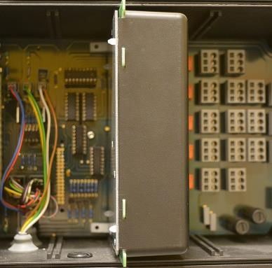
Important safety information

       • The installation site is at altitudes under 2000 m.
       • The maximum relative humidity is 80% at temperatures of up to
         31°C (linear declining up to 50% relative humidity at 40°C).
       • The device must always be protected against wetness and mois-
         ture. Under no circumstances may it be exposed to splashed water
         or condensate.
       • Surge category II
       • Soiling degree II

       Requirements of cable for mains voltage and sys-
       tem components and installed lines
       Use only cables and installed lines which meet the following require-
       ments:
       • Dielectric strength 30 V … 260 V according to the nominal voltage
         (see specification plate)
       • The cable ducts installed by Gebr. Heyl in the device have a
         clamping range of 4.5 mm – 10 mm. This means that the external
         diameter of the laid cable must remain within the range of 4.5 mm
         – 10 mm. If you use other ducts, the cable diameters must corre-
         spond to the ducts.
       • The terminal strips on the circuit board require core cross-sections
         of between 0.08 mm2 and 2.5 mm2. This applies to single-wire and
         fine-wire cores with wire end ferrules without plastic collar.
         For fine-wire cores with wire end ferrules and plastic collar, the
         cross-section may be up to 1.5 mm2.
         For single-wire cores, AWG28 – AWG12 can also be used.

       Optimum cross-section of the cores
NOTE
       If the core cross-section is less than 0.5 mm2, jamming may occur
       when the cores are loosened from the terminal strip. We therefore
       recommend using wires with cross-sections greater than 0.5 mm2.

       Requirements for cable ducts
       • The recesses in the housing are intended for M16 ducts.
       • The ducts should have a smooth and rounded opening (to protect
         against bending and abrasion).
       • Be careful to ensure securely fastened bending protection, which
         must be five times the length of the maximum cable diameter.
       • The duct should include a strain relief that prevents slippage of the
         cable and that cannot be disengaged without a tool.
       • You can order cable ducts from us as spare parts (Spare parts and
         accessories).
         If you use another cable duct, the material must have a flammabil-
         ity rating of V1 or better.

                                                                                 7
Important safety information

                               During assembly
                               • Always disconnect the relevant system component from the power
     !    WARNING                source before assembling the device or connecting it to the power
                                 supply or disconnecting it from the same. Prevent any inadvertent
                                 reactivation of the device.
                               • Only connect the device to the mains voltage as specified on the
                                 type plate.
                               • Observe the technical data and the environmental parameters.
                               • The connections for mains voltage and relay outputs must be laid
                                 separately from each other, to guarantee corresponding insulation
                                 between the cables. Accordingly, do not operate the device if the
                                 partition walls or terminal area covers are not present.

                               Avoiding interference voltages
          NOTE                 The Testomat® EVO TH CAL device requires stable and uninterrupt-
                               ed supply voltage. Where applicable, use a mains filter to shield the
                               Testomat® EVO TH CAL device from interference voltages, which
                               may be generated for example within the network by magnetic valves
                               or large-scale engines. Never lay the connecting cables in parallel to
                               mains cables.

                               Handling may cause damage or destruction of electrical compo-
     !   ATTENTION             nents!
                               If you need to open the upper door, you should take the necessary
                               safety measures to avoid electrostatic discharge onto the compo-
                               nents (ESD safety).
                               Make sure you are earthed before opening the casing.

                               During operation
                               • The device has no power switch.
                                 Use an external power switch to turn the unit on and off. The
                                 switch must be installed next to the device and must be marked as
                                 power switch for the device - for example with a label.
                               • Ensure that the maximum electrical load capacity of the switching
                                 outputs is not exceeded, particularly for inductive loads. The power
                                 supply for the user inclusive device is secured with a 4A fuse,
                                 which means the total of all loads must not reach 4A.
                               • In the event of any malfunctions, immediately switch off the Tes-
                                 tomat® EVO TH CAL device and inform the service personnel.
                                 Never attemt to repair the Testomat® EVO TH CAL device your-
                                 self. Doing do will invalidate the guarantee. Repairs must be per-
                                 formed by authorized service personnel only.

8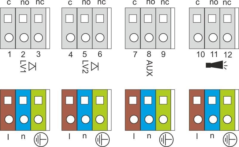
Important safety information

During cleaning
• Only use a dry and lint-free cloth.
• Maintenance and care instructions are included in the section
  "Servicing and maintenance” and in the Testomat® EVO TH CAL
  maintenance manual

Malfunctions/repairing a defective device
• A defective device, regardless of the guarantee period, can be
  serviced only when the device is dismantled and the error is de-
  scribed. Please also inform us of the indicator type currently in use
  and the measured medium. Make no changes or modifications to
  the device that go beyond the scope of use specified in these in-
  structions. Doing so will void the warranty. This applies particularly
  to the measuring chamber, the seal of which must remain undam-
  aged. If you send the device in for repair, please completely empty
  the measuring chamber and remove the indicator bottle and the
  drain funnel. Also remove the power pack and send it back in the
  original packaging.
  Before dismantling, the type of error must be noted (error number,
  error effect, log file of the SD card).
• Once a protective device has been triggered (safety fuse), initially
  try resolving the cause of error (e.g. by replacing a defective
  valve), before reactivating the protective device. Frequent trigger-
  ing always signifies an error, which under certain circumstances
  may also damage the device.
• Before sending the device in for maintenance or repair, pack-
  age the power pack individually in the original box in which it
  was delivered. If the original packaging is no longer available,
  package the power pack to prevent breakage.

During disposal
• Dispose of the device in accordance with the regulations of your
  country.

                                                                         9
Important safety information

                               Operating requirements
                               • Problem-free operation of the Testomat® device is only possible

     !    CAUTION                when using Heyl Testomat indicators and only within the pH range
                                 of 4 – 10.5! Using external indicators may invalidate the guarantee.
                               • Only operate the device within the scope of parameters specified
                                 under "Technical Data".
                               • For Testomat® devices used to monitor water hardness, large
          NOTE                   quantities of heavy metal ions in the hardened water may disturb
                                 the color reaction, particularly
                                   o   Iron over 0.5 mg/I
                                   o   Copper over 0.1 mg/I
                                   o   Aluminum over 0.1 mg/l (brown-red color indication).
                               • If the test water contains more than 20 mg/I CO2 (carbonic acid),
                                 erroneous evaluations cannot be ruled out. In this case, use an ir-
                                 rigator (e.g. optional accessory from Heyl Co.).
                               • The water to be measured must be clean and free of bubbles!
                               • The concentrations of disruptive ingredients can be determined
                                 with colorimetric TESTOVAL® test comparators from Heyl Co.
                               • In the event of
                                   o   excessive carbonate hardness
                                   o   the presence of disinfecting agents
                                   o   the presence of silicate (used to protect pipes), the measur-
                                       ing chamber may become soiled, which over time
                                  may lead to erroneous evaluations
                               • Careful handling of the device enhances the operational safety and
                                 the service life! With this in mind, perform a visual inspection of the
                                 device at regular intervals as follows:
                                   o   Has the expiry date of the indicator elapsed?
                                   o   Are the hose connections of the dosing pump leakproof?
                                   o   Is there any air in the dosing hoses?
                                   o   Are all water connections leakproof?
                                   o   Is the door of the device carefully closed?
                                   o   Is the device excessively soiled?
                                   o   Are the measuring chamber and drain channel/drain hose
                                       clean?
                               • Problem-free operation is contingent on regular maintenance!
                                 Maintenance and care instructions can be found in the "Servicing
                                 and maintenance" section.
                               • Indications of problems can be found in the "Error messag-
                                 es/troubleshooting" section.

10
Delivery includes:
Delivery includes:
1 Testomat® EVO TH CAL
1 plastic bag with:
- Screw cap including hole and an insert for the screw cap of
the indicator bottle
1 package with:
- 1 plastic bag with
• Drain funnel
• 2 screws for mounting power supply unit
- Power supply
1 User manual
Attention!
NOTE Depending on your order, you may have a device with blue or black
housing. The operating instructions apply to both colours, as the
functionality is the same.
Service description
The scope of use of the Testomat® EVO TH CAL is the automatic
determination and monitoring of the residual total hardness (water
hardness) in water. In the process, the required measurement scope
is determined based on the selected indicator and corresponding
user programming.
• Simplified menu-driven operation and programming via backlit
graphic LCD.
• Based on the selected indicator, determinable measurement of
overall hardness (water hardness)
• Free selection of hardness units in °dH, °f, ppm CaCO3, or mmol/l
• Highly accurate measurement thanks to the use of precise piston-
dosing pump
• Extended operating periods due to 500 ml indicator storage bottle
• Analysis trigger:
– Automatic interval operation
(Interval pause can be configured from 0-99 minutes)
– Depending on quantity, via contact water meter
– External disruption of analysis
• Two independent limit values with adjustable switching functions
as well as switching option in accordance with an adjustable num-
ber of negative analyses (Two neutral change-over contacts)
• Logging on SD card for measurement data and notifications/alarms
with interim buffer for 100 measurement values and 50 notifica-
tions.
• Import and Export of settings (basic program data) with selectable
filenames.
11Service description
• Error history for 20 notifications
• Firmware update via SD card
• Built-in self-test with ongoing monitoring
• Optional wireless retrieval of data with special WLAN SD card
• Features for integration into process controllers:
– Fault signal output (neutral changeover contact) with Clear
input
– Current loop 0/4 - 20 mA for analog transfer of measurement
data
– Serial RS232 interface to transfer measurement data and no-
tifications/alarms
Available indicators for Testomat® EVO TH
CAL devices
Parameter/indicator type
Water hardness
TH 2005 TH 2025 TH 2050 TH 2100 TH 2250
°dH 0.05 - 0.50 0.25 - 2.50 0,5 – 5,0 1.0 - 10.0 2.5 - 25.0
(resolution) (0.01) (0.05) (0,1) (0.2) (0.5)
°f 0.09 - 0.89 0.45 - 4.48 0,89 –8,9 1.8 - 17.9 4.5 - 44.8
(resolution) (0.02) (0.1) (0,2) (0.4) (1.0)
Unit
[ppm]
0.89 - 8.93 4.5 - 44.8 8,9 – 89 18 - 179 45 - 448
CaCO3
(0.2) (0.9) (2) (3.8) (10)
(resolution)
mmol/l 0.01 - 0.09 0.04 - 0.45 0,09 –0,89 0.18 - 1.79 0.45 - 4.48
(resolution) (0.01) (0.01) (0,02) (0.04) (0.1)
Please be careful to ensure that Heyl indicators are used!
NOTE Using external indicators may result in considerable measurement
deviations or measurement errors. Damage caused by foreign parti-
cles in the area of the dosing pump, measuring chamber or valves is
also possible. This may invalidate the guarantee!
At Heyl, we always strive to ensure the consistently high quality of
our indicators. They are specially tailored to the requirements of our
measuring devices and guarantee flawless measurement results.
12Assembly
Assembly
Hazard due to defective assembly!
! WARNING
Assemble the Testomat® EVO TH CAL device in a location shield-
ed from drips and splashes of water, dust and aggressive sub-
stances – e.g. in a switching cabinet or on a suitable wall.
Notes for problem-free operating procedures
Assemble the Testomat® EVO TH CAL device vertically and with-
NOTE out mechanical stresses.
Assemble the Testomat® EVO TH CAL device in a location free of
vibration.
Assembling the Testomat® EVO TH CAL
Requirements for the installation site
NOTE
Select an installation site at which the length of the water inlet hose
can be minimized (max. 5 m)
Leave sufficient room on the left side of the device to open the
door.
Drill the mounting holes as specified in the accompanying sketch-
es.
Secure the device with three screws in a suitable place in the
switching cabinet or on the wall.
Use of the Testomat® EVO TH CAL within a
pressure range of 0.3 to 1 bar
Before assembling please check whether adaptation to a lower work-
ing pressure is required. When delivered, the device is equipped for a
Remove for a pressure range of 1 to 8 bar. To operate the device within a pressure
pressure
range of 0.3 range of 0.3 to 1 bar, the flow governor core should be removed
to 1 bar (e.g. when using a type R mini irrigator). For this purpose, take the
locking pin from the controller/filter housing . Then pull the con-
troller plug on the metal brackets out of the drill hole. Then remove
the flow governor core and re-insert the controller plug and locking
pin.
At pressures under 0.3 bar or when sucking out of a tank, our Me-
puClip booster pump can be used.
13Assembly
Connecting the water intake and discharge
!
When using a cooler
CAUTION
Water exceeding 40°C may lead to burns and may damage the
parts of the Testomat® EVO TH CAL exposed to the water.
Notes for problem-free operating procedures
NOTE The water pressure must be within the range 0.3 to 8 bar.
To operate within a pressure range of 0.3 to 1 bar or when supply-
ing via a booster pump, please remove the controller core from the
controller and filter housing. The pump should have a capacity of
25 to 35 liters/hour and be correspondingly resistant to the medium
being measured (e.g. our booster pump MepuClip Art. No. 270410)
For operation exceeding 8 bar, a pressure reducer must be used.
Significant pressure fluctuations should be avoided
The measurement water temperature must be between 10 and
40°C
For water temperatures exceeding 40°C, a cooler must be installed
in the intake of the Testomat® EVO TH CAL.
We recommend short intake lines (under 3m) to the Testomat®
EVO TH CAL. For intake lines longer than 3m, purge periods of
longer than 60s must be configured. For cable lengths exceeding 5
- 10m, we recommend external flushing via the AUX input.
Water intake
The test water is extracted from the sampling pipe and channeled to
the supply nozzles of the Testomat® EVO TH CAL. The device comes
with a plug connection for plastic hoses 6/4 x 1 as standard (external
diameter 6 mm/ internal diameter 4 mm, wall thickness 1 mm).
Connect the linking piece for the intake of the Testomat® EVO TH
CAL directly to the sampling pipe directly behind the water
treatment plant
Always establish the connection vertically upwards, to prevent dirt
particles from being conveyed from the sampling pipe to the device
Assemble a manual stop valve in the intake to the Testomat®
EVO TH CAL
NO !! For the water intake use opaque plastic pressure hose 6/4 x 1
"Sagging"
causes back- (max. length 5 m)
water!
Purge the intake to remove dirt particles
14Assembly
Water drain
The water is conveyed through the measuring chamber via an open
funnel and the drain hose installed on the same and into the duct.
Remove the supplied funnel and accommodate it underneath, in
the recess of the housing designated for that purpose.
Connect the funnel of the Testomat® EVO TH CAL with a drain
hose (internal diameter 12 mm/14 mm)
Lay this hose free of back pressure and without the siphon effect
to the drain
Connect mains and devices
Risk of injury from assembly when voltage present!
! WARNING Unless you disconnect the power supply before commencing assem-
bly, you risk injury, destruction of the product or damage to system
components.
Disconnect all power to the relevant system component before
assembling the Testomat® EVO TH CAL device.
When connecting, use only verified cables with sufficient line
cross-section.
Disconnecting device for the power supply
The unit has no power switch!
Fit the Testomat® EVO TH CAL with a switch as a disconnecting
device for the power supply. Use an appliance switch or a circuit
breaker that meets the requirements of IEC 608947-1 and IEC
60947-3.
The switch must be within easy reach of the user of the Testomat®
EVO TH CAL and clearly marked as a disconnecting device for the
Testomat® EVO TH CAL.
For disconnection, you can also provide a three-pin plug near the
device, which is clearly marked as a disconnecting device for the
Testomat® EVO TH CAL.
Danger of damage due to electromagnetic fields!
NOTE If you assemble the Testomat® EVO TH CAL device or connecting
cables parallel to mains cables or in the vicinity of strong electro-
magnetic fields, the device may be damaged or the measurement
disrupted.
Keep the connecting cables as short as possible
Lay the connecting cables and mains cables separately.
Connect the device with the protective conductor (at 230/100-240
VAC).
Keep interference voltages away from the Testomat® EVO TH CAL
device – e.g. by using a mains filter.
Shield the device from strong electromagnetic fields.
15Assembly
Block diagram of Testomat® EVO TH CAL
Illustrated position of relays: Device without current, mains: 230 V
16Assembly
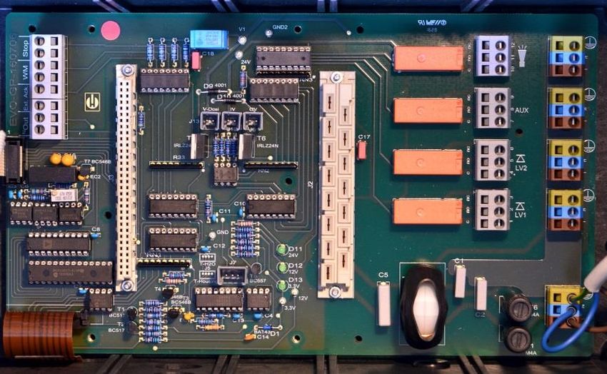
Internal structure of Testomat® EVO TH CAL
Terminal strip for inputs/outputs
Terminal strip for mains inlets and outlets
Terminal strip relay outputs
Dosing pump
Water connections, intake and outlet (funnel)
Controller/filter housing
Measuring chamber
17Assembly
Cable ducting
To guarantee IP protection, the device is supplied with cable ductings
and blanking plugs. If you wish to use a relay output, you must re-
move the blanking plug from the cable ducting.
Proceed as follows in this instance:
Loosen the strain relief of the cable ducting (union nut).
Take out the blanking plug and insert the cable.
Tighten the union nut of the cable ducting and so establish the
strain relief.
Connect mains voltage
Installing the terminal compartment cover
! DANGER
For technical safety reasons, the terminal compartment cover must
be put back in place immediately after connecting the mains voltage
and the system components, since the terminal space houses cables
that carry dangerous voltages. This helps prevent inadvertent contact
with the terminals and contact between the individual lines that may
carry different voltages and thus avoid the risk of a life-threatening
Observe ESD safety
precautions! See the electric shock.
information on page 8 Also ensure that the cables are not pinched when installing the
terminal compartment cover!
Connect the device only to the mains voltage for which it is designed.
See type plate to confirm the suitable mains voltage.
To connect the cable, please proceed as described below:
Remove both fixing screws and open the upper door.
Remove the power supply board from the box at the bottom of the
housing.
Insert the power supply board into the slot on the mainboard.
Screw in the two fastening screws at the top and bottom of the
mainboard.
Remove the fixing screw of the terminal cover and then remove the
terminal cover itself.
Lay the cable through the cable ducting provided for that purpose.
Tighten the union nut of the cable ducting and so establish the
strain relief.
Connect the supply voltage to the terminals PE,N,L or, for 24 V
devices, to U and V terminals.
Ensure that the cores in the terminals are securely in place.
Install the terminal compartment cover.
18Assembly
Terminal designa-
Type Function Note
tion
Mains protective conductor Only for mains supply of
Mass/PE IN
(5x) 230 V and 100 – 240V!
Grid, N=Neutral conductor
N (U) Power input 50-60 Hz
IN (U=24V)
L (V) 24 V / 100-240 V / 230 V
Grid, L=Phase (V=24V)
Neutral conductor, secured
n Grid for consumers, max. 4
OUT with 4A (4x)
l A
Phase, secured with 4A (4x)
Connection example Connect system components
Limit value contact LV 1
switches mains voltage Take out the blanking plugs of the corresponding cable ductings.
Push through the cable of the component.
Tighten the union nut of the cable ducting and so establish the
strain relief.
Connect the system components to the output terminals of relays 1
to 4 (e.g. valves)
If the system components require mains power, connect the exter-
nal switched mains voltage (l) to the root contact of the respec-
tive relay (see accompanying connection example for 230 VAC)
Connect the neutral conductor of the system component with one
of the terminals (n)
For components with a protective conductor connection, connect
them to the PE connection.
Ensure that the cores in the terminals are securely in place
(Illustrated position of relays: Device without current, mains: 230 V)
Indicate external voltage on the relay contacts!
! DANGER If you connect system components that do not operate using the de-
vice voltage, you can apply external voltages to the relay contacts.
This external voltage cannot be switched off via the external mains
switch.
There is a danger of electric shock!
Affix a warning to the device in this case (e.g. a sticker as shown left).
19Assembly
Terminal
No. Type Function Note
designation
1 Limit value output 1 – root c
2 LV1 Limit value output 1 – closing contact Floating relay output,
OUT
3 (limit value) NO max. 240 VAC, 4 A
Limit value output 1 – break contact NC
4 Limit value output 2 – root c
5 LV2 Limit value output 2 – closing contact Floating relay output,
OUT
6 (limit value) NO max. 240 VAC, 4 A
Limit value output 2 – break contact NC
7 Function output – root c
AUX Floating relay output,
8 OUT Function output – closing contact NO
(auxiliaries) max. 240 VAC, 4 A
9 Function output – break contact NC
10 Fault signal output – root c
Floating relay output,
11 Alarm OUT Fault signal output – closing contact NO
max. 240 VAC, 4 A
12 Fault signal output – break contact NC
20Assembly
Connect inputs and outputs
The Testomat® EVO TH CAL device has the following sockets for
control and monitoring functions. Proceed as follows for connection:
Loosen the strain relief of the cable ducting (union nut).
Take out the blanking plugs of the corresponding cable ductings.
Push through the cable of the component.
Tighten the union nut of the cable ducting and so establish the
strain relief.
Re-secure the upper door after installation with both fixing screws.
Correct connection of the inputs and outputs
Do not expose the connections to any external voltage!
! CAUTION
Ensure that the cores in the terminals are securely in place
Incorrect connections will damage the device!
Terminal Typ
No. Function Note
designation e
13 Out +
OUT Current loop 0/4 - 20 mA Galvanically isolated
14 Out -
Ext. Ack. Break contact/closing
contact programmable;
15 (external External reset / acknowledgment input
IN only connect isolated
16 acknowledge port for error and alarms
break contact/closing
) contact
Only connect isolated
17 WM Water meter intake break contact/closing
IN contact or observe the
18 (watermeter) Common ground for inputs technical data of the me-
ter!
19 External disruption of analysis Only connect isolated
20 Stop IN break contacts/closing
Common ground for inputs contacts!
A detailed description is included in "Description of signal in-
puts/outputs".
21Assembly
RS232 interface terminal assignment
1 2 3 4 5
O O O O O
Sub-D 9 poles
O O O O
6 7 8 9
No. Terminal Function
designation
2 RXD Data reception
3 TXD Output of measured values/alarms
5 GND Ground
22Connect indicator bottle
Connect indicator bottle
Flawless operation of the Testomat ® EVO TH CAL device is only
! CAUTION guaranteed when Heyl Testomat 2000® indicators are used! The
use of external indicators may invalidate the guarantee.
Insert indicator bottle
Open the lower housing door by pulling on the right side
Remove the closing cap of the indicator bottle
Remove the plastic bag from the inner side of the lower housing
door. It contains the screw cap with hole and the insert for
the screw cap
Join the parts together as shown below
Screw the hose connector of the suction hose hand-tight into
the insert
Plug the insert with screwed-in suction hose into the indicator bot-
tle
Now screw the screw cap with hole hand-tight onto the indicator
bottle
Open water intake
Open the lower housing lid
Slowly open the manual stop valve to prevent the measuring
chamber from overflowing. Configuring the flow regulator will take
some time during the initial commissioning.
Check the leakproof quality of water-conveying parts
If any water sprays out of the hose of the measuring cham-
ber , restrict the water intake to some extent with the manual
stop valve. The measuring chamber should be filled within two to
six seconds!
Automatic venting
After the device is switched on the indicator lines are automatically
vented and the measuring chamber purged, until indicator is detected
in the measuring chamber. The automatic venting cannot be inter-
rupted. Wait until the venting process has ended and acknowledge
the "voltage failure" error message by pressing the horn key. The
device is then ready for use.
23Functions of the control and display elements
Device settings and data input
Before you configure the required settings and inputs to facilitate
operation of the device, please read the following information.
Functions of the control and dis-
play elements
The operating modes and measurement values are shown on the
display of the Testomat® EVO TH. The input keys for the program-
ming (cursor block) and function keys are underneath the display.
Switching the Testomat® EVO TH CAL device
on/off
(1) External power switch
Use the external power switch to switch the device on or off
(2) Device fuse (internal)
These fuses protect the device or outputs against overload and
short circuit.
Descriptions of the fuses are found in Replacing fuses and under
Spare parts and accessories for the Testomat® EVO TH.
Switching on/off
NOTE
Wait at least five seconds after switching off before switching back
on.
24Functions of the control and display elements
Display functions
All error and warn-
ing messages are
shown in rotation
with the standard
display in line 1!
1 Limit value status indications (red/green)
When the limit values 1 are exceeded, indicator 1 lights up in red.
Falling under the limit value results in the indicator 1 lighting up in
green. The same function applies to limit value 2 and indicator 2.
2 Display
The current analytical result is shown as well as all important
states and programming data
The current measurement value appears on the right
The configured limit values LV1 and LV2 appear on the left. When
the measurement range is exceeded = "" e.g.: > 10.0 °dH
The current analysis interval is suspended (analysis stops) and
the LED "Pause” flashes.
3 LV2 (red/green)
4 LV1 (red/green)
An LED lit up in green indicates that the limit value has been ex-
ceeded.
The LED lit up in red indicates that the limit value has been ex-
ceeded.
5 In (green)
The green LED indicates an opened inlet valve.
6 Analysis message (yellow)
The yellow LED indicates ongoing analysis.
7 Out (green)
The green LED indicates an opened outlet valve.
8 Dosing (yellow)
The yellow LED indicates the activated dosing pump.
9 "BOB operation"
The green LED indicates the activated BOB operation.
25Functions of the control and display elements
10 Pause (green)
The flashing LED indicates the activated pause.
11 Service (yellow)
The yellow LED indicates that the maintenance period has
elapsed.
12 Alarm (red)
Indicates a functional error/error message or warning message.
Handling of error messages/warning messages
NOTE
Eliminate the cause of the error and then acknowledge
the message with the "Horn" button
Control and function keys
Programming
keys
(Cursor block)
Function keys
The “Manual" button (1) is used to start manual anal-
ysis
The "PAUSE" button (2) puts the device into standby
mode (no automatic analysis performed: analysis
stop). However, an ongoing analysis will not be sus-
pended. The device only reverts to pause mode once
the analysis is complete.
Acknowledge error and warning messages with the
“horn" button (3)
The "M" button (4) is used to access the programming
menu for user- and device-specific settings
The "i" button (5) is used to access all device infor-
mation and settings
26Functions of the control and display elements
Input programming data
If you configure settings or wish to input data or when changes are
required, you can call up the programming menu with the "M" button.
Pressing this button in the menu brings you to the higher-level menu
item or you can leave the programming menu.
Programming keys (Cursor block)
The following programming keys (cursor block) are used to navigate
in the menu, select the desired functions and input the required de-
vice- and system-specific data. The "OK" button is used to select the
submenu option and allows the selection or data input to be con-
firmed and adopted.
Indicator of the selected settings
If only one entry from a choice of multiple entries can be selected
from within a menu, a "*" symbol is shown. For all other entries, noth-
ing is shown. Example: Configure indicator
If multiple entries from within a menu can be selected, a " √" is shown,
or “-”, for each of the active settings.
If inputting numbers is possible, the cursor keys are used to
change the position and the buttons to change the value.
Whatever the situation, to be adopted all entries must be confirmed
with "OK".
Operating system
Meaning of the symbols in the menu
In the menu, symbols are shown on the first line at the right-hand
edge. These represent the function keys, which can be used to facili-
tate navigation at this point in the menu.
Symbol Meaning
M/I "M” button, "I” button: Indicates the current
menu (basic program/service or information
Down or up arrows indicate that an additional
selection option is available over or under the
current menu option shown.
Right or left arrows mean that settings can be
viewed with the cursor keys, for example indi-
vidual errors in the error list.
+ A "Plus" means that the selected menu option
includes an additional submenu.
27Functions of the control and display elements
Inputting date and time
PROGRAM MENU
Press the "M" button
The following selection appears: "Basic program" or "Ser-
vice"
Basic program Using the cursor block , select the menu option "Service"
Confirm your selection with "OK"
Using the cursor block select the desired menu option for
Service
"Time Date"
Confirm your selection with "OK"
SERVICE Move the cursor with the buttons to the desired position
Time Date in the time/date field
Select the desired figure by confirming with the cursor keys
Confirm the newly configured values for the time and date with
Time Date
"OK"
Date 05.09.14 If you do not wish to change the values, press no buttons for 30
seconds. The device will then revert back to the values in the op-
erating display.
Press the "M" button to leave the levels.
NOTE The clock continues to run even if the device is switched off.
Selection of functions (Example: "Select operating mode")
Press the "M" button
The following selection appears: "Basic program" or "Ser-
PROGRAM MENU
vice"
Basic program
Confirm "Basic program" with "OK"
Confirm the menu option "Mode of operation" with "OK"
The following selection appears: "Time controlled", "Vol-
BASIC PROGRAM ume interval" or "Volume and Time"
Mode of operation Select the desired function by confirming with the cursor keys
Activate the function with "OK"
(With an active function, an " * " appears at the end of the line)
MODE OF OPERATION This activates the selected function.
Time controlled Press the "M" button to leave the levels.
*
If you have activated one function, the others are automatically deac-
NOTE
tivated.
28Functions of the control and display elements
Inputting of data (Example: interval pause/quantity interval)
Using the menu option "Interval" you can program the interval
pause between two analyses.
To adjust the interval pause, proceed as follows:
Press the "M" button
The following selection appears: "Basic program" or "Ser-
vice"
PROGRAM MENU
Confirm "Basic program" with "OK"
Basic program
Select the menu option using the cursor block
"Interval"
Confirm your selection with "OK"
BASIC PROGRAM The following selection appears: "Time" or "Volume"
Interval
Now confirm the menu option "Time" with "OK"
The cursor flashes on the first digit of the time setting: "◼2"
(You can input values from 0 to 99 minutes)
INTERVAL Confirm with the cursor keys to select the desired digit for
Time ◼2m the first position
Move the cursor with the buttons to the second input field
Confirm with the cursor keys to select the desired digit for
the second position
Now confirm the input with "OK"
The input of the time interval is now complete.
When inputting the quantity interval, proceed when selecting the
menu option "Volume" similarly as to when setting time.
Select the four digits in sequence.
Confirm with "OK".
You can enter values from 1 - 9999 liters.
Press the "M" button to leave the levels.
29Control elements on the control board
• Battery holder : The battery holder houses a CR2032 lithium
battery to retain the time setting even if the device is switched off.
• Plug-in slot for SD card : SD or SDHC cards with a maximum
capacity of 32GByte are suitable. The card must be FAT or FAT32
formatted.
• RESET button : To reset the controller, proceed as for switching
on and off
• BOOT button : Only used when a menu-driven firmware update
is not possible.
• Jumper field : Both jumpers must be plugged into the marked
Position 1. All other positions will render the serial interface unusa-
ble.
Mounting the SD card
Inserting the WLAN SD card
NOTE
If the optional WLAN SD card is used for wireless access, please
observe the operating instructions in the User manual that accompa-
nies the card.
Observe ESD safety
precautions! See the Slide the SD card into the plug-in slot provided, as shown in the
information on page 8 diagram.
Gently press in the SD card until it audibly clicks into place.
The process of mounting the SD card is now complete.
Status displays of the SD card
LED yellow LED red Meaning
On Off Read access on the SD card underway
Off On Writing process underway
SD card error has occurred (also shown
On On
as text alert in the indicator)
LEDs of the SD card
Further information on possible errors is included in the section Error
messages/troubleshooting. How and whether these errors are shown
can be configured in the Alarm/message menu.
30Getting started
Getting started
Once you have completed the steps in the section Connecting indica-
tor, you can switch on the device.
Automatic venting
NOTE After the device is switched on the indicator lines are automatically
vented and the measuring chamber purged, until indicator is detected
in the measuring chamber. The automatic venting cannot be inter-
rupted. Wait until the venting process has ended and acknowledge
the "voltage failure" error message by pressing the horn key. The
device is then ready for use.
You can skip automatic venting by keeping the OK button pressed
when switching on.
Since no settings in the programming menu can be configured while
the analysis is underway, press the PAUSE button once the venting
is complete or proceed to the programming menu before the first
analysis starts!
Now make the following settings, since these are imperative for
obtaining usable measurement values:
- Select Indicator type and container size
- Select display unit of measurement values
Now perform the first measurement by pressing the button. Upon
completion of the analysis, a measurement value must be shown.
If any error occurs, please refer to the section on Error messag-
es/troubleshooting and resolve the error.
Once the first analysis has been successfully completed, you can
adapt the device to your desired usage. The following sections will
set out all the configuration options.
31Input basic programming data
Input basic programming data
Delayed reaction
NOTE
During analysis, the response to any key presses may be delayed.
Select operating mode
Under the menu option "Operating mode" you can select the
type of analytical control. The Testomat® EVO TH CALgives you
scope to control timing or quantity via water meter or a combination
of both.
Smallest pause interval = 0 minutes between analyses. Longest
Timing control
pause = 99 minutes.
Internal trigger by timer. The analysis interval (interval between two analyses) is determined
by the configured purge cycle, the programmed pause time (interval)
and the duration of analysis. The duration of analysis is directly de-
pendent on the measurement value.
Select timing control
Select in the menu => Basic program=> Mode of
MODE OF OPERATION
Time controlled * operation => Time controlled
Volume interval Confirm the selection with "OK"
Volume and Time (An " * " appears at the end of the line)
(The factory default is "Time controlled" " * ")
Now enter the interval.
Select quantity control
Smallest interval = 1 liter, largest interval = 9999 liters. The analysis
Quantity control is performed once the programmed quantity of water has passed.
Triggered by water meter Before the analysis, the line and measuring chamber are purged
(observe programmed purge cycles).
Select in the menu => Basic program => Mode of oper-
ation => Volume interval
Confirm the selection with "OK"
MODE OF OPERATION
(An " * " appears at the end of the line)
Time controlled
Volume interval * Select in the menu => Basic program => Interval =>
Volume and Time Volume
Confirm the selection with "OK"
INTERVAL
Time 10m Input the corresponding flow volume in liters
Volume 03501 Confirm the input with "OK"
Now select the water meter .
32Input basic programming data
Select quantity control/time priority
Quantity control The analysis is performed once the programmed quantity of water
Time priority has passed. An analysis is always prioritized once the programmed
interval pause has elapsed.
MODE OF OPERATION Select the function
Time controlled
Select in the menu => Basic program => Mode of oper-
Volume interval
Volume and Time * ation => Volume and Time
Confirm the selection with "OK"
(An " * " appears at the end of the line)
Select in the menu => Basic program => Interval =>
INTERVAL
Time 10m Time
Volume 03501 Confirm the selection with "OK"
Select the pause time in minutes with the cursor keys.
(The factory default setting is 10 minutes)
Confirm the input with "OK"
Select Volume with the cursor keys
Confirm the selection with "OK"
Input the corresponding flow volume in liters
Confirm the input with "OK"
Configure interval (interval pause)
With time-controlled analysis trigger, the interval between two anal-
yses is determined by the interval pause (plus purge cycle). The
shortest possible interval pause is 0 minutes. Non-stop analyses are
then performed. The largest interval is 99 minutes.
Select in the menu => Basic program => Interval =>
INTERVAL
Time 10m Time
Volume 00001 Select the pause time in minutes with the cursor keys.
(The factory default setting is 10 minutes)
Confirm all entries with "OK"
Duration of the analysis interval
NOTE
The time for the analysis interval comprises the cumulative
time taken for the “Analysis interval", “Purge" and the dura-
tion of analysis, which depends on the measurement value
(see accompanying diagram).
When you perform additional purging via the AUX relay be-
fore or after the analysis, the duration of the analysis interval
will be extended accordingly.
33You can also read