Humpback Whale Encounter with Offshore Wind Mooring Lines and Inter-Array Cables - BOEM
←
→
Page content transcription
If your browser does not render page correctly, please read the page content below

PNNL-27988

Humpback Whale Encounter
with Offshore Wind Mooring
Lines and Inter-Array Cables
Final Report
October 2018
A Copping
M Grear

This report is available from the Bureau of Ocean Energy Management by referencing
OCS Study BOEM 2018-065. The report may be downloaded from BOEM’s Recently
Completed Environmental Studies – Pacific web page at http://www.boem.gov/Pacific-
Completed-Studies/.

PNNL-27988
PNNL-27988

Humpback Whale Encounter with Offshore
Wind Mooring Lines and Inter-Array Cables
Final Report

October 2018

A Copping
M Grear

Prepared for the Bureau of Ocean Energy Management
under an Interagency Agreement with the U.S. Department of Energy
Contract DE-AC05-76RL01830/BOEM Interagency Agreement M17PG00047

OCS Study BOEM 2018-065

Pacific Northwest National Laboratory
Richland, Washington 99352
Summary

Floating offshore wind farms have been proposed in the deep waters off the U.S. west coast and Hawaii to
provide renewable energy to coastal populations. Anchoring floating wind platforms to the seabed
requires multiple mooring lines that pass through the water column from platforms at the surface to the
sea floor. Electrical cables also will be draped in the water column between wind platforms. Concerns
have been raised that large cetaceans might encounter lines from an offshore wind array, potentially
causing harm, including entanglement, to the whales. There are few floating offshore wind arrays
anywhere in the world where this encounter can be tested and no completely appropriate industrial
analogues that can be applied. Understanding this potential risk to whales requires other means of
visualizing the likelihood and mechanisms of encounter. An animation has been developed as a method
for communicating this potential risk. This report provides the information used to create an animation of
humpback whales encountering mooring lines and inter-array cables from a hypothetical floating offshore
wind farm.

                                                   iii
Acronyms and Abbreviations
3D three dimensional
BOEM Bureau of Ocean Energy Management
HMPE High Modulus PolyEthylene (material used for mooring lines)
NREL National Renewable Energy Laboratory
PNNL Pacific Northwest National Laboratory
MW Megawatts
m meters
rpm rotations per minute
s seconds
vContents
Summary ...................................................................................................................................................... iii
Acronyms and Abbreviations ....................................................................................................................... v
1.0 Introduction .......................................................................................................................................... 1
2.0 Literature Review of Humpback Whale Parameters ............................................................................ 2
2.1 Morphometrics ............................................................................................................................. 2
2.2 Behavior ....................................................................................................................................... 3
3.0 Humpback Whale Model ...................................................................................................................... 4
4.0 Floating Wind Farm Parameters and Model ......................................................................................... 5
5.0 Animation Storyline ............................................................................................................................. 6
6.0 Animation and Video Production ......................................................................................................... 7
7.0 References ............................................................................................................................................ 7
Appendix A –– Morphometric Data ......................................................................................................... A.1
Appendix B – Behavioral Data ..................................................................................................................B.1
Appendix C – Wind Array Data ................................................................................................................C.1
Appendix D – Animation Inputs ............................................................................................................... D.1
Figures
Figure 1. Humpback whale model based on literature review dimensions ...................................... 4
Figure 2. Humpback whale model with rigging highlighted in orange. ........................................... 4
Figure 3. Scaled drawing of platforms, moorings and the inter-array array cables around two turbines. ... 5
Tables
Table 1. Averaged morphometric data used for animated encounter scenarios........................................... 3
Table 2. Averaged measurements of adult humpback whale behaviors. ..................................................... 3
vii1.0 Introduction
Floating offshore wind farms have been proposed in the deep waters off the U.S. west coast and Hawaii to
provide renewable energy to coastal populations. Anchoring floating wind platforms to the seabed
requires multiple mooring lines that pass through the water column from platforms at the surface to the
sea floor. Electrical cables will also be draped in the water column between wind platforms. Concerns
have been raised that large cetaceans might encounter lines from an offshore wind array, potentially
causing harm, including entanglement, to the whales from the encounter. There are few floating offshore
wind arrays anywhere in the world where this encounter can be tested, and no completely appropriate
industrial analogues that can be applied. Understanding this potential risk to whales requires other means
of visualizing the likelihood and mechanisms of encounter. An animation has been developed as a method
for communicating this potential risk. This report provides the information used to create the animation of
humpback whales encountering mooring lines and inter-array cables from a hypothetical floating offshore
wind farm.
The Bureau of Ocean Energy Management (BOEM) Pacific Region asked the U.S. Department of Energy
through Pacific Northwest National Laboratory (PNNL), to provide visualizations and input to scenarios
that describe potential encounters of a humpback whale adult-calf pair with mooring lines and inter-array
cables from a floating offshore wind farm. To inform the animation of the humpback whales (Megaptera
novaeangliae) encountering an offshore wind farm, it was necessary to collect data that describe the
physical attributes of the animals and their swimming and diving behavior in the vicinity of a floating
offshore wind farm. A literature review was undertaken to collect whale morphometrics and behavior data
to drive the encounter scenarios between a humpback whale adult-calf pair with an offshore wind farm.
BOEM Pacific staff provided a description and parameters associated with a hypothetical offshore wind
farm.
12.0 Literature Review of Humpback Whale Parameters
The literature review to collect appropriate whale data was conducted using published literature sources
and online databases. While the animation is directed at humpback whale populations off the shores of
California and Hawaii, it was assumed that worldwide population behavior would not differ significantly.
Hence, the literature review was expanded to include morphometric and behavior data from humpbacks
worldwide.
Creating realistic scenarios requires the input of several parameters, loosely described as morphometric
and behavioral. These parameters include body length, pectoral fin length, body width, and fluke length
for adults and for calves (morphometric); humpback behavior while diving, traveling, or foraging for the
adult and for the adult-calf pair (behavioral); and dive depths, lengths, and time between breathing for
adult and adult-calf pair (behavioral).
2.1 Morphometrics
Appendix A details the morphometric data for adult humpbacks and calves. The greatest collection of
morphometric data was gleaned from Woodward et al. (2006) who attempted to create an “average
whale.” Their report amasses data from several species of baleen whales, and provides the most
comprehensive overview of the range of humpback sizes. The average whale is a combination of male
and female measurements (Woodward et al. 2006), for which there is no significant difference in fluke or
flipper dimensions. Winn and Rechiley (1985) reported that females are a bit longer (12.09 m) compared
to males (11.58 m).
The population associated with each set of morphometric data was noted, with a particular focus on the
populations that travel between Alaska and Hawaii and those that travel between California and Costa
Rica or Mexico. Because of the overall small sample sizes, the number of animals measured in each study
was recorded as an approximate measure of data quality.
It is clear from the calf morphometrics that the population of humpbacks off the Hawaiian coast may be
different than those migrating past California. Humpbacks give birth in warm breeding grounds in Hawaii
or Central America (Mexico/Costa Rica); this results in the California coast calves gaining weight over a
longer period of time, which results in slightly larger calves than those born in Hawaii. Because the best
available data are generally from the Hawaii population, the calf measurements used are largely from
neonates. Growth curves from Chittleborough (1965) indicate that three year old humpbacks typically
attain at least 80% of their adult size. Because humpback whales grow quickly and can double in length
during the first year, it was assumed that a calf migrating off the coast of California would be
approximately half the length of the adult.
For the purposes of the animation, BOEM and PNNL determined that the largest cross-section (and
perhaps the most at risk for entangelment) configuration of humpback whales would be an adult female
and calf pair. Using values drawn from the scientific literature, a generic adult female and a generic calf
whale of approximate weaning size were created as input to the animation. The data are summarized in
2Table 1. The full data sets are available in Appendix A: Morphometric Data (Table A.1 through Table
A.6)
3Table 1. Averaged Morphometric Data Used for Animated Encounter Scenarios
Measurement Measurement
(a)
Adult Female Length 13.18 m Calf Length 6.59 m
Adult Female Girth(b) 9.85 m Calf Girth(b) 4.92 m
(c)
Adult Female Fluke Length 4.44 m Calf Fluke Length(c) 2.22 m
(d)
Adult Female Flipper Length 4.06 m Calf Flipper Length(d) 2.03 m
(a) Calculated as half the adult length
(b) Calculated as girth = 0.747 × length, at the axilla.
(c) Calculated as Fluke Span Length = 0.337 × Length.
(d) Calculated as Flipper Length = 0.308 × Length.
2.2 Behavior
The behavioral parameters required for the animation included general observations of behavior, as well
as dive speeds, dive depths, dive times, traveling speeds, and foraging speeds. The behavior of humpback
whales can vary based on many factors, including the social context (i.e., traveling or socializing with a
group or with a calf) and the environmental context (i.e., wind speed or water depth) (Kavanaugh et al.
2017). It should be noted that all diving speeds were associated with adult whale foraging. During
foraging, adult whales have been observed to dive down, rapidly change speed, lunge for prey at a fairly
constant depth, and return to the surface (Goldbogen et al. 2008). Assessing accurate dive times is
challenging because there is a bimodal distribution of times based on the number of breaths each whale
takes at the surface and the type of behavior in which they are engaged (The Marine Mammal Center
2017; Goldbogen et al. 2008). Aggregated dive/foraging times and other parameters are summarized in
Table 2. The detailed behavioral data for adult humpbacks and calves can be found in Appendix B:
Behavioral Data (Table B.1 through Table B.).
Table 2. Averaged Measurements of Adult Humpback Whale Behaviors
Behavior Measurement
Dive Speed 2.0 m/s
Maximum Dive Depth 132 m
Dive Duration 6.34 min
Foraging Speed 2.5 m/s
Traveling Speed 3.81 km/hr
43.0 Humpback Whale Model
A three dimensional (3D) conceptual whale model was created based on the morphometrics collected
from the literature. The whale model was created in the 3D open source modeling software Blender1
using the box modeling technique, as a simple animated shape. Every dimension of the whale, including
the girth or width of the fin, was based on data gathered during the literature review. Pictures and videos
of humpback whales were used to better understand the movement of the whales and to augment the data
collected. Color and texture were then applied to the model to develop a more realistic representation of a
humpback whale (Figure 1).
Figure 1. Humpback Whale Model Based on Literature Review Dimensions
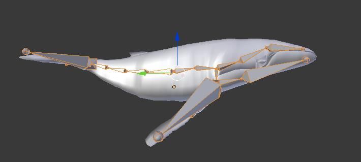
After the simple whale model was created, it was “rigged.” Rigging allows the model to be articulated,
allowing the whale model to bend and distort as a real whale might. The rigging tracks the general
location of the humpback whale model’s spine, allowing caudal oscillation, which constitutes the whale’s
typical swimming mode. Additional articulated “bones” were added to enable the whale mouth to open
and the fins to move (Figure 2). At every node shown in Figure 2, the whale can be moved and rotated,
allowing for different movements and changes in aspect in the animation.
The calf model was created by scaling the full sized (adult) model to one-half size.
Figure 2. Humpback Whale Model with Rigging Highlighted in Orange
1
https://www.blender.org
54.0 Floating Wind Farm Parameters and Model
The description and characteristics for the animated hypothetical floating offshore wind farm were
provided by BOEM, based on an amalgam of information from unsolicited wind energy lease requests, an
existing floating wind installation (i.e., Hywind Scotland Pilot Park), industry input, and design expert
knowledge. The wind farm parameters for the animation were chosen based upon reasonable estimates
and assumptions. The description and characteristics of the wind farm can be found in Appendix C.
Building on the descriptions and characteristics of the floating wind array, an initial representation was
created in AutoCAD. The turbines, floating platform dimensions, depth profile, and cable design were
created from the data provided to PNNL by BOEM. The AutoCAD drawings of the scene can be found in
Appendix C: Wind Array Data (Figures C.1, C.2, and C.3), with overdrawn line thicknesses to highlight
the inter-array cables and mooring lines. Through discussions between BOEM and PNNL, an 8 MW
turbine was chosen for mounting on the floating platform; turbine specifications were fashioned after a
Vestas 8 MW turbine with a 82 m blade length (MHI Vestas 2014). The turbines were configured in a
3 × 3 array (Figure C.3) that could be repeated and scaled to a represent a larger installation.
The AutoCAD drawings were used to inform a 3D scale model of the wind farm created in Blender. The
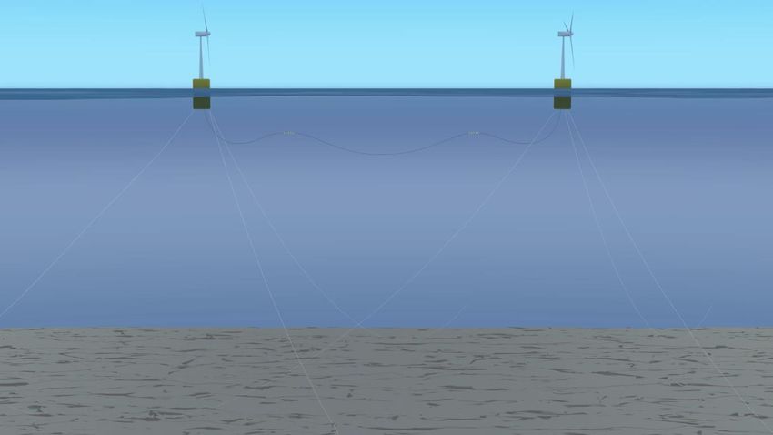
Blender model was animated to create a series of dynamic scenes; an example is shown in Figure 3. A
total of 10 buoys are used to buoy the inter-array cable over the distance of 820 m between platforms; the
floating buoys are 1.6 m in length with a 1.9 m outer diameter.
Figure 3. Scaled Drawing of Turbines, Moorings and the Inter-Array Array Cables Around Two Turbines
65.0 Animation Storyline
A storyline was developed to provide a narrative for the animation of the humpback whale and calf
encountering the wind farm. The storyline is as follows:
If offshore wind farms are installed off the U.S. west coast or Hawaii, migrating humpback whales may
come into contact with these new structures. During this migration, humpback whales are primarily
traveling or foraging. The animation follows a mother and calf pair as they traverse the wind farm
described in Section 3. The video begins by highlighting the whales’ typical migration routes, either
through Hawaii or along the west coast. The layout of the nine turbine array is shown, highlighting the
mooring line placement and inter-array cable design. The mother and calf pair enter the farm and the
mother dives while the calf remains at the surface. During this dive, the mother forages at higher speeds
and travels by the mooring lines, buoys, and inter-array cables.
The animation is approximately three minutes in length, made up of a number of views, including
zooming in on the whales and lines, and views from several angles to demonstrate the scale and layout of
the whales and the wind farm. The swimming speed of the whales and the rotational speeds of the
turbines are presented in real time in all frames. This mix of animation techniques illustrates the whales’
behavior as the mother-calf pair approach, transit, and forage through the the wind farm.
76.0 Animation and Video Production
The 3D animation was produced in Blender using the literature review input parameters and the
animation storyline described in Section 5. Across all scenes, the wind farm parameters provided by
BOEM were used, including the water depth of 700 m. For each scene of the animation, the correct
speeds associated with the movement of the whales was used, based on data retrieved from the scientific
literature; these data are tabulated in Table D.1 in Appendix D, Animation and Video Production Inputs.
Adobe Premeire Pro CC 2018 was used to overlay text on a version of the video to tell the story. The text
for each scene, as well as any additional animations, are shown in Table D.2 in Appendix D.
87.0 References
(Includes sources cited in the appendices)
AW Hawaii Wind LLC. 2015. Hawaii Offshore Wind Energy Lease Application Oahu Northwest.
Retrieved from Bureau of Ocean Energy Management website: https://www.boem.gov/AWH-Northwest-
Project-Lease-App/
AW Hawaii Wind LLC. 2015. Hawaii Offshore Wind Energy Lease Application Oahu South. Retrieved
from Bureau of Ocean Energy Management website: https://www.boem.gov/AWH-South-Project-Lease-
App/
Benjamins S, Harnois, V, Smith, HCM., Johanning, L, Greenhill, L, Carter, C, and Wilson, B. 2014.
Understanding the Potential for Marine Megafauna Entanglement Risk from Renewable Marine Energy
Developments. Scottish Natural Heritage Commissioned Report No. 791.
Cerchio S, Jacobsen JK, and Norris TF. 2001. “Temporal and geographical variation in songs of
humpback whales (Megaptera novaeangliae): Synchronous change in Hawaiian and Mexican breeding
assemblages.” Animal Behaviour 62(2):313–329.
Chittleborough RG. 1965. “Dynamics of two populations of the humpback whale, Megaptera
novaeangliae (Borowski).” Marine and Freshwater Research, 16(1), 33-128.
Dolphin, W.F., 1987. Ventilation and dive patterns of humpback whales, Megaptera novaeangliae, on
their Alaskan feeding grounds. Canadian Journal of Zoology, 65(1), pp.83-90.
Goldbogen JA, Calambokidis J, Croll DA, Harvey JT, Newton KM, Oleson EM, Schorr G, and Shadwick
RE. 2008. “Foraging behavior of humpback whales: kinematic and respiratory patterns suggest a high
cost for a lunge.” Journal of Experimental Biology 211(23):3712–3719.
Herman LM and Antinoja RC. 1977. “Humpback whales in the Hawaiian breeding waters: Population
and pod characteristics.” Sci. Rep. Whales Res. Inst., No. 29, 1977, 59-85.
Holyoake C, Stephens N, and Coughran D. 2012. Collection of Baseline Data on Humpback Whale
(Megaptera novaeangliae) Health and Causes of Mortality for Long-Term Monitoring in Western
Australia. Department of Environment, Western Australia.
Hywind Scotland, Statoil. 2017. Statoil Hywind Scotland Pilot Park Project Plan for Construction
Activities 2017. Retrieved from Marine Scotland Website:
http://marine.gov.scot/sites/default/files/00516548.pdf
Hywind Scotland, Statoil. 2015. Hywind Scotland Pilot Park Environmental Statement. Retrieved from
Marine Scotland Website:
http://marine.gov.scot/datafiles/lot/hywind/Environmental_Statement/Environmental_Statement.pdf
Kavanagh AS, Noad MJ, Blomberg SP, Goldizen AW, Kniest E, Cato DH, and Dunlop RA. 2017.
“Factors driving the variability in diving and movement behavior of migrating humpback whales
(Megaptera novaeangliae): Implications for anthropogenic disturbance studies.”Marine Mammal Science
33(2), 413-439.
9Kniest E, Burns D, and Harrison P. 2010. “Fluke Matcher: A computer-aided matching system for
humpback whale (Megaptera novaeangliae) flukes.” Marine Mammal Science 26(3):744–756.
Mate BR, Gisiner R, and Mobley J. 1998. “Local and migratory movements of Hawaiian humpback
whales tracked by satellite telemetry.” Canadian Journal of Zoology 76(5):863–868.
MHI Vestas Offshore Wind. 2014. V164-8.0 MW® breaks world record for wind energy production.
http://www.mhivestasoffshore.com/v164-8-0-mw-breaks-world-record-for-wind-energy-production/
Noad MJ and Cato DH. 2007. “Swimming speeds of singing and non‐singing humpback whales during
migration.” Marine Mammal Science 23(3), 481–495.
Nolan CP and Liddle GM. 2000. “Measuring sizes of humpback whales (Megaptera novaeangliae) by
underwater videogrammetry.” Marine Mammal Science 16(3):664–676.
Principle Power Inc. 2013. Unsolicited Application For An Outer Continental Shelf Renewable Energy
Commercial Lease. Retrieved from Bureau of Ocean Energy Management website:
https://www.boem.gov/Wind-Float-Lease-Report/
Progression Hawaii Offshore Wind, Inc. 2015. Unsolicited Application for a Section 585 Commercial
Wind Lease on the Outer Continental Shelf Offshore of the South Coast of Oahu. Retrieved from Bureau
of Ocean Energy Management website: https://www.boem.gov/Progression-Hawaii-OCS-Lease-
Application/
Rice DW. 1963. “Progress report on biological studies of the larger Cetacea in the waters off
California.”Norsk hvalfangst-tidende 7:181–187.
Simon M, Johnson M, and Madsen PT. 2012. “Keeping momentum with a mouthful of water: Behavior
and kinematics of humpback whale lunge feeding.” Journal of Experimental Biology 215(21):3786–3798.
The Marine Mammal Center. 2017. “Humpback Whale.” http://www.marinemammalcenter.org/-
education/marine-mammal-information/cetaceans/humpback-whale.html. Accessed: 2017-12-05.
Trident Winds. 2016. Unsolicited Application For An Outer Continental Shelf Renewable Energy
Commercial Lease. Retrieved from Bureau of Ocean Energy Management website:
https://www.boem.gov/MBO-Unsolicited-OCS-Lease-Request/
Winn HE and Reichley NE. 1985. “Humpback whale (Megaptera novaeangliae)”. Handbook of Marine
Mammals.
Witteveen BH, De Robertis A, Guo L, and Wynne KM. 2015. “Using dive behavior and active acoustics
to assess prey use and partitioning by fin and humpback whales near Kodiak Island, Alaska.” Marine
Mammal Science 31(1):255–278.
Woodward BL, Winn JP, and Fish FE. 2006. “Morphological specializations of baleen whales associated
with hydrodynamic performance and ecological niche.” Journal of Morphology 267(11):1284–1294.
Zerbini, AN, Andriolo A, Heide-Jørgensen MP, Pizzorno JL, Maia YG, VanBlaricom GR, DeMaster DP,
Simões-Lopes PC, Moreira S, and Bethlem C. 2006. “Satellite-monitored movements of humpback
whales Megaptera novaeangliae in the Southwest Atlantic Ocean.” Marine Ecology Progress Series
313:295–304.
1011
–
                                       Morphometric Data

A.1 Length
For the length of each animal, measurements were converted to meters and tabulated (Table A.1). Note
that the Woodward et al. (2006) average is taken from many sources. The Marine Mammal Center,
located in Sausalito, California, describes an average length of 15–16 m for Northern Hemisphere
humpbacks, while reporting an average length of 18 m for Southern Hemisphere humpbacks. However,
this information is not cited or reflected in the literature, so was not included in the averages (The Marine
Mammal Center 2017).

                              Table A.1. Length of Adult Humpback Whales
                                             # of Animals                                       Location of
                          Length (m)          Measured            Information Source            Population
 Male                         13.6               —             Herman and Antinoja 1977    Eastern North Pacific
                             11.58               —             Rice 1964                   —
                             11.72               19            Nolan et al. 2000           Hawaii
 Female                      12.09               —             Rice 1964                   —
                              14.8               —             Herman and Antinoja 1977    Eastern North Pacific
                             12.67               26            Nolan et al. 2000           Hawaii
 Both sexes                   13.5               128           Woodward et al. 2006
 “Typical” whale by          12.83
 equal weighted average

For calves, only one measurement was designated as a “calf” as opposed to neonate or newborn (Table
A.2). The main source of these data, Holyoake et al. (2012), collected calf data purely about stranded
animals (Holyoake et al. 2012). When the one “calf” datum point is included with the neonates, there is a
very small difference in the length of male and female calves.

                              Table A.2. Length of Humpback Whale Calves
                          Length                                                             Location of
                           (m)         # of Animals Measured      Information Source         Population
 Male                      4.57                 4              Holyoake et al. 2012            Australia
 Female                    4.58                 4              Holyoake et al. 2012            Australia
 Both sexes                4-5                  —              Herman and Antinoja 1977          —
 “Typical” calf by         4.58
 equal weighted
 average

                                                       A.1
A.1.1 Girth
Girth is described as the maximum body circumference taken at the axilla for the study (Table A.3 and
Table A.4). The maximum girth described by Woodward et al. (2006) is a ratio between the girth and
body length, resulting in a ratio of 0.747. The average maximum width, assuming a circumferential shape,
is then approximately 3.21 m.
Table A.3. Girth of Adult Humpback Whales
Location of
Girth (m) # of Animals Measured Information Source Population
Both sexes 10.08 29 Woodward et al. 2006 —
“Typical” whale by
10.08
equal weighted average
Table A.4. Girth of humpback whale calves.
Girth (m) # of Animals Measured Information Source Location of Population
Female 2.38 2 Holyoake et al. 2012 Australia
A.2 Fluke and Flipper Length
Compared to other baleen whales, humpback whales have large fluke and flipper lengths in relation to
their body lengths (Woodward et al. 2006). The ratios of fluke and flipper lengths to body length is given
in Table A.5.
Table A.5. Fluke and Flipper Length of Adult Humpback Whales. Lengths are given as a ratio of the
fluke or flipper length to body length (i.e., fluke length/body length).
Fluke Span # of Animals Location of
Ratio Measured Information Source Population
0.341 — Woodward et al. 2006 —
Both sexes
0.333 — Kniest et al. 2010 —
“Typical” whale fluke ratio by
0.337
equal weighted average
Flipper Length # of animals Location of
Ratio measured Information Source Population
Both sexes 0.308 — Woodward et al. 2006 —
“Typical” whale flipper ratio
0.308
by equal weighted average
A.2Table A.6. Fluke and Flipper Length of Humpback Whale Calves
# of Animals Location of
Fluke Span Measured Information Source Population
Female 1.19 3 Holyoake et al. 2012 Australia
“Typical” calf fluke ratio by 1.19
equal weighted average
Flipper Length # of Animals Location of
Ratio Measured Information Source Population
Female 1.38 3 Holyoake et al. 2012 Australia
“Typical” calf flipper length 1.38
by equal weighted average
A.3–
Behavioral Data
B.1 Dive Speed
Table B.1. Dive Speed for Adult Humpback Whales. For each entry, a single whale was measured
multiple times.
Dive Speed Location of
(m/s) # of dives measured Information Source Population
Foraging
(descending) 1.7 43 Goldbogen et al. 2008 California
Foraging
(descending) 1.5 15 Goldbogen et al. 2008 California
Foraging (ascending) 1.4 43 Goldbogen et al. 2008 California
Foraging (ascending) 1.4 15 Goldbogen et al. 2008 California
Foraging
(descending) 3.0 10 Simon et al. 2012 Greenland
Foraging
(descending) 2.2 39 Simon et al. 2012 Greenland
Foraging
(descending) 2.2 49 Simon et al. 2012 Greenland
Foraging
(descending) 2.0 35 Simon et al. 2012 Greenland
Foraging
(descending) 2.2 31 Simon et al. 2012 Greenland
Foraging (ascending) 2.3 10 Simon et al. 2012 Greenland
Foraging (ascending) 2.0 39 Simon et al. 2012 Greenland
Foraging (ascending) 2.0 49 Simon et al. 2012 Greenland
Foraging (ascending) 1.8 35 Simon et al. 2012 Greenland
Foraging (ascending) 2.6 31 Simon et al. 2012 Greenland
“Typical” dive speed
by equal weighted
average 2.0
B.1B.2 Dive Depth
Table B.2. Dive Depth for Adult Humpback Whales
Max Dive Depth Location of
(m) # of Animals Measured Information Source Population
Fish Foraging 107 5 Witteveen et al. 2015 Alaska
Zooplankton 127 3 Witteveen et al. 2015 Alaska
Foraging
Foraging 139 1 Goldbogen et al. 2008 California
Foraging 156 1 Goldbogen et al. 2008 California
“Typical” max 132
dive depth by
equal weighted
average
B.3 Dive Duration
Table B.3. Dive Duration for Adult Humpback Whales
Average Dive
Duration # of Animals Location of
(minutes) Measured Information Source Population
Foraging 7.7 1 (43 dives) Goldbogen et al. 2008 California
Foraging 7.9 1 (15 dives) Goldbogen et al. 2008 California
Fish Foraging 6 5 Witteveen et al. 2015 Alaska
Zooplankton 6 3 Witteveen et al. 2015 Alaska
Foraging
Long Dive 4.11 14 (1009 dives) Kavanaugh et al. 2017 Australia
“Typical” dive 6.34
duration by equal
weighted average
B.2B.4 Traveling Speed
Table B.4. Traveling Speed for Adult Humpback Whales
Time and # of Location
Traveling distance Animals With or of
Behavior Speed (km/hr) measured measured without calf Source Population
4800 km over
Migrating 5 1 — Cerchio et al. 2001 —
40 days
670 km over
Migrating 6.25 1 With Mate et al. 1998 Hawaii
4.5 days
1610 km over
Migrating 4.58 1 Without Mate et al. 1998 Hawaii
14.7 days
Local 250 km over
2.5 1 Without Mate et al. 1998 Hawaii
Movements 3.9 days
Local 30 km over
2.5 1 Without Mate et al. 1998 Hawaii
Movements 0.5 days
Local 820 km over
3.33 1 Without Mate et al. 1998 Hawaii
Movements 9.9 days
1860 km over
Migrating 4.58 1 Without Mate et al. 1998 Hawaii
17 days
3640 km over
Migrating 2.63 1 — Zerbini et al. 2006 Brazil
58 days
3720 km over
Migrating 3.83 1 With Zerbini et al. 2006 Brazil
40 days
Singing 2.34 — 57 Without Noad and Cato 2007 Australia
Not Singing 3.58 — 28 With Noad and Cato 2007 Australia
Not Singing 4.17 — 87 Without Noad and Cato 2007 Australia
Migrating 4.3 — 14 — Kavanaugh et al. 2017 Australia
“Typical”
traveling
speed by
3.81
equal
weighted
average
B.5 Foraging Speed
The foraging speed, as opposed to the speed while diving, is described as the maximum velocity when the
whale is lunge-feeding.
Table B.5. Foraging Speed for Adult Humpback Whales
Location of
Lunge Speed (m/s) # of Lunges Measured Source Population
2.7 362 Goldbogen et al. 2008 California
2.3 89 Goldbogen et al. 2008 California
“Typical” foraging speed
2.5
by equal weighted average
B.3–
Wind Array Data
Parameter Data For Visual Justification
Simulation
Units: ft = feet, kg = kilogram, m = meters, mi = mile, mm = millimeter, nm = nautical miles
Other abbreviations: NREL = National Renewable Energy Laboratory
Ocean Conditions
Water depth 700 m/2300 ft Consistent with Pacific Region unsolicited wind energy lease
requests received and Hawaii Call for Information and
Nomination areas.
Floating Platforms
# platforms in 9 Sufficient to demonstrate scale of array and whales.
scalable array unit
Foundation type Generic rectangular Platform is not the focus of the study, so specific actual platform
block type was not chosen.
Foundation 35 m × 35 m Rough mean of the two platform types that have been proposed in
dimensions the Pacific Region.
Foundation draft 48 m / 157 ft Mean of the two platform types that have been proposed in the
Pacific Region.
Scalable array unit Three rows of three Realistic configuration based on unsolicited lease requests and
configuration platforms each NREL expertise.
Spacing between 820 m/2690 ft/0.5 mi Equivalent to 5 rotor diameters for an 8 MW turbine (a realistic
platforms along turbine size to model), feasible spacing for wake effects along the
row row. This is a conservative estimate in that it is likely the
minimum distance between platforms, therefore on the denser side
of array spacing for a whale. This spacing may result in issues of
overlap of mooring lines along the seafloor; however, since the
lines in the water column and not along seafloor are the focus for
this visualization, the overlap issue will not affect the identified
spacing.
Spacing between 1640 m/5380 ft/1 mi Equivalent to 10 rotor diameters for an 8 MW turbine (a realistic
rows turbine size to model). This spacing may result in issues of
overlap of mooring lines along the seafloor; however, since the
lines in the water column and not along seafloor are the focus for
this visualization, the overlap issue will not affect the identified
spacing.
Rotor diameter 82 m/269 ft For a representative 8 MW turbine.
(i.e., blade length)
Tower height (i.e., 194 m/636 ft For a representative 8 MW turbine.
distance from sea
surface to top of
blade pointing
straight up)
Watch circle radius 90 m/295 ft Platform and attached lines/cable will move in a watch circle with
up to a 90 m radius. Mooring lines and cable must have some
slack to allow for this movement.
C.1Parameter Data For Visual Justification
Simulation
Catenary Mooring System
# mooring lines per Three The most commonly estimated number of mooring lines in
platform unsolicited lease requests and number of lines in existing Hywind
installation.
Connection points On platform sides Realistic and conservative estimate in that it requires more
18 m/59 ft below sea mooring line in the water column than if the lines were connected
surface, three at the bottom of the platform (48 m/157 ft depth).
connections spaced
equidistant from
each other
Mooring line 120° between each Unsolicited lease requests and Hywind installation have mooring
configuration line with respect to lines that are equiangular with respect to the seafloor anchor
the seafloor; 45° circle. Though anchor radius is large, the vertical angle of the
from vertical with mooring line in the water column does not change much based on
respect to the water water depth. Most of the mooring line would be lying on the
column seafloor to reduce vertical load on the anchors. Only Hywind
installation has data on the specific vertical angle of mooring lines
coming off the platform (42° from vertical); project plans indicate
that the angle would not be greater than 45° from vertical.
Mooring line 964 m/3163 ft/0.6 mi Assuming a maximum 45° angle of the mooring line from the
length in water platform and no curve in the line, the length of line in the water
column column would be 964 m. This is a conservative estimate as it
means more line in the water column than if the vertical angle
were smaller. Straight lines were assumed for the purpose of
calculating length, but the visualization will reflect the more
realistic catenary curve shape.
Mooring line High modulus Materials based on unsolicited lease requests. Synthetic rope is
material polyethylene more economical than chain, though chain would be used for
(HMPE) rope at stability, to offset some ballast in the platform, and to connect to
platform and in water the anchor.
column, chain near
anchor attachment
Mooring line 112 mm Materials based on unsolicited lease requests. Specs found
diameter through online market research. Estimated that HMPE rope would
be the mooring line material present at typical whale swimming
depths--chain would be used closer to the seabed.
Mooring line mass 8.2 kg/m Materials based on unsolicited lease requests. Specs found
through online market research. Estimated that HMPE rope would
be the mooring line material present at typical whale swimming
depths--chain would be used closer to the seabed.
Inter-Array Cables (excludes offshore substation and export cable to shore)
Cable type 33 kV Typical cable type. See Hywind cable spec sheet for reference
(appended).
Cable "Daisy chain" - Based on NREL expertise and existing Hywind Scotland Pilot
configuration single cable along Park installation.
turbine rows
Connection points Center of bottom of Generic configuration for the purpose of this study.
platform
C.2Parameter Data For Visual Justification
Simulation
Cable depth 100 m/328 ft at Judgment based on depth of fishing activities, design economics
floats, 150 m at (deeper cable = more cable = higher cost), and industry input to
bottom of sag the Bureau of Ocean Energy Management.
Cable length >1114 m/3655 ft Connection point to platform is at 48 m depth. Need 102 m to get
plus additional cable cable down to designated maximum suspension depth, 820 m
for sagging between horizontal to next platform, 102 m up to connection point = 1024
buoyance modules. m of cable, plus 90 m for watch circle (only one watch circle
instead of two because it is unlikely that two platforms would be
pushed in opposite directions) = 1,114 m. Additional cable length
would be needed for sagging between buoyancy modules.
Empirical data on suspended cables are generally lacking, so these
are rough estimates.
Cable diameter 169 mm Based on Hywind Scotland Pilot Park installation.
Cable mass 50.5 kg/m/33.9 lb/ft Based on Hywind Scotland Pilot Park installation.
Cable float system Generic cylindrical Trelleborg renewbles distributed buoyancy modules referenced as
buoyancy module example.
Number of floats 10 Based on industry input to the Bureau of Ocean Energy
along cable Management.. Floats would be placed in two groups along cable.
Largest float in Trelleborg cable float system design tool results
chosen.
Cable float 1.87 m/6.1 ft Based on results.
diameter
Cable float length 1.622 m/5.3 ft Based on Trelleborg cable float system design tool results.
194.0 m
Figure C 1. Depth Profile of One Offshore Wind Platform in 700 m of Water. Turbine size is based on
Vestas website specification of a 8 MW turbine.
C.3A single turbine platform has three cables connected it to the seabed (Figure C.1). Three platforms in
profile are visualized in Figure C.2 to show how the mooring lines are laid out. Each row of three
platforms were offset from the next row by 410 m (Figure C.3).
Figure C 2. Three Platforms in Profile Show How the Mooring Lines Look in a Single Row of Turbines
Figure C 3. Scale Drawing of Wind Farm Array. Light blue circles represent the effective diameter of
the turbine platform based on where the mooring lines are connected to the seabed.
C.4–
Animation and Production Inputs
Table D 1. Speed Input Parameters Used for Each Animated Scene
Clip Number Clip Description Speed Input Parameters
1 California Coast Migration Routes No speed input parameters
Wind turbine rotation: 10 rpm
2 Flythrough of offshore wind farm
Boat Speed: 20 knots
3 Bird’s eye view Wind turbine rotation: 10 rpm
4 Side view of two turbines Wind turbine rotation: 10 rpm
Wind turbine rotation: 10 rpm
5 Mother and calf approaching wind farm
Whale traveling speed: 1.05 m/s
6 Mother begins diving Whale diving speed: 2.5 m/s
7 Mother forages for krill Whale foraging speed: 4.0 m/s
8 Scale during dive No speed input parameters
9 Mother crosses in front of mooring line Whale diving speed: 2.7 m/s
10 Mother crosses in front of buoy and cable Whale diving speed: 2.2 m/s
11 Mother ends dive and return to calf Whale diving speed: 1.4 m/s
Wind turbine rotation: 10 rpm
12 Mother and calf cross wind farm
Whale traveling speed: 1.05 m/s
13 Sunset Wind turbine rotation: 10 rpm
D.1Table D 2. Text Overlay for Each Scene (still under review). Overlayed animation created with Adobe
After Effects also are described.
Clip Clip Text Text 2 Other Animation
Number Description
1 California Each year, humpback whales Some females have Arrows point to regions
Coast Migration travel along the U.S. west coast their calves with where humpbacks
Routes to northern feeding grounds them migrate
2 Flythrough of In the future, these whales may None
offshore wind encounter a new technology:
farm floating wind turbines
3 Bird’s eye view The floating turbine platforms Animation of mooring
would be anchored to the lines from bird’s eye
seabed using mooring lines view
4 Side view of Buoyed cables would connect Mooring lines and inter-
two turbines rows of platforms to transmit array cables are
the electricity generated emphasized
Text Animation:
water depth: 700 m
platform spacing: 820 m
turbine height: 194 m
whale: 13 m
5 Mother and calf We created this animation to None
approaching visualize the scale of the
wind farm humpback mother and calf
swimming through a
hypothetical floating wind farm
6 Mother begins The mother dives to forage None
to dive while her calf stays near the
surface
7 Mother passes The mooring lines would be The electrical cables None
near mooring fairly taut to keep the platform could be suspended
lines from moving around too much more loosely in the
water column using
floats
8 Feed for Krill Humpbacks rarely dive deeper The electrical cable None
than 120 meters to feed here is suspended at
(Dolphin, 1987) 100-150 meters
depth
9 Scale of farm The spacing between platforms, None
mooring lines, and cables is not
expected to restrict whale
movement
10 Mother crosses The mother may encounter the Each float shown None
in front of buoy electrical cables and floats here is almost 2
and cable during her feeding dives meters in diameter
and about 1.6 meters
long
11 Mother ends None
dive and returns
to calf
D.212 Mother and calf When the mother and calf are None
cross wind farm swimming near the surface,
they should not encounter
mooring lines or cables
13 Sunset Learn more at at BOEM Logo, PNNL
https://www.boem.gov/Pacific- Logo
Completed-Studies/
https://tethys.pnnl.gov/humpba
ck-whales-and-floating-
offshore-wind-farm-animation
D.3You can also read


