Improving Aerodynamic Efficiency and Decreasing Drag Coefficient of an F1 in Schools Race Car
←
→
Page content transcription
If your browser does not render page correctly, please read the page content below
Modern Applied Science; Vol. 15, No. 2; 2021
 ISSN 1913-1844 E-ISSN 1913-1852
 Published by Canadian Center of Science and Education

 Improving Aerodynamic Efficiency and Decreasing Drag Coefficient
 of an F1 in Schools Race Car
 Ao Gai1
1
 Deerfield Academy, Massachusetts, United States
Correspondence: Ao Gai, Deerfield Academy, 7 Boyden Lane, Deerfield, MA 01342, United States.

Received: February 6, 2021 Accepted: March 23, 2021 Online Published: March 29, 2021
doi:10.5539/mas.v15n2p73 URL: https://doi.org/10.5539/mas.v15n2p73

Abstract
To improve the aerodynamic efficiency of a Formula One (F1) in Schools race car, the original model of the car
is evaluated and compared with a new design. The ideas behind the new design are supported by research about
aerodynamics. Different potential designs are created with CAD software Fusion 360 and evaluated within CFD
software Solid Edge 2020 with FloEFD. Empirical data shows how specific changes to the structure of race cars
can improve aerodynamic efficiency by decreasing their aerodynamic drag. The experimental data and methods
of this study can provide help and guidance for teenagers participating in the F1 in Schools competition program
to solve the aerodynamic performance problems of racing cars and thereby increase youth interest in STEM
programs, as well as their opportunities to learn about engineering and enter engineering careers.
Keywords: aerodynamics, computational fluid dynamics, drag coefficient, F1 in Schools
1. Introduction
1.1 Background for the Research
Formula One (F1) is one of the oldest, most popular, and most technologically advanced car racing
championships in the world. From each team’s attention to detail, such as the material used or the slightest tweak
of designs, to the engineers’ constant efforts to improve the aerodynamic efficiency and success of their race cars,
F1 is a paradigm for the world’s advancements in the automobile industry.
The challenge of designing and honing a race car to its maximum potential is brought to high school students by
the F1 in Schools competition. F1 in Schools is a STEM challenge organized by Formula One to encourage high
school students around the world to design a small version of an F1 car. The challenge requires the members of
the participating teams to work together and create a race car that is fast and aerodynamically efficient.
This study is concerned with the improvement of an F1 in Schools race car, the same goal as real-life F1 teams
have pursued throughout the sport’s history. Finding the optimized angle and structure of the car’s wing, the
most efficient body shape of the car, and an aerodynamic rear wing are the three most important areas of
improvement for this project.
1.2 Research Trends
An essential aspect of Formula One’s technology is its advancements in aerodynamic innovations and designs.
In 1968, Graham Hill appeared at the Monaco Grand Prix with a modest wing fitted on his Lotus 49B race car.
This is widely considered the start of aerodynamic enhancement and improvement in F1 racing (Jennie, 2014).
From that point on, aerodynamics – specifically, the creation of more negative lift, or downforce, with the
balance of drag – has always been an aspect that F1 teams have focused on and, as such, has prompted
increasingly complex and interesting wing designs on F1 cars.
During the ground effect era of F1 in the late 1970s and early 1980s, different teams across the F1 grid began
exploring and taking advantage of this aerodynamic principle to decrease the drag and increase the downforce
and cornering speed of their race cars (Graham, 2019). This is just one instance of how F1 teams have always
attempted to design the fastest running machines on the grid with various aerodynamic innovations and
improvements. In 2020, researchers Ilya Tolchinsky, Travis Carrigan and Joshua Dawson used CAD to optimize
the front wing of a racing car and concluded that a higher angle of attack at the tip of the wing produces superior
aerodynamic performance (Tolchinsky, Carrigan, & Dawson, 2020). The work of researchers Jurij Iljaž, Leopold
Škerget, Mitja Štrakl and Jure Marn in 2016 showed that the tail of a car has an important relationship with

 73
mas.ccsennet.org Moddern Applied Sccience Vol. 15, No.
 N 2; 2021

maintainiing the downfforce of a carr, and the dow wnforce increeases with thee height of thhe wing and reaches
 r its
maximum m value at ann 8° angle off attack (Iljažž et al., 2016 6). John Shew w and Leah W Wyman comp pleted the
calculatioon and analyssis of the fron
 nt wing with F FLUENT und der three diffeerent conditionns: wing out of ground
effect, wiing in groundd effect, and wing
 w with enddplates in ground effect. Th he results shoowed that the FLUENT
case for tthe wing with endplates in ground effectt achieved an 80% increase in lift while iincreasing its L/D from
6.9 to 9.00 from the case of the wing out of grouund effect and d without endp plates (John & Leah, 2005 5). Ground
effects haave an impact on the design wing of a car, but measures can be taken to reduce the impact.
 n of the front w
Similar too the efforts of F1 teams an
 nd designers, th
 this study focu
 uses on the aerrodynamic im
 mprovements of
 o an F1 in
Schools ccar, based on past
 p research and
 a aerodynam mic principless.
1.3 Purpoose and Signifficance of the Research
For this rresearch projeect, an F1 in Schools
 S race ccar had alread
 dy been design ned by the teaam, Boyden Challenger,
 C
which paarticipated in the 2020 F1 in Schools cchallenge in China.C The foocus of the sttudy is to im mprove the
aerodynaamic efficiency of the race car and ultim mately to reduuce its drag coefficient
 c as much as possible. The
focus on the drag coeffficient is due to its normaliization of the different factors of the carr and environm ment, such
as air dennsity, speed, and
 a car size, making
 m direct comparisons of drag possiible over a wiide range of conditions.
 c
The efforrts to alter thee structure an
 nd design of thhe car are bassed on additio
 onal research into aerodynamics and
how its eefficiency cann be improved. The experiimental data and methods of this studyy can providee help and
guidance for teenagerrs participatin ng in the F1 in Schools competition program to ssolve the aerrodynamic
performanance problems of racing carss and thereby encourage mo ore young peo ople to particippate in the pro
 ogram and
develop ttheir interests in STEM.
2. Methoods and Theories
2.1 Methoods
Literaturee Research: One
 O of the most m importannt aspects off this study is its researchh concerning the basic
principless of aerodynamics as well as potentiaal areas of exploitation of these princciples. While browsing
different articles and papers
 p online,, useful know
 wledge, princip ples, and sugg
 gestions weree categorically
 y recorded
and archhived. The innformation co ollected serveed as the foundation for the altering of the strucctural and
aerodynaamic design off the original race
 r car.
Computaational Fluid Dynamics
 D (CFFD): The Solidd Edge 2020 CFD C computeer software wiith FloEFD wasw used to
digitally aanalyze the aeerodynamic effficiency of thhe race car. New
 N structural alterations off the race car canc be put
into the C CFD softwaree for virtual calculation,
 c aand the resultss of the tests can be evaluuated. To enssure that a
design exxhibits aerodyynamic improv vement and a lowering of the drag coefficient, the C CFD evaluatioons are all
strictly coontrolled. Eacch of the diffferent variablees within the CFD softwaree is set to a sstandard for alla tests so
that the difference beetween the ev valuations moore precisely reflects the effectiveness of different structural
alterationns, avoiding thhe potential fo
 or human or ccomputationall errors. The reason
 r to use CFD is due to o a lack of
access to a wind tunnel, where the actual conditioons can be meaasured and a more m realisticc drag on the car can be
derived. Although thee CFD model may not prooduce the most accurate ev valuation com mpared to thaat of wind
tunnels, it is the most accessible
 a optiion that can accquire the neeeded informatiion.
2.2 Theorries
Lift: Lift is an upwardd force opposiite to weight. For an objecct or a vehiclee to elevate, thhe force of lifft must be
greater thhan that of its
 i weight. Fo or example, a helicopter’ss wings propel fast enouggh to generate lift that
overcomees the weight of the aircraftt itself, leadingg to takeoff (B
 Brian, 2015) (see
 ( Figure 1)).
Drag: Drrag is the forcce that acts to slow an objeect down with a In a sensee, this idea is similar to
 hin fluids or air.
friction ggenerated by contact
 c betweeen different obbjects. Movin
 ng through watter is harder thhan moving th
 hrough air
because w water normallyy generates more
 m drag thann air.

 Figure 1. Force anallysis of aircrafft in air (Brian
 n, 2015)

 74
mas.ccsennet.org Moddern Applied Sccience Vol. 15, No.
 N 2; 2021

Negative Lift: Negativve lift, more commonly
 c knnown as down nforce, is the vertical forcee of lift in thee opposite
direction.. Downforce is
 i an essentiall considerationn for road vehhicles and racce cars. The ggeneration of downforce
 d
on race cars through thheir intended structural
 s desiigns helps the cars achieve more stabilityy and speed when
 w going
around coorners. Howevver, the more a car can gennerate downforrce, the more the car can geenerate drag. Therefore,
 T
the comppromise betw ween these tw wo aerodynam mics components is of grreat consideraation to man ny vehicle
designerss (Bryan, 20011).
Bernoullii’s Equation and Principlee: Bernoulli’ss Equation an nd its deriveed principle aare named affter Swiss
mathemaatician and phyysician Daniell Bernoulli. Thhe equation iss presented below:
 ℎ
 = ℎ (1)
 v: velocity, : fluid
 f density, h: height, g: gravitational
 g force,
 f P: pressuure
This equuation indicatees the conserrvation of thee sum of kineetic, potentiall, and thermaal energy, sho owing the
relationshhip between velocity,
 v presssure, and elevvation. When Bernoulli’s principle is appplied to the wing
 w of an
aircraft orr a vehicle, it suggests that when the veloocity of air is greater on on wing than the other, the
 ne side of the w
pressure mmust be lowerr on that side than the otherr, since the vaariables are invversely propoortional accordding to the
equation. However, thhe gravitationaal force does not play a paart when the principle
 p is appplied in aerodynamics,
since buooyancy effectss are not imp portant. At thee same time, Bernoulli’s principle
 p only applies to flo ow that is
steady annd without disssipation. With h the appropriiate design off wings, such a difference oof pressure caan serve as
the generration of lift onn an aircraft and
 a downforcee on vehicles (James,
 ( King & W. Carlsonn, 2020) (see Figure
 F 2).

 Figure 2. Bernoulli’s
 B prin
 nciple airflow
 w trajectory (T
 The Columbia Electronic Enncyclopedia)
Drag Coeefficient: The drag coefficieent is a numerrical quantity calculated
 c by a particular eq
 equation to rep
 present the
drag exerrted on an obbject in a fluiid environmennt. The drag coefficient iss usually refeerred to as Cd d, and the
equation is the followinng:
 = (2)
 .

 D:
 D drag, A: thee reference area of the object
The referrence area is an important yet arbitraryy factor when calculating th he drag coeffficient. The frontal
 fr and
planform
 m area of vehiicles are usuaally used as tthe reference area for the equation. Seelecting the ap ppropriate
referencee area and cleearly identifyiing it is key for the equattion to producce an unambiiguous drag coefficient
 c
(Nancy, 22015). The drrag coefficiennt, although diimensionless, is a derived number whicch is directly associated
with the aerodynamic efficiency off a vehicle. Siince it normallizes factors such
 s as fluid ddensity, reference area,
and veloccity in individdual vehicles,, the drag coeefficient can produce
 p a direct and univeersal comparisson of the
drag betw
 ween differentt vehicles.
Ground E Effect: The ground effect, different
 d fromm that of aircraaft wings, is an
 n aerodynamiic term used to describe
the creatiion of fast-flowwing and low-pressure air fflow beneath a car in order to reduce draag and create downforce.
 d
A massivve amount off downforce can c be generaated through the t creation of o a ground eeffect with a minimum
amount oof drag creatioon, which is why
 w the idea off the ground effect
 e has been n adopted by rrace car desig
 gners since
its implemmentation in the
 t late 1970s (Seas).

 75
mas.ccsenet.org Modern Applied Science Vol. 15, No. 2; 2021

3. Race Car Design, Analysis, and Results
3.1 Software
A crucial part of the project is the computer software that allows alterations to be made to the design of the
original race car and completes the analysis of the aerodynamics. Here Autodesk Fusion 360 is used, as well as
FloEFD and Solid Edge 2020.
Autodesk Fusion 360 is a computational-aided design (CAD) software developed by Autodesk. It is an easily
understandable and usable software that allows 3D models to be created, shaped, and exported. This CAD
software is the basis of operation for the original structural design of the Boyden Challenger, the F1 in Schools
model race car that this study focuses on.
Solid Edge 2020, with the implementation of FloEFD, can perform CFD analysis on the design of the race car
that is exported from Fusion 360. FloEFD vitally allows the exported race car model to be simulated within a
correct environment with the correct data restrictions. Furthermore, FloEFD records the essential data and 3D
flow behaviors observed from different perspectives.
3.2 Analytical Restrictions
To ensure the validity of the results of any structural design change, there are several important analytical
restrictions that are made constant for every flow analysis. Each analysis is run on one device with the same
hardware and settings. With a constant environment for the different designs, the difference in results can be
accurately evaluated. The constants and restrictions are below.
Table 1. Hardware configuration
Processor Internal Storage System Version CAD Software CFD Software CPU Speed
Intel(R) 8041 MB / Windows 10 Autodesk FloEFD 2592 MHz
Core(TM) 134217727 MB (Version Fusion 360 FES2019.1.0.
i7-9750H CPU 10.0.18363) Build: 4540
@ 2.60GHZ

Table 2. Flow Analysis Conditions-1
 Flow Analysis Coordinate Reference
 Volume Flow Type
 Type System Axis
 X-axis Y-axis Z-axis
 Object Exterior
 -0.4 m ~ -0.2 m ~ 0m~ Laminar and
 (excluding any Default X
 0.8 m 0.2 m 0.25 m Turbulent Flow
 inner space)

Table 3. Flow Analysis Conditions-2
 Fluid Pressure Temperature Speed Others
 X-axis Y-axis Z-axis
 Air 101325.00 Pa 293.20 K Disabled
 25.000 m/s 0 m/s 0 m/s
Note. Others includes: Transient State Analysis, Object Heat Conduction, Rotation, Weight, High Mach Number
Flow, Humidity.
At the same time, FloEFD allows specific results to be derived from flow tests. Three essential data can be
evaluated from every flow test: drag force, lift, and the drag coefficient. While the drag force and lift can be
directly derived from the flow model, the drag coefficient is derived from a manually inserted equation (see
“Drag Coefficient” on pg.4):
 = (3)
 .

 76
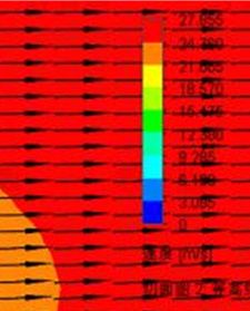
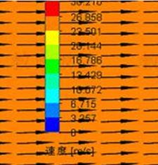
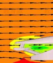
mas.ccsennet.org Moddern Applied Sccience Vol. 15, No.
 N 2; 2021

3.3 First Model Analyssis

 Figure 3. Rendered Orriginal Boydeen Challenger Race Car
The first model of the Boyden Challlenger was deesigned for paarticipation in the F1 in Schhools competition in the
summer oof 2020. Stayying within thee regulations, the race car used the desig gn of a doublle front wing, installing
two covering bodyworrks for the wh heel behind thee required maain wing (see Figure 3). Onne bluff body in front of
another wwould be effective in reduccing the drag of the objectt in the downsstream of the flow. This iss the basic
idea behinnd the design of the bodywwork of the froont wings. Witthout creating g more drag foor the middle part
 p of the
flow overr the body, thhe two bluff bodies
 b in fronnt of the frontt wheels can effectively
 e guuide as much airflow as
possible ppast the frontt wheels, ensu
 uring as little drag as possib ble (Keith & Anatol, 19844). With this design,
 d the
required main wing foor the front wing
 w can stay at a horizonttal angle without an angle of attack, maaking it as
aerodynaamically efficiient as possiblle. The main body shape iss a traditionall streamline ddesign that is often
 o seen
on F1 in Schools race cars. The rearr wing is desiggned to be insstalled on the main body off the car, protrruding at a
90-degreee angle from m the bodywo ork to minim mize interferen nce drag. Twwo converginng bodyworkss are also
designed behind the reear wheels. In addition, the rear of the car has a space in which a CO O2 cartridge is inserted.
The CO22 cartridge is the
 t source of thrust
 t for the car when it iss pierced. How wever, all of tthe tested mod
 dels of the
car do noot involve thee insertion of the cartridgee, since the main
 m goal of th
 he study is too make the caar itself as
aerodynaamically efficient as possible.
 Flow analysis result of the first
Table 4. F f model

 Name Unit Value

 Drag N 0.426

 Lift N 0.020

 Cd 0.493

 Fig
 gure 4. The sidde view of thee airflow velocity
Combininng the resultss with the ob bservation off airflow arou und the car, there
 t are sevveral obvious paths for
reducing the drag (see Figure 4). Firrst, there is an apparent areaa of low-speed
 d air around thhe front wing of the car,
so the opttimization of the front wingg may be helppful for reduciing the drag. Second,
 S there is an area of low-speed
air beneaath the car, whhich indicates a separation of flow and thet creation of a higher-preessure zone beeneath the
car. Finallly, the most apparent
 a issuee is the large w
 wake behind the
 t car, an issue that is knoown to be a major
 m cause

 77
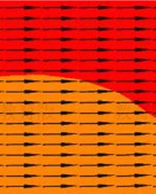
mas.ccsennet.org Moddern Applied Sccience Vol. 15, No.
 N 2; 2021

of drag oon vehicles. Fiixing these issues observedd in the first model
 m of the car
 c are the maain goals for improving
 i
upon the drag coefficieent of the car.
3.4 Frontt Wing Changges
Front winng alteration is the first consideration
 c of structural change for th he race car. A An attempt iss made to
increase the angle of attack for th he forebody oof the front wheel,
 w directinng the airfloww upwards raather than
splitting the air from the middle (S Sun, 2018). T The air that would
 w travel below
 b the forrebody of thee wheel is
observed to be enteringg the space beetween the boddywork and th he wheel, creaating a volum me of separatedd flow and
the assocciated drag wiith the wheel (see Figure 5)). This effect is also reduceed by raising the angle and d lowering
the nose of the foreboddy, since this causes more air to move upwards
 u ratheer than downw wards. The altteration of
the shapee of this structture also does not change thhe frontal reference area of the car, since the structure is directly
in front oof the front whheels, and the area is withinn the wheel.
Figures 5 and 6 and Taables 5 and 6 show
 s the resullts from the front
 f wing alteerations:

 Figure 5.. Front wing aalteration 1 – flow
 f velocity side view

 Figure 6.. Front wing aalteration 2 – flow
 f velocity side view
Table 5. F
 Front wing altteration 1 dataa
 Name Unit Value

 Drag N 0.377

 Lift N 0.014

 Cd 0.437

Table 6. F
 Front wing altteration 2 dataa
 Name Unit Value

 Drag N 0.347

 Lift N 0.020

 Cd 0.402

 78
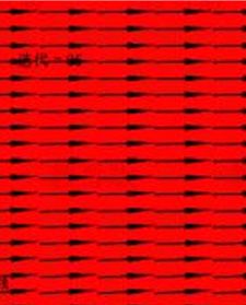
mas.ccsennet.org Moddern Applied Sccience Vol. 15, No.
 N 2; 2021

By obserrving the channge of flow in i the model as well as th he results, it is
 i clear that tthe change off angle of
inclinatioon does decrease the drag exerted
 e on thhe car. While the lift is exp
 pected to decrrease, since raising
 r the
inclinatioon comes withh an expected d increase of ddownforce, th
 he lift did nott need to be aaltered compaared to the
data of thhe original dessign (0.020 N)).
Howeverr, although this version of the front winng proves to be effective in lowering tthe drag of th he car, its
structure has proven to be very sussceptible to daamage, as seen in previous tests. The coonclusions derrived from
this positive change wiill be incorporrated in a morre reliable verssion of the fro
 ont wing.
3.5 Rear Wing Changees
Since dow wnforce is not a necessity for
 f F1 in Schoools race cars due to the sty yle of this racce, the main wing
 w of the
rear wingg is configuredd to zero angle of attack. Thhe original deesign of the reear wing has itt stem directlyy from the
rear of thhe main body of
 o the car, with the original intention of creating
 c a rearr wing withoutut much influen nce on the
drag or ddownforce. Whhile the shapee of the rear w wing remains the same, vorrtex generators rs (VGs) are innstalled in
an attemppt to shrink thhe low-pressurre area that crreates drag at the rear of thee car. The VG Gs are designeed to be of
the heighht of the boundary layer, annd their shapees are of deltaa-wing shape (see( Figure 7)) or of right reectangular
prism shaape (see Figurre 8) (Masaru, Nagayoshi, & Hamahoto, 2004). VGs are a installed oon different loocations of
the rear oof the car besside the CO2 container: thee top, the botttom, and the sides. The reeason for the testing of
different shapes of VG Gs at differen
 nt locations iss to observe any
 a potential improvementt with VGs in n different
areas, widdening the opttions for possible alterationns.

 Figure 7. T
 The delta-wing
 g shape VGs

 Figu
 ure 8. The righht rectangularr prism shape VGs

 79
mas.ccsennet.org Moddern Applied Sccience Vol. 15, No.
 N 2; 2021

 Figure 9. T
 The change off drag force

 Figure 10. The chang
 ge of lift

 Figure
 F 11. Thhe change of drag
 d coefficien
 nt

 Figure 12.
 1 VG installlation version 5 (velocity side view)

 80
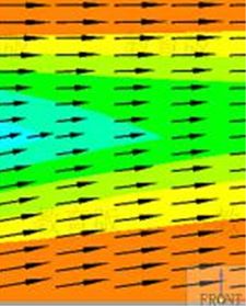
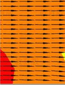
mas.ccsennet.org Moddern Applied Sccience Vol. 15, No.
 N 2; 2021

The side view of the laatest version of
 o the VG insttallation indiccates that the change
 c to the area of vacuu um behind
the car is minimal (seee Figure 12). The
 T results of the tests also indicate very little improveement to the drag d of the
original ccar (see Figurre 11). After analyzing
 a the reason for thee failure behin nd the installaation of VGs, the result
shows thaat the area of the
 t rear of thee car is large eenough for thee wake of the airflow
 a to be oof a certain vo
 olume that
is hard too be altered byy the VGs. Thhe boundary llayer separatees at the sharp p edge no mattter what. Theerefore, an
effective way to reducee the vacuum area is to reduuce the amoun nt of air that can
 c be separateed by shrinkin ng the size
of the reaar of the car.
3.6 Body Change
Several bbody shape changes are also o made to the car in an attem mpt to improvve its aerodynnamic efficienncy (Seas).
Since thee attempt to alter
 a the rear of
 o the car witth vortex generators proved unsuccessfu ful, the alterattion of the
body of tthe car is baseed upon the best
 b version off the car from m the front win
 ng change. Byy observing th he airflow
within prrevious modells, the sidepod m the wake off the front whheels, pushing air below
 d is seen to atttract air from
the car (see Figure 13).

 Figure 13. Orriginal sidepod floor design
 n
Two diffferent reconfiggurations are made to the sidepod and the floor desiign in an effoort to improvee the drag
coefficiennt. The first is to increase the distance bbetween the sidepod
 s and the ground, exxcluding the outer
 o skirt
(see Figuure 14) in ordeer to reduce th
 he pressure benneath the sideepod. The seco ond is the low
 wering of the base
 b of the
car in ordder to reduce the drag with less flow sepparation (see Figure
 F hen, in an atteempt to reduce pressure
 15). Th
drag, the sidepod is alsso altered such
 h that air is noot pushed undeer the bottom of the car (seee Figure 18).

 Figuree 14. Raised sidepod

 81
mas.ccsennet.org Moddern Applied Sccience Vol. 15, No.
 N 2; 2021

 Figurre 15. Lowered
 d floor

 Figure 166. Change of drag
 d force

 Figurre 17. Change of lift

 Figurre 18. Change of Cd

 82
mas.ccsennet.org Moddern Applied Sccience Vol. 15, No.
 N 2; 2021

 Figure
 F 19. Boddy alteration 3—floor
 3 chang
 ge

 Fig
 gure 20. Bodyy alteration 5—
 —sidepod chan
 nge
The bodyy shape changges do not imp prove the aeroodynamics. An ny change to the
 t bottom eleevation of the car or the
sidepod nnegatively imppacts the drag g coefficient oof the car. Thee change of th
 he sidepod shaape of version
 n four (see
Figure 200) proves to bee a failure as well,
 w as the drrag force and its i coefficient spiked alongsside a major increase
 i in
unwantedd downforce. Therefore, th he body shapee of this versiion offers littlle in improvinng the drag coefficient.
Thereforee, a new desiggn is created too overcome thhis plateau.
3.7 Car D
 Design Changge
After the attempted strructural changges to the origiinal race car, a new car is designed
 d to adddress unresolved issues
from passt efforts. Diffferent changess are made to tthe front wingg, rear wing, and
 a body shappe of the car.
The rear wing’s designn is altered by n from the maiin body with tthe purpose of reducing
 y eliminating tthe protrusion
observed pressure dragg in the area, and the mainn wing is thu us connected vertically
 v from
 m the converg ging body
behind thhe rear wheels.
For the ffront wing off the car, the covering boddy in front off the front wh heels does havve the potentiial of rule
violation with its heighht, so the heigght is reducedd in the new design.
 d By increasing the anngle of the slo ope on the
covering body, airflow w can be direected away frrom making direct contactt with the bluuff body of the t wheel.
Howeverr, since the coovering body for f the front w wheels is low
 wered, the airfflow that woul
 uld come from m the main
wing withhout an anglee is predicted to make direcct contact witth the wheels.. Therefore, sseveral possible designs
are testedd with differennt angles of atttack for the m
 main wing, annd the angle beearing the besst result is deeemed to be
optimal. N Notice the anngle of the froont wing in eaach version below
 b (Figure 19, Figure 200, Figure 21). The first
 nd the third veersion has the smallest.
version iss with the greaatest angle, an

 83
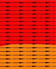
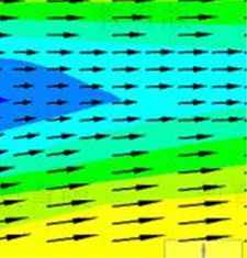
mas.ccsennet.org Moddern Applied Sccience Vol. 15, No.
 N 2; 2021

 Figuree 21. Angle off attack 1 (flow
 w velocity sidee view)

 Figuree 22. Angle off attack 2 (flow
 w velocity sidee view)

 Figuree 23. Angle off attack 3 (flow
 w velocity sidee view)
Table 7. C
 Comparison of
 o results based on differentt angles of attaack

 Angle of attacck 1 Angle of attack 2 Angle of atttack 3

 Name Unit Value Value Value

 Drag N 0.463 0424 0.324

 Lift N -0.090 -0.060 0.028

 Cd 0.612 0.56 0.428

The thirdd result presennts the best datta, with the drrag coefficien
 nt already improved comparred to the firstt model of
the car.
The bodyy shape of thee car is then op
 ptimized usinng the best ressult of the ang
 gle of attack fo
 for the main wing
 w of the
front winng. To reducee the issue of low-speed aiir converging beneath the car c in previouus models, a new body
shape is made to prevvent such an occurrence.
 o A much widerr and taller deesign is madee to reduce th he average

 84
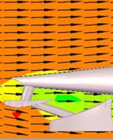
mas.ccsennet.org Moddern Applied Sccience Vol. 15, No.
 N 2; 2021

distance bbetween the car’s
 c floor an
 nd the groundd, and airflow is predicted to flow fasterr around a wiider body,
reducing the change foor slow separation beneath tthe body, whicch was seen in
 n previous moodels.
Additionaally, the sideppod is filled to
 o have its flooor as close to the
 t ground as the skirt is, elliminating any
 y potential
issue seenn before in thhe body chang w inside thee sidepod (seee “The Body Change”).
 ge that would occur if air went
This is also because there is a taller and deeper boody next to it.
 me time, to address the issue of lowerinng the separateed wake regio
At the sam on behind the car, the body
 y is shaped
to converrge as much as a possible within
 w the rulees at the end of
 o the car. Sinnce the body is shaped larrger in the
middle off the car, the converging
 c bo om above andd beneath the car to join
 odywork is prredicted to direct airflow fro
as much as possible toogether behind the car, redducing the reaar vacuum vollume effectiveely. Notice thhe vacuum
volume bbehind the vehhicle in the two
 o new designss.

 Figuree 24. Angle off attack 3 (flow
 w velocity sidee view)

 Figure 25. Body shape alteration 1 (fflow velocity side view)

 Figure 26
 6. Body shape alteration 2 (fflow velocity side view)

 85
mas.ccsenet.org Modern Applied Science Vol. 15, No. 2; 2021

Table 8. Comparison of results based on different body shapes, including the tested results of the third version of
the angle of attack as well as two body shape alterations

 Angle of attack 3 Body shape alteration 1 Body shape alteration 2

 Name Unit Value Value Value

 Drag N 0.324 0.335 0.294

 Lift N 0.028 -0.069 -0.019

 Cd 0.428 0.400 0.351

The second body shape change of the new design aims to resolve the issue of proximity between the bodywork
and the main front wing that appeared to be an area of pressure drag (see Figures 23 and 24). Compared to most
of the side visuals of the tested models, the final two visuals indicate a much smaller volume of vacuum air
behind the car, which is likely to be the reason for the reduction in drag. At the same time, the floor of the
sidepod is as close to the ground as possible, since it is not optimal for air to flow within the sidepod (which it
does in the previous models) if it is open at the front and within.
4. Conclusion
After understanding and applying knowledge from preliminary research concerning aerodynamics, new
structural designs were applied to the initial model of the F1 in Schools race car. While some did not prove to be
effective, others showed major improvements.
The drag coefficient of the final version of the design, under the same circumstances that all versions of the car
were tested, resulted in a drag coefficient of 0.351, which is a 0.142 decrease from the initial value. This result
indicates that the aerodynamic efficiency of the final version of the car is optimized compared to the first.
Certain major design changes proved most helpful. One was finding the optimal angle of attack for the front
wing of the car. Since the front wing is the first part of the car to move through the air, it poses a great source of
drag. Therefore, finding the best shape and angle for the front wing of the car is essential. Another helpful
structural change was streamlining the body shape of the car. While leaving a large open space beneath the car
may appear to increase drag, a larger body that converges at the rear can be more effective, as it prevents flow
separation and higher-pressure air from forming beneath the car, and it reduces the separated zone behind the
car.
F1 in Schools cars have straight line acceleration and straight line deceleration, and this study focuses on
investigating the aerodynamic performance of the car during the steady motion phase. However, in the initial
motion phase with high power, it is also important to explore the performance of the car under the influence of
power. Therefore, considering the dynamic influence would be a useful direction for future research.
References
Dunbar, B. (2015). What Is Aerodynamics? NASA. Retrieved from
 https://www.nasa.gov/audience/forstudents/5-8/features/nasa-knows/what-is-aerodynamics-58.html
Hall, N. (2015). The Drag Coefficient. NASA. Retrieved from
 https://www.grc.nasa.gov/www/k-12/airplane/dragco.html
Iljaž, J., Škerget, L., Štrakl, M., & Marn, J. (2016). Optimization of SAE Formula Rear Wing. Strojniški vestnik -
 Journal of Mechanical Engineering, 62(5), 263-272. https://doi.org/10.5545/sv-jme.2016.3240
John, E. S., & Leah, R. W. (2005). Race Car Front Wing Design. Session: NSC-1: AIAA Foundation National
 Student Conference - Undergraduate Division. (Published Online: 21 Jun 2012)
 https://doi.org/10.2514/6.2005-139
Keilloh, G. (2019). Five Classic Formula 1 Ground Effect Cars. Motor Sport Magazine. Retrieved from
 https://www.motorsportmagazine.com/articles/single-seaters/f1/five-classic-formula-1-ground-effect-cars
Koenig, K., & Roshko, A. (1984). An experimental study of geometrical effects on the drag and flow field of
 two bluff bodies separated by a gap. Journal of Fluid Mechanics, 156, 167-204.
 https://doi.org/10.1017/S002211208500204X

 86
mas.ccsenet.org Modern Applied Science Vol. 15, No. 2; 2021

Koike, M., Tsunehisa N., & Naoki, H. (2004). Research on Aerodynamic Drag Reduction by Vortex Generators.
 Mitsubishi Motors Technical Review.
Mowbray, J. (2014). # F1 History: Aerodynamics in Formula One – Part I. the judge 13. Retrieved from
 https://thejudge13.com/2014/02/05/f1-history-aerodynamics-in-formula-one-part-i/
Prager, J., Karen K., & Denise W. C. (2020). Bernoulli's Principle - Lesson. TeachEngineering.org. University
 of Colorado, September 22, 2020. Retrieved from
 https://www.teachengineering.org/lessons/view/cub_bernoulli_lesson01
Roberts, N. (2019). Understanding Airflow - Knowing a Few Principles of How Air Flows Past a Car Can Help
 You Make Improvements That Really Work. NASA Speed News Magazine. Retrieved from
 https://nasaspeed.news/tech/aero/understanding-airflow-knowing-a-few-principles-of-how-air-flows-past-a-
 car-can-help-you-make-improvements-that-really-work/
Seas. Ground Effect. Formula 1 Dictionary. Retrieved from
 https://www.formula1-dictionary.net/ground_effect.html
Sun, Guoliang. (2018). Racecar Front and Rear Wing Design Based on CFD. University of Qingdao, November
 11, 2018. https://doi.org/10.27262/d.cnki.gqdau.2018.000192
The Columbia Electronic Encyclopedia. Photograph. Bernoulli's Law. Columbia University Press.
 https://doi.org/10.1002/0471743984.vse1032
Tolchinsky, I., Carrigan, T., & Dawson, J. (2020). CAD-Based Optimization of a Race Car Front Wing. SAE Int.
 J. Adv. & Curr. Prac. in Mobility, 2(3), 1422-1428. https://doi.org/10.4271/2020-01-0624
Yager, B. (2001). The Physics of Racing. NASA. NASA, August 27, 2001. Retrieved from
 https://www.nas.nasa.gov/About/Education/Racecar/physics.html

Copyrights
Copyright for this article is retained by the author(s), with first publication rights granted to the journal.
This is an open-access article distributed under the terms and conditions of the Creative Commons Attribution
license (http://creativecommons.org/licenses/by/4.0/).

 87
You can also read