Influence of Different Excavation Sequence of Double-Side Heading Method on Supporting Structure
←
→
Page content transcription
If your browser does not render page correctly, please read the page content below
Hindawi
Advances in Civil Engineering
Volume 2022, Article ID 2258594, 13 pages
https://doi.org/10.1155/2022/2258594

Research Article
Influence of Different Excavation Sequence of Double-Side
Heading Method on Supporting Structure

          Chengkun Ling,1 Yanmei Ruan,2 Pengbo Wu,1 Jin Li,1 Jin Zhao ,3 and Bingxiang Yuan                                         3

          1
            China Railway Tenth Bureau Group Urban Rail Transit Engineering Co.,Ltd., Guangzhou 510000, Guangdong, China
          2
            Guangzhou Metro Design and Research Institute Co., Ltd., Guangzhou 510030, Guangdong, China
          3
            Guangdong University of Technology School of Civil and Transportation Engineering, Guangzhou 510006, Guangdong, China

          Correspondence should be addressed to Bingxiang Yuan; yuanbx@gdut.edu.cn

          Received 23 March 2022; Accepted 5 April 2022; Published 14 April 2022

          Academic Editor: Ping Xiang

          Copyright © 2022 Chengkun Ling et al. This is an open access article distributed under the Creative Commons Attribution
          License, which permits unrestricted use, distribution, and reproduction in any medium, provided the original work is
          properly cited.

          The double-side heading method is often used in the construction of large-span and large-section tunnels. The excavation of the
          pilot tunnel is complex, so the construction efficiency is low. Based on the underground excavation tunnel project of a subway in
          Guangzhou, the section excavation sequence of the traditional double-side heading method is optimized according to the actual
          situation. Midas/GTS software is used for finite element analysis, the displacement and internal force of ground settlement and
          support structure under two different section excavation sequences are calculated, and the calculation results are compared with
          the field monitoring data. The calculation results show that the influence of the two excavation sequences on the displacement of
          the supporting structure is not much different, but the influence on the internal force of the supporting structure is obviously
          different. The stress value of the supporting structure caused by the optimized excavation sequence is larger, especially the
          temporary inverted arch, but it is within the controllable range. The optimized excavation sequence increases the construction
          work surface, greatly improves the construction efficiency, and reduces the project cost, which can provide a reference for the
          construction of urban subway tunnels under similar engineering conditions in the future.

1. Introduction                                                        surface subsidence and surface horizontal displacement
                                                                       [10–12]. For the double-side heading method, many scholars
With the rapid development of urban transportation facil-              at home and abroad had in-depth studies on the safety and
ities, more and more tunnel projects have emerged. Due to              stability of the structure [13–17], soil particle properties
the relatively dense population and buildings on the ground            [18–22], and the deformation law of the surrounding rock
in the city, many underground pipe piles foundations, and              [23–25] in the construction process using the methods of
subway lines, tunnel engineering has high requirements for             field monitoring [26–28], model experiment [29–31], and
construction safety, and any carelessness may result in an             numerical simulation analysis [32–34], but there are few
accident [1, 2]. The construction of an underground tunnel             studies on the optimization of the construction method. Due
will disturb the surrounding buildings (structures), which             to the number of excavation sections, complex construction
will lead to the deformation of buildings, and even threaten           process, high construction cost, and slow construction speed
the life safety of relevant personnel in serious cases [3–5].          of the double-side heading method, it needs to be optimized
Therefore, the deformation and stability control of the                [35]. Zeng [36] optimized the excavation section of the
underground tunnel is the key technical links in urban                 double-side heading method, increased the area of the upper
tunnel engineering [6–9].                                              excavation section, and improved the construction effi-
     Compared with other tunnel excavation methods, the                ciency; Yang et al. [37] optimized the supporting structure of
double-side heading method has advantages in controlling               the tunnel crossing the pebble soil layer, which well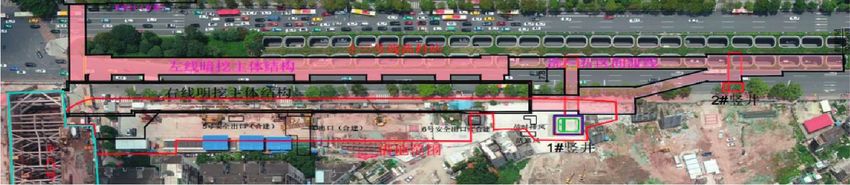
2 Advances in Civil Engineering
controlled the surface settlement and reduced the con- common excavation sequence of sections is that the left and
struction risk; Li et al. [38] optimized the construction step right sections are constructed first and the support system is
of double-side heading method, adopted the excavation formed in time, and then the middle section is constructed,
form of upper and lower sections, reserved core rock pillars namely, ①-④-②-⑤-③-⑥. The optimized excavation se-
in the middle soil layer, accelerated the construction quence of the section is to excavate the upper left and right
progress, and improved the overall stability of the tunnel. pilot tunnels first, then the upper middle pilot tunnel, then
The influence of the construction step on supporting the lower left and right pilot tunnels, and finally the lower
structure has not been discussed in-depth in the above middle pilot tunnel, namely, ①-②-③-④-⑤-⑥.
studies. Based on this, an underground excavation tunnel of
a subway station in Guangzhou is taken as the engineering
background of this article. The tunnel has a large cross-
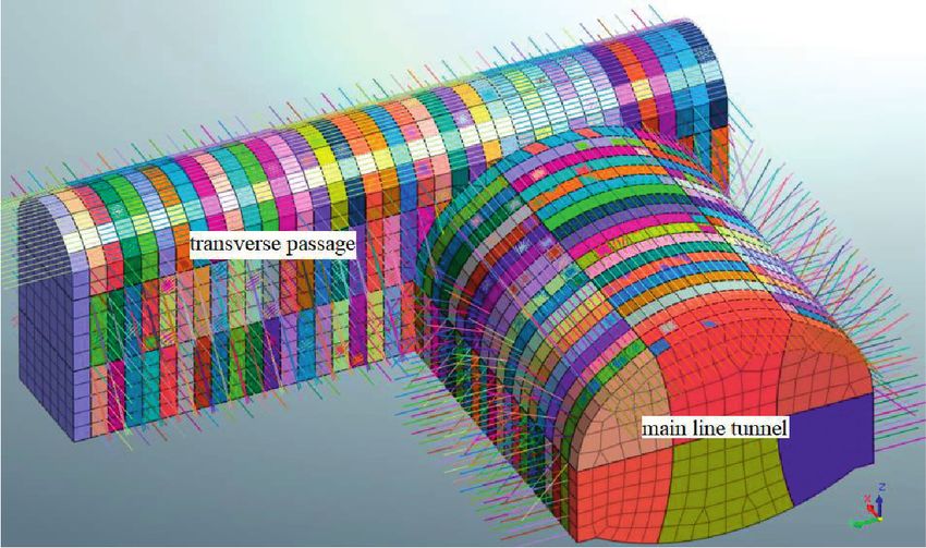
4. Numerical Simulation
section, and there is a large height difference between the 4.1. Calculation Model and Boundary Conditions. The model
lower pilot tunnel of the transverse passage and the upper strata from top to bottom were plain fill, medium coarse
pilot tunnel of the main line tunnel when the construction is sand, plastic residual soil, strongly weathered pelitic silt-
completed. It is difficult to transport workers, machines, and stone, moderately weathered pelitic siltstone, and slightly
materials. Therefore, the excavation sequence has been weathered pelitic siltstone. The model included shaft,
optimized. Midas/GTS software was used for finite element transverse passage, main line tunnel, and foundation pit
analysis. Combined with the field monitoring data, the above the tunnel. According to Saint-Venant’s principle,
displacement and internal force of the supporting structure when the size of the model is 3 to 5 times the tunnel span, the
under different excavation sequences were compared to influence of the boundary effect on the model can be ignored
analyze the safety and stability of the structure. Finally, a [39]. Therefore, the boundary of the overall model was 120 m
reasonable excavation sequence was selected after careful in the X direction, 140 m in the Y direction, and 50 m in the Z
consideration of construction cost, construction period, and direction. The total number of model elements was 130161,
construction safety. The optimized construction scheme not and the total number of mesh nodes was 76573, as shown in
only ensured the safety and stability of tunnel structure but Figure 3.
also greatly improved the construction efficiency, which
provides some reference for tunnels under similar engi-
neering conditions. 4.2. Material Constitutive and Parameters. The
Mohr–Coulomb constitutive model was adopted for plain
2. Engineering Overview fill, medium coarse sand, plastic residual soil, and strongly
weathered pelitic siltstone [40]. The moderately weathered
The underground excavation tunnel interval is located at and slightly weathered pelitic siltstone adopted the modified
about 300 m east of the intersection of West side of Mohr–Coulomb constitutive model because of their rela-
Whampoa Avenue and Xiancun Road, which is connected to tively complete rock structure and hard rock quality. Sup-
the east end of Xiancun Station. Two open-cut shafts were porting structures such as shotcrete, bolt, grid steel frame,
set up, and the rest were underground excavation channel. and section steel adopted the elastic constitutive model. The
The left line is 163.845 m long and goes through the physical and mechanical parameters of each material are
Whampoa Avenue Tunnel in parallel, and the vault is about shown in Table 1.
16.9 m from the bottom of the Whampoa Avenue Tunnel. The initial support of transverse passage and tunnel
The right line is 51.72 m long and is laid below the south side adopted the form of grid steel frame and shotcrete, and the
of Whampoa Avenue, and the vault is about 25 m from the elastic modulus of initial support was calculated by the
ground. The crossover between the left and right lines is method of stiffness equivalence [41]. The equivalent elastic
37.35 m long. The general layout of the underground ex- modulus of initial support was calculated to be 25.382 Gpa,
cavation tunnel interval is shown in Figure 1. and the equivalent elastic modulus of the temporary support
The construction method for the tunnel adopted the was 29.064 Gpa.
double-side heading method. The construction sequence
was to excavate the upper section, construct the supporting
structure, and then excavate the lower section after the
4.3. Simulated Construction Steps. The original construction
construction of the upper section was completed. The daily
scheme and the optimized construction scheme were
footage of construction was 1 m. The finite element model
compared using numerical simulation. The original con-
was modeled and analyzed based on this working condition.
struction scheme was scheme I and the optimized con-
struction scheme was scheme II. The specific construction
3. Construction Optimization Scheme steps of scheme I were as follows (S stands for construction
steps).
The main principle of the double-side heading method is to
divide the large section of the tunnel into small sections (1) Initial stress field analysis (IS): activate the original
using the middle wall, and each small section can be divided strata, gravity, and boundary condition in the nu-
into upper and lower pilot tunnels to avoid stress concen- merical model and cleared the displacement to
tration. The specific section is shown in Figure 2. The simulate the state when the tunnel was not excavated.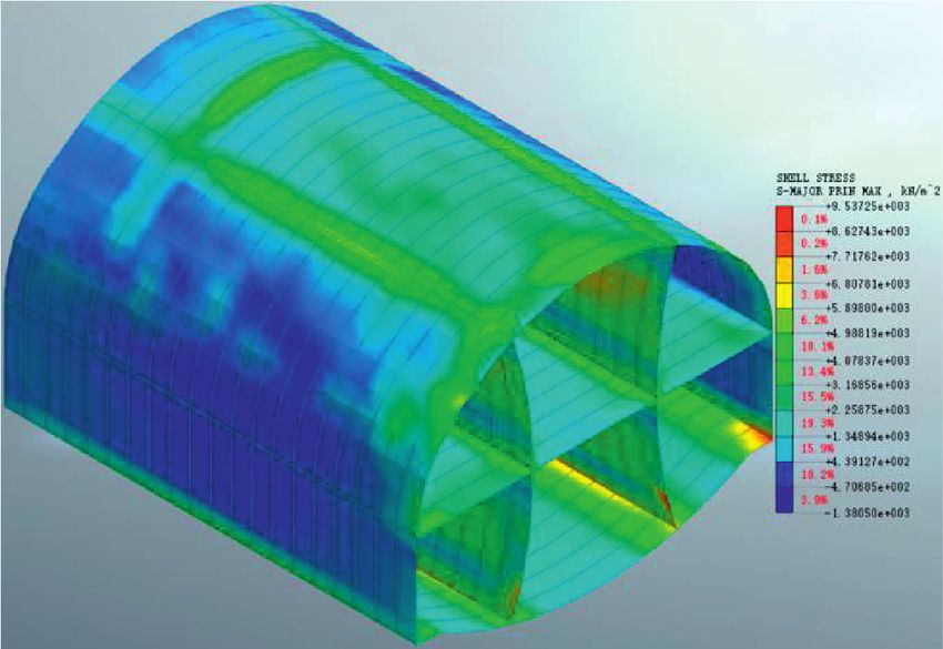
Advances in Civil Engineering                                                                                                    3

                                Figure 1: General layout of underground excavation tunnel interval.

                                                  1             3            2

                                                   4
                                                                              5
                                                                6

                                  Figure 2: Construction process of double-side heading method.

                       (a)                                                              (b)

                    Figure 3: Double-side heading method model. (a) Overall model. (b) Main tunnel model.

   (2) Excavate shaft and foundation pit and construct the                 The specific construction steps of scheme II were as
       supporting structure (S2)                                           follows:
   (3) Excavate the upper (S3–S40), middle (S41–S78), and              (1) Initial stress field analysis (IS): activate the original
       lower (S79–S116) pilot tunnels of transverse passage                strata, gravity, and boundary condition in the
       and construct the supporting structure                              numerical model and clear the displacement to
   (4) Excavate the 1 and 2 (S117), 4 and 5 (S118), 3 (S119),              simulate the state when the tunnel was not
       and 6 pilot tunnels (S120) of the mainline tunnel in                excavated.
       sequence, and the supporting structures of each pilot           (2) Excavate the shaft and foundation pit and construct
       tunnel were constructed after one construction step                 the supporting structure (S2).
       Repeat the above steps until the construction was               (3) Excavate the upper (S3–S40) and middle (S41–S78)
       completed; scheme I included 159 construction steps                 pilot tunnels of transverse passage and construct the
       in total.                                                           supporting structure.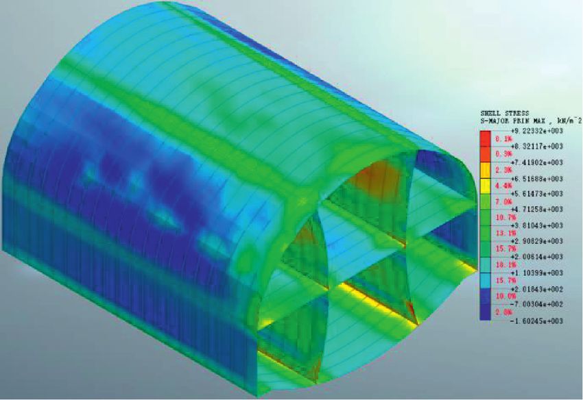
4                                                                                                   Advances in Civil Engineering

                                        Table 1: Physicomechanical parameters of material.
                                       Elastic modulus/    Bulk density/(kN/   Cohesion/     Internal friction angle/   Strata thickness
Material name
                                             (MPa)               m 3)           (kN/m2)                 (°)                   /(m)
Plain fill                                     12.6               19.0             10.0                  9.0                    3.2
Medium-coarse sand                            16.0               20.0              0                   30.0                    2.0
Plastic residual soil                         22.0               22.0             18.6                 18.0                   14.6
Strongly weathered pelitic siltstone          50.0               21.0             45.0                 30.0                   10.0
Moderately weathered pelitic
                                            200.0                25.6            180.0                32.0                    2.2
siltstone
Slightly weathered pelitic siltstone        400.0                26.0            450.0                35.0                   18.0
C25 shotcrete                              23000.0               25.0
Initial support                            25383.0               25.0
Temporary support                          29064.0               25.0
Bolt                                      206000.0               78.5

    (4) Excavate the 1 and 2 (S79) and 3 pilot tunnels (S80)       was a key construction process, and monitoring should be
        of the main line tunnel in sequence, and the sup-          strengthened during on-site construction.
        porting structures of each pilot tunnel were con-              The surface settlement data of the transverse passage at
        structed after one construction step.                      section Y � 70 m in the numerical model was selected for
    (5) Repeat the above steps until the construction of the       comparison and analysis with the field monitoring data. The
        upper section of main line tunnel is completed             on-site construction progress was that the construction of
        (S79–S99).                                                 the upper pilot tunnel of the transverse passage had been
                                                                   completed, and the middle pilot tunnel had been excavated
    (6) Excavate the lower (S100–S137) pilot tunnel of
                                                                   for 6 m. The comparison results are shown in Figure 5.
        transverse passage and construct the supporting
                                                                       Figure 5 shows that the trend of the surface settlement
        structure.
                                                                   results of the transverse passage in the field monitoring data
    (7) Excavat the 4 and 5 tunnels (S138) and 3 pilot             and numerical simulation was basically the same, but the
        tunnels (S80) of main line tunnel in sequence, and         settlement value of field monitoring was larger than the
        the supporting structure of each pilot tunnel were         numerical simulation. The final settlement value of field
        constructed after one construction step;                   monitoring was 13.69 mm, which was 66.6% larger than the
    Repeat the above steps until the construction was              result of the numerical simulation. The reason why the
completed, and scheme II included 159 construction steps in        numerical simulation results were small was that the model
total.                                                             ignored the influence of groundwater [42, 43]. Only self-
                                                                   weight stress was considered in rock and soil mass, and the
                                                                   influence of tectonic stress was ignored. The deformation of
5. Results                                                         rock and soil mass was considered to be isotropic. These
                                                                   simplifications and assumptions made the numerical sim-
5.1. Analysis of Surface Settlement of Transverse Passage.
                                                                   ulation results smaller than the actual settlement value.
After simulation calculation, the surface settlement curve of
the transverse passage with the construction steps as the
abscissa was drawn, as shown in Figure 4, where the                5.2. Displacement Analysis of Initial Support of Tunnel.
monitoring section is Y � 70 m.                                    The displacement value of initial support was extracted
    Figure 4 shows that the final surface settlement of the         according to the monitoring points shown in Figure 6, where
transverse passage is 11.77 mm. The biggest impact on the          the monitoring surface was located at X � 50 m and the
surface settlement of the transverse passage was the exca-         corresponding tunnel excavation distance was 10 m. Figure 7
vation of the upper pilot tunnel of the transverse passage,        shows the displacement diagram of initial support under
and the settlement value was about 8.22 mm, accounting for         different schemes. As can be seen from the figure, the set-
69.8% of the total settlement value. The second was the            tlement value from large to small of the tunnel was vault,
excavation of the upper pilot tunnel of the main line tunnel,      spandrel, hance, and arch foot. The settlement value of the
and the settlement value increased from 9.19 mm to                 right initial support was slightly larger than that of the left
10.99 mm, accounting for 15.3% of the total settlement             because there was a foundation pit above the left initial
value. The excavation of the middle and lower pilot tunnels        support, which reduced the soil press upside, so the set-
of the transverse passage and the lower pilot tunnel of the        tlement of the left initial support was smaller. For scheme I,
main line tunnel had little impact on the surface settlement       when the excavation surface did not reach the monitoring
of the transverse passage. The reason was that the initial         surface, some areas of the monitoring point had slight
support was timely constructed after the excavation of the         displacement. After the excavation reached the monitoring
upper section, which played a role in supporting and lim-          surface, the displacement of the initial support increased
iting the vertical displacement of the soil. Therefore, the        with the advancement of the excavation surface and finally
excavation of the upper pilot tunnel of the transverse passage     tended to be stable.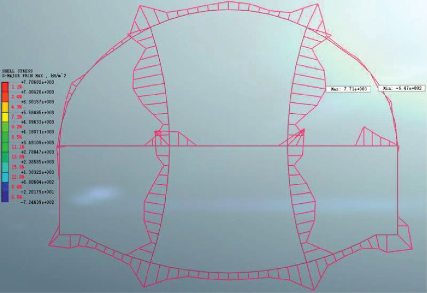
Advances in Civil Engineering                                                                                                                                                   5

                                                                0

                                                               -2

                                       Settlement value (mm)
                                                               -4

                                                               -6

                                                               -8

                                                          -10

                                                          -12

                                                                        0        20        40        60        80        100    120    140    160    180
                                                                                                     Construction sequence
                                                                             Surface settlement of transverse passage
                                       Figure 4: Time-history curve of surface settlement of transverse passage.

                                                               0

                                                               -2

                                                               -4
                            Settlement value (mm)

                                                               -6

                                                               -8

                                                    -10

                                                    -12

                                                    -14

                                                                    0        5        10        15        20        25     30     35     40     45     50
                                                                                                     Construction sequence
                                                                            Field monitoring
                                                                            Numerical simulation
                    Figure 5: Comparison of the time-history curve of surface settlement of transverse passage.

    For scheme II, the influence of tunnel excavation on the                                                         final displacement values of each monitoring point of tunnel
initial support was divided into two parts. The first part was                                                       initial support under different construction schemes are
the excavation of the upper section of the tunnel. At this                                                          shown in Table 2.
time, the vault and spandrel had a large settlement, and the                                                             Table 2 shows that the settlement values of the vault and
settlement of the hance was small. The second part was the                                                          left and right arch feet in scheme II were 4.6%, 77.8%, and
excavation of the lower section of the tunnel, which had a                                                          44.1%, lower than those in scheme I, while the settlement
small impact on the overall initial support. The excavation of                                                      values of the left and right spandrels and hance were 16.4%,
the lower pilot tunnel of the transverse passage had little                                                         17.7%, and 56.1%, 58.9% higher than those in scheme I,
effect on the displacement of the tunnel initial support. The                                                        respectively, and the uplift value of the arch bottom was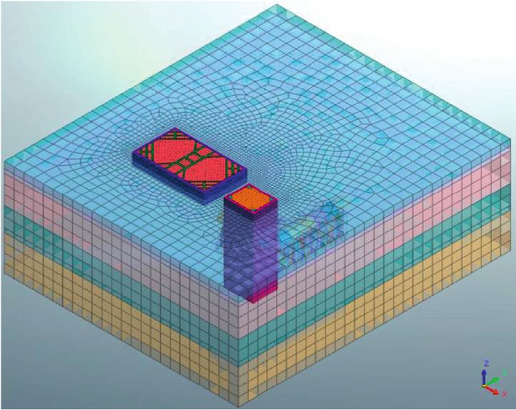
6                                                                                                                                                                                                         Advances in Civil Engineering

                                                                                           Figure 6: Layout diagram of initial support monitoring points.

                                                  2                                                                                                                          2
                                                                                                                           Displacement of initial support of tunnel (mm)
Displacement of initial support of tunnel (mm)

                                                  0                                                                                                                          0

                                                  -2                                                                                                                         -2

                                                  -4                                                                                                                         -4

                                                  -6                                                                                                                         -6

                                                  -8                                                                                                                         -8

                                                 -10                                                                                                                        -10

                                                 -12                                                                                                                        -12

                                                 -14                                                                                                                        -14
                                                       110       120           130           140         150     160                                                              80          100             120           140   160
                                                                              Construction sequence                                                                                                Construction sequence

                                                             Vault                     Right hance                                                                                Vault                   Right hance
                                                             Left spandrel             Left arch foot                                                                             Left spandrel           Left arch foot
                                                             Right spandrel            Right arch foot                                                                            Right spandrel          Right arch foot
                                                             Left hance                Arch bottom                                                                                Left hance              Arch bottom
                                                                                     (a)                                                                                                                (b)

Figure 7: Time-history curves of tunnel initial support displacement under different schemes. (a) Time-history curve of tunnel initial
support displacement in scheme I. (b) Time-history curve of tunnel initial support displacement in scheme II.

3.5% higher than that in scheme I. The displacement values                                                                            sequences of the two construction schemes were different,
of the hance and arch foot of the two construction schemes                                                                            so the stress conditions of the hance and arch foot were
were quite different. The reason was that scheme I was to                                                                              quite different, and the final settlement value was also quite
excavate the sections on both sides first and then excavate                                                                            different.
the middle section after the initial support on both sides                                                                                To sum up, the displacement law of initial support
forms a closed loop; scheme II was to excavate the upper                                                                              caused by different excavation sequences was roughly the
section first and then excavate the lower section after the                                                                            same. Scheme II had a slightly greater impact on the dis-
upper section was completed. The support construction                                                                                 placement of initial support, but within the controllable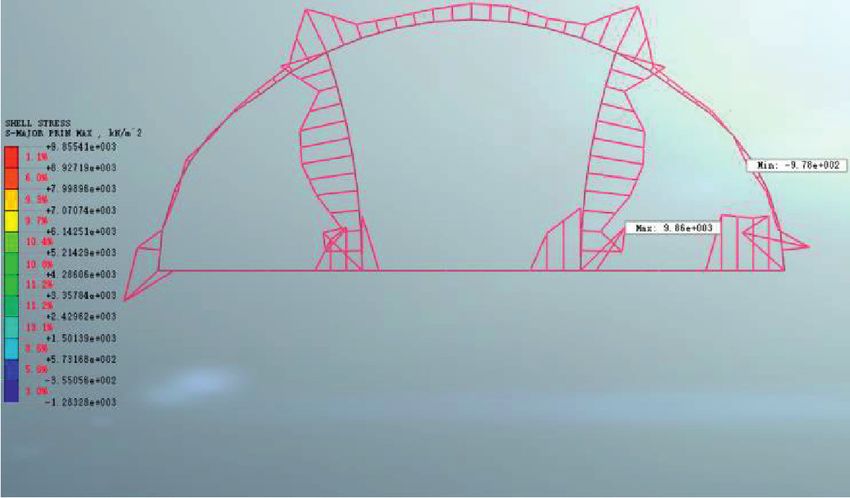
Advances in Civil Engineering                                                                                                  7

Table 2: Final displacement value of monitoring points in initial   monitoring surface, the stress value of the initial support
support of tunnel unit: mm.                                         basically remained stable.
Scheme     ①        ②      ③      ④      ⑤      ⑥      ⑦     ⑧          The time-history curves of the initial support stress of
                                                                    the 1-pilot tunnel of two schemes were compared. Since
I         −13.4    −6.1   −6.8   −2.0   −2.4   −0.6   −0.9   1.4
II        −12.8    −7.0   −8.0   −3.1   −3.8   −0.4   −0.6   1.5    the excavation of the lower pilot tunnel of the transverse
                                                                    passage had little effect on the stress value of the initial
                                                                    support, this part of the data was discarded during the
range. The excavation of 3-pilot tunnel was a key con-              comparison, and the construction steps were reordered.
struction process, so it needed to do well in advance support       The comparison of the time-history curve of the initial
and timely constructed initial support to control the vertical      support stress of the 1-pilot tunnel in the two schemes is
displacement. The excavation of the lower pilot tunnel of the       shown in Figure 10(b). It could be seen that the variation
transverse passage had little effect on the completed tunnel         law of stress value of the initial support of the two
support.                                                            construction schemes was basically the same. The stress
                                                                    values of each monitoring point of tunnel initial support
                                                                    under different construction schemes are shown in
5.3. Stress Analysis of Tunnel Supporting Structure.                Table 3. As can be seen from the table, the maximum
Figure 8 shows the cloud diagram of the major principle             tensile stress of scheme II was 7.7% higher than that of
stress of supporting structure when the tunnel excavation of        scheme I, and the maximum compressive stress was 240%
different schemes was completed. As seen from the figure,             higher than that of scheme I. Therefore, the first con-
the major principal stress distribution and value of the            struction of the supporting structure on both sides could
tunnel supporting structure of the two schemes were basi-           timely distribute the surrounding rock pressure to the
cally the same. In terms of initial support, most of the            lower support, reduced the stress value on the initial
spandrel and hance were compressed, and a small part was            support, and was more conducive to the safety of the
tensioned at the front of the tunnel. Most of the vault and         structure.
arch bottom were compressed, and a small part was ten-
sioned at the end of the tunnel. In terms of temporary              5.3.2. Temporary Inverted Arch of 1-Pilot Tunnel. The stress
support, most of the temporary inverted arch and the middle         value of the temporary inverted arch was extracted
wall were tensioned; the part of the temporary inverted arch        according to the monitoring points shown in Figure 9. As
near both ends of the tunnel and the middle wall near the           can be seen from Figure 11, the stress value of the tem-
temporary inverted arch would be compressed. The stress             porary inverted arch of the 1-pilot tunnel in scheme I
value of the middle wall of the tunnel was greater than that of     increased rapidly during early excavation and then de-
the temporary inverted arch, and the stress value of the            creased slowly with tunnel excavation. The stress value of
upper middle wall was greater than that of the lower middle         the temporary inverted arch of the 1-pilot tunnel in scheme
wall.                                                               II increased continuously when excavating the upper
                                                                    section of the tunnel and reached the peak when excavating
                                                                    the end of the upper section. Then, the excavation of the
5.3.1. Initial Support of 1-Pilot Tunnel. The stress value of
                                                                    lower section of the tunnel would rapidly reduce the stress
initial support was extracted according to the monitoring
                                                                    value of the temporary inverted arch and continue to
points shown in Figure 9, where the monitoring surface was
                                                                    decrease with the excavation. As shown in Table 3, the
located at X � 45 m, and the corresponding tunnel excava-
                                                                    maximum stress value and the stress value at the com-
tion distance was 5 m. As seen in Figure 8, the stress value of
                                                                    pletion of tunnel excavation of the temporary inverted arch
the initial support was symmetrical, so only the left initial
                                                                    in scheme II were 173% and 101% higher than those in
support was selected for analysis.
                                                                    scheme I, respectively. The stress value of the temporary
    Figure 10(a) shows the time-history curve of initial
                                                                    inverted arch in scheme I would be much less than that in
support stress of the 1-pilot tunnel in scheme II. As seen
                                                                    scheme II because the supporting structure on both sides
from the figure, the stress value of the initial support of the 1-
                                                                    was excavated first. The stress value of the temporary
pilot tunnel decreased with the excavation of the upper
                                                                    inverted arch in scheme I would be much less than that in
section, and the stress value changed from positive to
                                                                    scheme II because the supporting structure on both sides
negative when the excavation reached the end of the upper
                                                                    was excavated first, and the stress system of the closed space
section. Then, the lower pilot tunnel, different from the
                                                                    could be formed more quickly.
transverse passage, was excavated, and the excavation on the
side close to the tunnel would slightly increase the com-
pressive stress of the initial support. After the excavation        5.3.3. Middle Wall of 1-Pilot Tunnel. As can be seen from
surface passed through the tunnel surface, the stress value of      Figure 12, the overall trend of the stress value of the
the initial support remained stable. Finally, the lower section     middle wall in 1-pilot tunnel of the two schemes in-
of the tunnel was excavated. When the excavation surface            creased first and then decreased slowly. The difference
had not reached the monitoring surface, the compressive             was that scheme II would cause disturbance to the middle
stress value of the initial support increased with the section      wall when excavating the upper and lower sections, re-
excavation. After the excavation surface passed through the         spectively, and the stress value had two fluctuation points.
8                                                                                                   Advances in Civil Engineering

                                                                 (a)

                                                                 (b)

Figure 8: Different schemes of tunnel supporting structure major principle stress cloud diagram. (a) Tunnel supporting structure major
principle stress cloud diagram of scheme I. (b) Tunnel supporting structure major principle stress cloud diagram of scheme II.

                             Figure 9: The stress value monitoring point layout of supporting structure.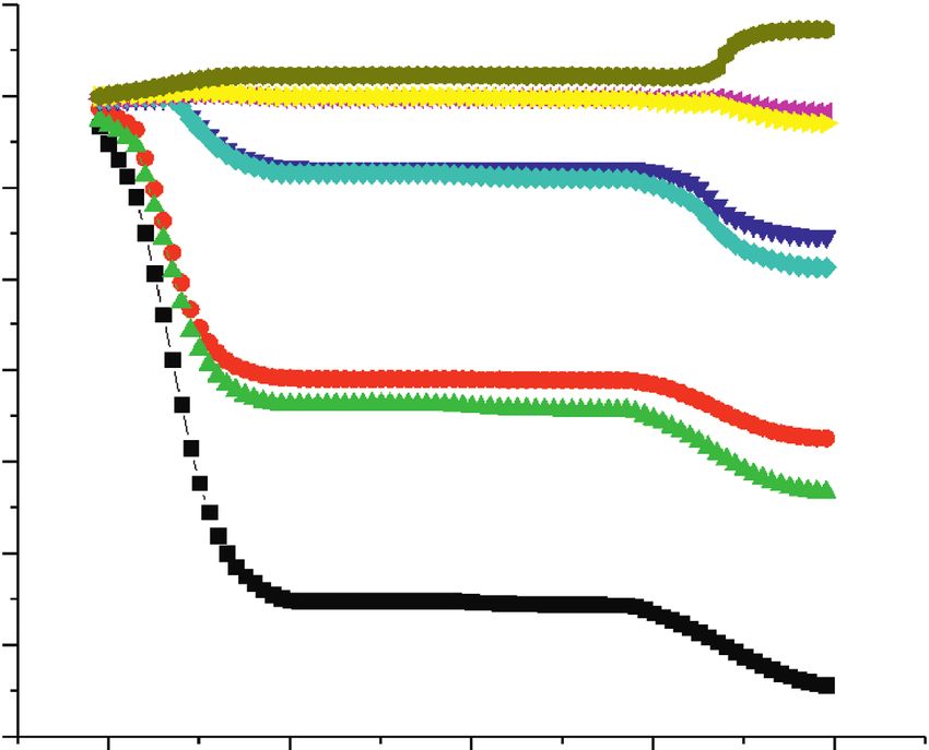
Advances in Civil Engineering                                                                                                                                  9

                                                                                     500

                                                                                     400

                                  Initial support stress of 1-pilot tunnel (kPa)
                                                                                     300

                                                                                     200

                                                                                     100

                                                                                       0

                                                                                     -100

                                                                                     -200

                                                                                            80       90      100      110      120   130    140   150    160
                                                                                                                    Construction sequence
                                                                                                 Scheme II
                                                                                                                         (a)
                                                                                     500

                                                                                     400
                                    Initial support stress of 1-pilot tunnel (kPa)

                                                                                     300

                                                                                     200

                                                                                     100

                                                                                        0

                                                                                     -100

                                                                                     -200

                                                                                                 0             10              20           30          40
                                                                                                                    Construction sequence
                                                                                                 Scheme I
                                                                                                 Scheme II
                                                                                                                         (b)

Figure 10: Time-history curve of initial support stress of 1-pilot tunnel. (a) Time-history curve of the initial support stress of 1-pilot tunnel
in scheme II. (b) The comparison of time-history curve of the initial support stress of 1-pilot tunnel in the two schemes.

                        Table 3: Stress value of each monitoring point of tunnel supporting structure unit: MPa.
                            Stress value at the Maximum stress Stress value at the
         Maximum                                                                     Maximum
                              completion of         value of      completion of                    Stress value at the completion of
Scheme stress value of                                                             stress value of
                              initial support      temporary   temporary inverted                       middle wall excavation
       initial support                                                              middle wall
                                excavation       inverted arch   arch excavation
I               0.39               −0.05              1.95             0.72              7.77                     6.17
II              0.42               −0.17              5.33             1.45              8.73                     6.51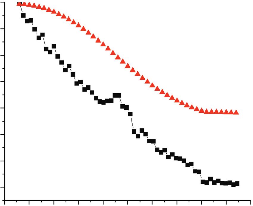
10                                                                                                                                                       Advances in Civil Engineering

                                                                                     6000

                            Temporary inverted arch stress of 1-pilot tunnel (kPa)
                                                                                     5000

                                                                                     4000

                                                                                     3000

                                                                                     2000

                                                                                     1000

                                                                                        0
                                                                                             0       5       10     15     20     25      30   35   40
                                                                                                                  Construction sequence
                                                                                                 Scheme I
                                                                                                 Scheme II
                       Figure 11: Time-history curve of temporary inverted arch stress of 1-pilot tunnel.

                                                                                     10000
                                        Middle wall stress of 1-pilot tunnel (kPa)

                                                                                      8000

                                                                                      6000

                                                                                      4000

                                                                                      2000

                                                                                        0

                                                                                             0       5       10     15     20     25      30   35   40
                                                                                                                  Construction sequence
                                                                                                 Scheme I
                                                                                                 Scheme II
                                   Figure 12: Time-history curve of middle wall stress of 1-pilot tunnel.

As shown in Table 3, the maximum stress value and the                                                                     5.3.4. Overall Comparison. Figure 13 shows the overall
stress value at the completion of tunnel excavation of the                                                                stress diagram of the tunnel support structure when the
middle wall in scheme II were 12.4% and 5.5% higher                                                                       tunnel was excavated at 10 m according to different schemes.
than those in scheme I, respectively.                                                                                     The stress of the tunnel support structure in scheme I was
    To sum up, the stress values of initial support and                                                                   small in the spandrel, hance, and temporary inverted arch,
temporary support in scheme II were higher than those in                                                                  and the stress was mainly concentrated in the vault, middle
scheme I, but both were within the controllable range.                                                                    wall, arch foot, and arch bottom. The maximum tensile stress
Therefore, when scheme II was adopted for construction,                                                                   was 7.71 MPa located in the middle wall on the right side.
it was necessary to strengthen the monitoring of the                                                                      The maximum compressive stress was −0.65 MPa located in
supporting structure, especially the temporary inverted                                                                   the initial support on the right side. Because of the con-
arch, to ensure the construction safety.                                                                                  struction off the upper part of the supporting structure only,
Advances in Civil Engineering 11
(a)
(b)
Figure 13: Overall stress diagram of the tunnel support structure. (a) Overall stress diagram of the tunnel support structure in
scheme I. (b) Overall stress diagram of the tunnel support structure in scheme II.
the stress of hance and temporary inverted arch in scheme II same, which showed that the simulation of the de-
were larger than that in scheme I. The maximum tensile formation law of the stratum by this model was
stress was 9.86 MPa located in the temporary inverted arch basically consistent. Based on this model, the exca-
on the right side. The maximum compressive stress was vation sequence of the double-side heading method
−0.98 MPa located in the initial support on the right side. could be qualitatively researched.
Therefore, the lower part of the structure could share the (2) Compared with the original construction scheme,
load of the upper part of the structure and improve the safety the optimized construction scheme had a higher
and stability of the overall structure. impact on the supporting structure, especially the
temporary inverted arch, but it was within the
6. Conclusion controllable range. The optimized construction
scheme first excavated the upper section of the
According to the numerical simulation data, after analyzing
tunnel and then the lower section, which solved the
the surface displacement, displacement, and stress charac-
problems of the large height difference in the tunnel
teristics of the supporting structure of the double-side
and difficulty in transporting workers, machines, and
heading method under different excavation sequences, the
materials, increased the construction work surface,
conclusions were as follows:
greatly improved the construction efficiency, and
(1) By comparing the numerical simulation date and shortened the construction period. The optimized
monitoring data of transverse passage surface set- construction scheme can provide a reference for the
tlement, it could be seen that the variation law of construction of urban subway tunnels under similar
surface settlement between the two methods was the engineering conditions in the future.12 Advances in Civil Engineering
Data Availability Great Wall station of Beijing-Zhangjiakou high-speed rail-
way,” Modern Tunnelling Technology, vol. 56, no. S2,
All data, models, or codes that support the findings of this pp. 578–584, 2019.
study are available from the corresponding author upon [13] F. Liu, W. Zheng, L. Li, W. Feng, and G. Ning, “Mechanical
reasonable request. and fatigue performance of rubber concrete,” Construction
and Building Materials, vol. 47, pp. 711–719, 2013.
[14] F. Liu, G. Chen, L. Li, and Y. Guo, “Study of impact per-
Conflicts of Interest formance of rubber reinforced concrete,” Construction and
Building Materials, vol. 36, no. 11, pp. 604–616, 2012.
The authors declare that they have no conflicts of interest.
[15] W. Feng, F. Liu, F. Yang, L. Li, and L. Jing, “Experimental
study on dynamic split tensile properties of rubber concrete,”
Acknowledgments Construction and Building Materials, vol. 165, pp. 675–687,
2018.
The authors gratefully acknowledge the financial support [16] Y. Guo, J. Xie, J. Zhao, and K. Zuo, “Utilization of unpro-
provided by the National Natural Science Foundation of cessed steel slag as fine aggregate in normal- and high-
China under Grant no. 51978177. strength concrete,” Construction and Building Materials,
vol. 204, pp. 41–49, 2019.
References [17] Y. C. Guo, S. H. Xiao, J. J. Zeng, J. Y. Su, T. Z. Li, and Z. H. Xie,
“Behavior of concrete-filled FRP tube columns internally
[1] B. B. Yang and Y. Liu, “Application of fractals to evaluate reinforced with FRP-steel composite bars under axial com-
fractures of rock due to mining,” Fractal and Fractional, vol. 6, pression,” Construction and Building Materials, vol. 315,
no. 2, pp. 1–15, 2022. pp. 1–18, Article ID 125714, 2022.
[2] B. Yang, S. Du, X. Zhao, D. Tang, and C. Yang, “Decision [18] Y. Wu, J. Cui, J. Huang, W. Zhang, N. Yoshimoto, and
making of curriculum attainment degree for engineering L. Wen, “Correlation of critical state strength properties with
geology based on fuzzy set theory,” Advances in Civil Engi- particle shape and surface fractal dimension of clinker ash,”
neering, vol. 2021, Article ID 1743778, 6 pages, 2021. International Journal of Geomechanics, vol. 21, no. 6, Article
[3] B. Yuan, Z. Li, Z. Zhao, H. Ni, Z. Su, and Z. Li, “Experimental ID 04021071, 2021.
study of displacement field of layered soils surrounding lat- [19] B. Bai, Q. Nie, Y. Zhang, X. Wang, and W. Hu, “Cotransport
erally loaded pile based on Transparent Soil,” Journal of Soils of heavy metals and SiO2 particles at different temperatures
and Sediments, vol. 21, no. 9, pp. 3072–3083, 2021. by seepage,” Journal of Hydrology, vol. 597, Article ID 125771,
[4] X. Que, Z. Zhu, Z. Niu, and W. Lu, “Estimating the strength 2021.
and deformation of columnar jointed rock mass based on [20] L. Wang, G. Li, X. Li et al., “Influence of reactivity and dosage
physical model test,” Bulletin of Engineering Geology and the of MgO expansive agent on shrinkage and crack resistance of
Environment, vol. 80, no. 2, pp. 1557–1570, 2021. face slab concrete,” Cement and Concrete Composites, vol. 126,
[5] Y.-C. Guo, Y.-Y. Ye, G. Guan-Lin, J.-F. Lv, Y.-L. Bai, and Article ID 104333, 2022.
J.-J. Zeng, “Effective usage of high strength steel tubes: Axial [21] L. Wang, X. F. Song, H. M. Yang et al., “Pore structural and
compressive behavior of hybrid FRP-concrete-steel solid fractal analysis of the effects of MgO reactivity and dosage on
columns,” Thin-Walled Structures, vol. 154, Article ID 106796, permeability and F–T resistance of concrete,” Fractal and
2020. Fractional, vol. 6, no. 2, pp. 1–17, 2022.
[6] B. Yuan, Z. Li, Z. Su, Q. Luo, M. Chen, and Z. Zhao, “Sen- [22] L. Wang, R. Y. Luo, W. Zhang, M. M. Jin, and S. W. Tang,
sitivity of multistage fill slope based on finite element model,”
“Effects of fineness and content of phosphorus slag on cement
Advances in Civil Engineering, vol. 2021, Article ID 6622936,
hydration, permeability, pore structure and fractal dimension
13 pages, 2021.
of concrete,” Fractals, vol. 29, no. 2, Article ID 2140004, 2021.
[7] B. Yang, J. Liu, X. Zhao, and S. Zheng, “Evaporation and
[23] B. X. Yuan, M. Sun, L. Xiong, Q. Z. Luo, S. P. Pradhan, and
cracked soda soil improved by fly ash from recycled mate-
H. Z. Li, “Investigation of 3D deformation of transparent soil
rials,” Land Degradation & Development, vol. 32, no. 9,
around a laterally loaded pile based on a hydraulic gradient
pp. 2823–2832, 2021.
[8] J. Xiao, X. Long, W. Qu, L. Li, H. Jiang, and Z. Zhong, model test,” Journal of Building Engineering, vol. 28, no. 3,
“Influence of sulfuric acid corrosion on concrete stress-strain Article ID 1010124, 2020.
relationship under uniaxial compression,” Measurement, [24] B. Yuan, M. Sun, Y. Wang, L. Zhai, Q. Luo, and X. Zhang,
vol. 187, Article ID 110318, 2022. “Full 3D displacement measuring system for 3D displacement
[9] J. Xiao, Z. M. Xu, Y. K. Murong et al., “Effect of chemical field of soil around a laterally loaded pile in transparent soil,”
composition of fine aggregate on the frictional behavior of International Journal of Geomechanics, vol. 19, no. 5, Article
concrete–soil interface under sulfuric acid environment,” ID 04019028, 2019.
Fractal Fract, vol. 6, no. 1, pp. 1–23, 2022. [25] B. Yuan, L. Xiong, L. Zhai et al., “Transparent synthetic soil
[10] C. Liu, “Analysis of influence of different excavation methods and its application in modeling of soil-structure interaction
on stability of highway tunnel,” Highway Engineer, vol. 44, using optical system,” Frontiers of Earth Science, vol. 7, p. 276,
no. 1, pp. 130–134, 2019. 2019.
[11] Y. C. Zhang, G. W. Hu, and Z. X. Xin, “Comparative analysis [26] S. T. Li, Z. S. Tan, and W. T. Du, “Analysis on the mechanical
and selection of construction methods for large section loess behavior of the small spacing highway tunnel with super large
tunnel,” Journal of Railway Engineering Society, vol. 27, no. 3, cross section,” China Civil Engineering Journal, vol. 50, no. S2,
pp. 87–92, 2010. pp. 292–296, 2017.
[12] J. Y. Liu, G. Lv, M. Q. Zhang, L. Yue, and D. H. Luo, “Study on [27] W. Zhou, “Scheme optimization and monitoring analysis of
extra-large span tunnel excavation methods for Badaling large section shallow buried tunnel on existing highway,”Advances in Civil Engineering 13
Journal of Xi’an University of Architecture and Technology,
vol. 52, no. 4, pp. 520–527, 2020.
[28] D. P. Ren, “Construction technology of variable Cross⁃section for
Three⁃line bifurcation and Large-span section of railway tunnel,”
Railway Engineering, vol. 61, no. 12, pp. 105–108, 2021.
[29] S. Q. Liu, J. H. Guo, Y. Yue, and H. W. Shen, “Influence sim-
ulation of different underground excavation methods on surface
settlement for underground station built in hard rock area,”
Urban Mass Transit, vol. 24, no. 3, pp. 142–146, 2021.
[30] N. Liu, K. Chen, X. Y. Liu, and S. H. Fu, “Study on excavation
technology of rock column in double tunnel of subway sta-
tion,” Journal of Railway Science and Engineering, vol. 17,
no. 9, pp. 2320–2327, 2020.
[31] L. C. Yang, S. H. Zhou, and Y. M. Yao, “Ground surface
settlement during excavation of variety span tunnel,” Journal
of Tongji University, vol. 04, pp. 408–412, 2003.
[32] W. Deng, X. F. Shi, G. L. Yang, and H. Q. Zhang, “Analysis of
numerical modeling and mechanical characteristics of large
section tunnel,” Highway, vol. 63, no. 3, pp. 253–259, 2018.
[33] Y. L. Zhang, G. Y. Wang, Z. Q. Li, and X. P. Wu, “The study on
the influence of excavation parameters of deep buried and
large-section tunnel,” Construction Technology, vol. 43, no. S2,
pp. 116–119, 2014.
[34] B. Zhu and X. J. Shi, “Study on construction of long span and
soft rock tunnel with numerical simulation,” Applied Me-
chanics and Materials, vol. 2733, pp. 438-439, 2013.
[35] Y. L. Shang and Z. Tan, “Optimization of mined construction
method for the super-large section Liuhualu station of
Guangzhou metro,” Modern Tunnelling Technology, vol. 56,
no. 3, pp. 177–185, 2019.
[36] S. Zeng, “Construction procedure optimization of double-
sidewall guide pit method for large-section subsurface ex-
cavation subway station,” Municipal Engineer, vol. 41, no. 1,
pp. 152–155, 2019.
[37] Y. Yang, J. L. Huang, B. H. Wan, R. J. Liang, X. J. Wei, and
X. Cai, “Research on construction optimization of shallow
buried large section railway tunnel crossing pebble soil,”
Journal of Railway Science and Engineering, vol. 18, no. 5,
pp. 1240–1247, 2021.
[38] X. D. Li and W. Wang, “Case study on construction of shallow
metro tunnel by double side heading method with core rock
kept,” Tunnel Construction, vol. 35, no. 10, pp. 1060–1065,
2015.
[39] H. Rohola, “Advance numerical simulation of tunneling by
using a double shield TBM,” Computers and Geotechnics,
vol. 57, 2014.
[40] B. X. Yuan, Z. H. Li, Y. M. Chen et al., “Mechanical and
microstructural properties of recycling granite residual soil
reinforced with glass fiber and liquid-modified polyvinyl al-
cohol polymer,” Chemosphere, vol. 268, no. P1, Article ID
131652, 2021.
[41] Z. Song, Z. Cao, J. Wang, S. Wei, S. Hu, and Z. Niu,
“Optimal analysis of tunnel construction methods through
cross passage from subway shaft,” Advances in Civil En-
gineering, vol. 2018, no. 3, Article ID 5181954, 14 pages,
2018.
[42] B. X. Yuan, Z. J. Li, W. J. Chen et al., “Influence of groundwater
depth on pile–soil mechanical properties and fractal character-
istics under cyclic loading,” Fractal Fractional, vol. 6, no. 4,
pp. 1–20, 2022.
[43] B. Bai, R. Zhou, G. Cai, W. Hu, and G. Yang, “Coupled thermo-
hydro-mechanical mechanism in view of the soil particle rear-
rangement of granular thermodynamics,” Computers and Geo-
technics, vol. 137, no. 8, Article ID 104272, 2021.You can also read