Review of Interconnection in Modular Structures - ACA ...
←
→
Page content transcription
If your browser does not render page correctly, please read the page content below
Research Article                                                                                                                                     20-23 June
                                                                                                                                                           2021
Review of Interconnection in Modular Structures
Betül Karacalı, Merve Sağıroğlu Maali
Department of Civil Engineering, Architecture and Engineering Faculty, Erzurum Technical University, Erzurum, Turkey.
Corresponding Author E mail:merve.sagiroglu@erzurum.edu.tr            Corresponding Author ORCID: 0000-0001-8717-0800

Keywords                                    Abstract
modular steel structures, modular           Modular structures have just emerged in the building industry. Modules are manufactured
structural connections, innovative          at the factory, transported to the site and assembled on site by means of a tower crane. The
connection types                            size of the modules is limited by the vehicle carrying the modules. Because modular
                                            structures are repeatable and manufactured in the factory, they are low in cost, fast to build,
                                            high quality, and less risky in terms of security. The most important component of modular
                                            structures are connections. Because the connections greatly affect the stability, tolerance,
                                            oscillation, strength, strength and behavior of the structure. However, it is quite difficult to
                                            understand the performance of the connections. Therefore, a lot of work needs to be done on
                                            the connections.

1. Introduction
The modules that generate the modular buildings are assembled
internally and externally at the factory and transported to the on site,
and the modules are combined in the field through inter-modular
connections as seen Fig.1. The size of the module is limited by the size
of the transport vehicle. The figure shows the module sizes allowed by
the rules for the road[1]. Due to the repeatability of the modules, these
buildings are mostly used in hotels and student residence. Modular
structures are not preferred in retail, parking area or mixed-use
buildings that require wide column spacing. Since modular structures
are repeatable, they provide less waste and fast assembly. Modular
structures ensure safety and high quality, as the modules are
manufactured in the factory under controlled conditions. In modular
structures, modules are reusable and easy to assemble and
disassemble because they are combined thanks to inter-module
connections. Since the modules are produced in the factory
environment, they cause little disturbance to the environment in
terms of noise and pollution. Although modular structures have many
advantages over traditional buildings, they also have some                                        Figure 1. Assembly process of modular structures[1]
disadvantages. Factory production facilities are more costly because
the modules are manufactured in the factory. Modular buildings have                    2. Structural systems for modular buildings
many structural challenges, there is a need to better understand the
performance of modular structures, but engineers have little                           2.1. 2D Panelised systems
experience with modular building[2].
                                                                                       In 2D modular systems, as seen Fig.2., columns or walls are installed
                                                                                       first, and then the panels are placed on the vertical elements. The
                                                                                       connections used in this type of system connect the panels to each
                                                                                       other and provide load transmission between the panels[3].

                       PACE 2021- Ataturk University, Engineering Faculty, Department of Civil Engineering, Erzurum, 25030, TURKEY 20-23 June 2021
                                                                                                                                                                  1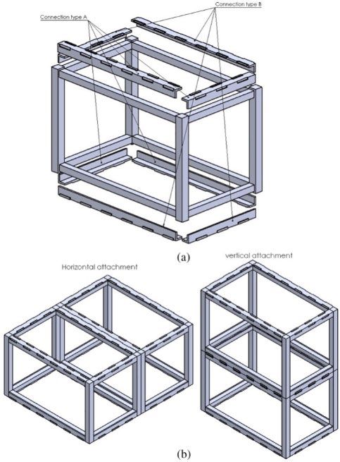
Karacalı and Sağıroğlu Maalı
2.3. Hybrid Core Systems
As the height of the structure increases, the lateral height increases,
so the size of the elements of the submodules is larger. A hybrid core
system, in Fig.5.(a),can be used to avoid this disadvantage. In this
system, the core added to the structure meets the lateral loads and
reduces the lateral deformation[3].
2.4. Hybrid Podium Systems
Since modular buildings cannot be used in large span areas, hybrid
podium systems, Fig.5.(b), are used to eliminate this disadvantage. In
this system, the lower floors (usually the first two floors) are
Figure 2. 2D Panelised system[4] constructed using a long space steel or concrete frame. Then the
modular segment of the building is placed above the podium[3].
2.2. 3D Systems 2.5. Frame Unit Systems
Assembling a 2D system is more complicated than a 3d system. In the frame system, in Fig.5.(c), the primary structure of the building
However, the 2d system is more flexible than the 3d system. 3D system is the traditional frame. After the frame is installed, the modules are
is more suitable for projects with high repeatability[4]. The 3D modular placed between the structural members of the frame[3].
system is divided into two according to the way of load transfer; Load-
bearing wall systems and corner supported frames[3].
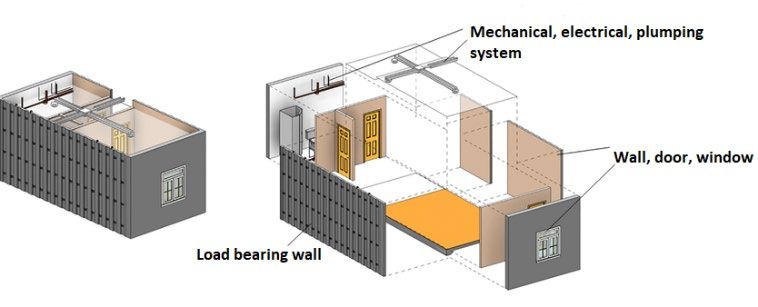
2.2.1. Load-Bearing Wall Systems
In load-bearing wall systems, vertical loads (dead and live loads) are
transmitted to the walls and then transmitted from the walls to the
foundations. The load-bearing members of this type of modular are
the walls, as seen Fig.3. These modules comprise of cold formed C-
sections that repeat along the wall[3].
Figure 5. (a)Core system (b)Podium system (c)Frame unit system[4]
3. Connection Systems
Figure 3. Load bearing wall system[1] Connections greatly affect the performance of a modular building.
Therefore, this study focuses on modular connections. In modular
structures,as seen Fig.6, connections are divided into three; module-
foundation connection, intra-module connection, inter-module
2.2.2. Corner-Supported Systems connection.
Corner supported systems, Fig.4, carry the vertical loads coming from
the side beams of the modules. In this system, which mostly has
columns at its corners, steel hollow profiles (SHS) are generally used
for the columns. In this type of modular system, columns and beams
carry vertical loads, while some support elements or coatings bear
lateral loads[3].
Figure 6. Modular connection system[5]
3.1. Module to foundation Connection
Foundations are built before the modules come to the construction
site. Basing on the construction site and ground conditions, almost
any system can be used in the foundations. Every connection system
has its advantages and disadvantages. For example, the main
Figure 4. Corner supported system[1] connection type, chain / cable / keeper plate, is cheap but has
limitations in low-rise buildings. Welding to the base layer in the field
is stiff connecting but it requires extra cost onsite and has impair to
steel corrosion. Foundations in steel buildings usually consist of
precast concrete footings and bored pile. In multi-storey modular
buildings, foundation connections are important because as the
PACE 2021- Ataturk University, Engineering Faculty, Department of Civil Engineering, Erzurum, 25030, TURKEY 20-23 June 2021
2
Karacalı and Sağıroğlu Maalı

lateral loads increase, if the modules are not attached to the                        connection with tie rod, inter connection with connector and inter
foundation sufficiently, overturning and slip failure may occur[5].                   coonection with bolt [4].

3.2.      Intra-module Connection                                                     Connections are made on site and are repeatable. Therefore, it affects
                                                                                      the structural performance of the building more than intra - module
Traditional methods are used to connect the elements that make up a                   connections and foundation- module connections[9]. Although a
module. Bolted and welded joints usually are used in intra modules.                   detailed understanding of modular interconnections is needed,
Bolted connections usually include single fin plates, double angle                    experimental and numerical studies on connections are very limited.
cleats and bolted end plates. Bolted connections are easy to dismantle
and reuse later. However, since it offers relatively low moment                       There are several innovative connection types developed for
capacity, rotational capacity and ductility, the joints need to be                    interconnects in modular steel buildings. Since modular
strengthened. Welds are available for factory assembly[5].                            interconnections require a lot of workmanship onsite such as laying
                                                                                      rebar, site grouting for concrete modular buildings, the assembly
3.3.      Inter-module Connection                                                     speed decreases and thus the benefits of modular structures are
                                                                                      eliminated[4]. Therefore, the connections of concrete modules are not
Interconnections are divided into three according to their types;                     included in this study.
bolted, welded and composite connections. Bolted connections are
widely used in modular structures as they require little site work and                Interconnections can be categorized into three types: inter connection
can be disassembled easily. Bolted connections must be pre-drilled                    with tie rod, inter connections with connector, and inter connection
during the molding process and are manufactured to accommodate                        with bolt[4].
shear and strain. However, the use of long slotted holes can result in
the potential for increasing tolerance and failure to slip under great                4.      Inter-module connections
horizontal force. Nevertheless slip of connection can be controlled
using the friction grip or pre-tensioned bolts force[5].                              4.1.        Horizontally connected techuniques

On the other hand, welds provide good stiffness so they can be used
in modular structures. However, it requires a lot of onsite work and is
very costly to dismantle. This goes against the purpose of modular
structures. Sometimes, concrete or grout is used to fasten the
connection in-place. Thus, composite concrete-steel connection is
formed[5].

This connection includes a vertical connection (VC) that fasten the
modules overlapping as illustrated in Fig.7.(a) or a horizontal
connection (HC) that fasten the modules that are next to each other as                     Figure 8.(a)Horizontally connected with tie plate[6] (b) bolted side
illustrated Fig.7.(b). Moreover interconnections may also contain both
vertical connection and horizontal connection. Interconnections                                                             plate[6]
provide load transfer between modules and transfer the loads of
overlapping modules to the foundation[6].
                                                                                      Bolted connections are frequently used in modular structures as
                                                                                      they are easy to assemble and disassemble in the field. Fig.8. The
Interconnections also provide building tolerance, overall stability,
                                                                                      connection shown in (a) is connected horizontally using a tie plate,
load distribution, alternative load paths in modular steel buildings in               and the connection shown in (b) is connected horizontally using a
case a certain load path does not occur. Therefore, interconnections                  bolted side plate.[6]
are the most important element affecting the structural performance
of modular steel structures.
                                                                                      4.2.        Vertically connected techuniques

Figure 7. (a)vertical interconnecting (b)horizontal interconnecting[6]

Modules are essentially strong enough to carry vertical loads without
additional resistance system. Thanks to interconnections,
diaphragms transmit lateral loads to other modules or external lateral
load resistance system. Therefore, diaphragm movement of the                                  Figure 9. Rod connection using plugin bar and prestressed
modules depends on the strength of the interconnections[7].                                                               tendon[10]
However, since each module has its own structural element (floor,
column, beam, etc.), the diaphragms of modular buildings are                          The fig.9. shows details of the pre-stressed modular connection. End
discontinuous. Diaphragm discontinuity, which is a big problem, can                   of each column has holes for pre-stressed strand or plugin bars.
lead to flexible diaphragms. Under seismic loads, if high-rise modular                Thanks to the a range of strand connectors placed in the connecting
buildings have flexible diaphragms, faults in the lateral load                        area of the column ends as stabilizers, the pre-tension level can be
distribution, excessive drift and collapse may occur[8].                              controlled and when the strand inside the column are damaged, the
                                                                                      other column is not affected by this situation. There is a shear block
In addition, gradual collapse of the building may occur in extreme                    at the column end to resist shear force. In order to prevent crushing
situations such as fire, explosion, loss of support, blows.                           of the concrete and increase the ductility, plugin bars are placed in
Interconnections can be catagorized into three types: Inter                           the joint area and these bars are extended along the column. During
                                                                                      on-site assembly, the upper module is aligned upon the bottom
                      PACE 2021- Ataturk University, Engineering Faculty, Department of Civil Engineering, Erzurum, 25030, TURKEY 20-23 June 2021
                                                                                                                                                                  3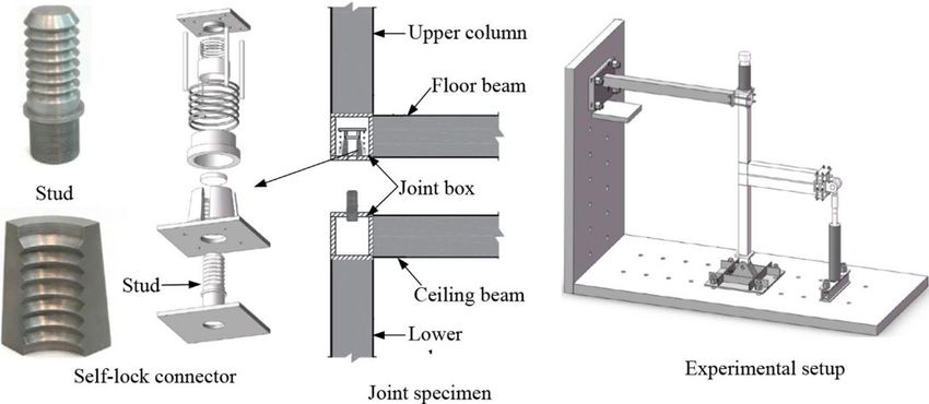
Karacalı and Sağıroğlu Maalı

module and strands and bars are placed in the holes. Then the                          are directly proportional and the increase in the contact area causes
tendons were brought to the desired stress point, fixed with                           a slight increase in the shear load. A new connection type is suggested
connectors and finally concrete poured into the module columns                         by looking at the load-slip behavior of the connection[12].
through holes. The two-storey prestressed modular frame is subjected
to cyclic loads at different earthquake levels. The frame offered
sufficient rigidity and ductility at frequently occurring earthquake
levels. However, as the load transfer resistance was exceeded between
the concrete, the plugin bars and the strands, shear and span
occurred. This led to a decrease in strength and rigidity and crushing
of the concrete. The experimental results of this connection have been
verified by the finite element method[10].

                                                                                                          Figure 12. Connector with self-lock[13]

                                                                                       The joint boxes, seen fig.12, placed in the module corners are welded
                                                                                       to the module columns and beams. The stud is interpolated into the
                                                                                       upper part of the bottom module. Other parts of the connector is
                                                                                       placed inside the joint box in the upper module. A hole is drilled in the
                                                                                       lower surface of the joint box in the upper module for mounting.
                                                                                       During the assembly phase, the upper module is aligned on the bottom
                                                                                       module. When the stud is inserted into the mounting hole of the joint
                                                                                       box in the upper module, the connection is automatically locked.
            Figure 10. Rod connection using steel box[11]                              Cyclic testing and pull out testing were performed to analyze the
                                                                                       structural performance of the connection. At the end of the pull out
The innovative inter-module connection, in fig.10, that connects the                   test, it was observed that the joint showed good tensile behavior and
columns of the bottom and upper modules vertically, has a steel box                    the tensile strength was mainly dependent on the stud diameter and
with sloped upper and lower edges and a post-tensioned rod in middle                   material properties. The failure mode was found not to be due to
of the steel box. Beams of the module are welded off-site to the                       slippage, but to fracture in the weakest part of the stud. At the same
columns. Steel boxed specimens with different thicknesses and                          time, excellent seismic performance of the connection has been
specimens with different initial post-tensioning loads experienced                     observed. The failure mode of the connection resulted from fracture
quasi-static cyclic loading testing. Also, two samples, one fully welded               and buckling in the beam root[13].
and one partially welded, were used to compare with post-tensioned
connections. The results showed that the post-tensioned joint had
sufficient lateral resistance and showed better cumulative energy
dissipation and higher stiffness distortions. It was observed that the
maximum displacement of the sample with the thinnest steel box and
without initial post-tensioning load was less[11].

                                                                                               Figure 13. Connector connection using corner fitting[14]

                                                                                       This connection, seen fig.13, used in the modular building in China
                                                                                       consists of corner fittings and connectors. The connector includes a
                                                                                       connecting plate and a nut. There are access openings on both sides
                                                                                       of the corner fitting to hoist the module and to rotate the nut. In the
                                                                                       assembly phase of the connection, first the lower and upper corner
          Figure 11. Rod connection using threaded rod[12]                             fittings are aligned, then the nut is tightened from the access
                                                                                       openings in the corner fitting with the help of a specific bar. Both
In this design, in fig.11, there is a threaded rod and a shear key inside              experimental and finite element methods are used to understand the
the hollow steel section that makes up the modules. The P1 plate,                      rotational stiffness of the connection. Flexural test was performed to
which has a centre hole to let the threaded rod to pass through, is                    understand the structural behavior of the connecting. Buckling is
welded to shear key and the p2 plate to the columns. The access                        observed in the upper plate of the lower corner fitting[14].
opening ensured in the module columns lets the rod to be inserted
through the modules and be tensioned. However, since a rod is used
in the connection, the bar must have a larger diameter. this causes
tension. On the other hand, while this connection provides a vertical
connection thanks to the connecting rod, the horizontal connection is
not considered in this design. The sliding behavior of the joint was
investigated experimentally by changing the coating surface, contact
surface area and preload. The results showed that those with sandy
surfaces increase the slip factor and thus provide more slip
resistance. It has been observed that the bolt preload and shear load
                       PACE 2021- Ataturk University, Engineering Faculty, Department of Civil Engineering, Erzurum, 25030, TURKEY 20-23 June 2021
                                                                                                                                                              4
Karacalı and Sağıroğlu Maalı

4.3.      Both vertically and horizontally connected techniques                        As seen in the fig.16, this connector can be connected to beams and/or
                                                                                       columns or connectors can be attached to each other. Therefore, this
                                                                                       connection offers both horizontal and vertical connections between
                                                                                       stacked modules. This cube-shaped connection used in China has
                                                                                       holes on all faces for bolt mounting. Both experimental and numerical
                                                                                       methods have been used to investigate the loading capacity of this
                                                                                       connection. The behavior of this connection in shear and tension,
                                                                                       failure mode and loading capacity are analyzed by experimental
                                                                                       methods. Then, the structural performance of the connection was
                                                                                       investigated by the finite element method. Shear loading test and
                                                                                       simply supported test were performed and the results showed that the
                                                                                       connections failed because the bolts exceeded the tensile capacity[17].

             Figure 14. Rod connection using tie plate[15].

While the steel connection plate provides a horizontal connection
between the modules, the threaded steel bar fixed with the nut
provides a vertical connection as seen fig.14. The steel bar resists the
tension forces and avoids it from separating vertically While the
columns resist the compression forces, shear forces are countered by
the shear key[15].                                                                               Figure 17. Bolted connection using plugin device[18]

                                                                                       In the proposed modular interconnection, the plugin device, which
                                                                                       has four tubes, provides horizontal connection, while high-strength
                                                                                       bolts provide vertical connection. By welding the intermediate and
                                                                                       cover plate of the beams of the modules, local buckling of the beam's
                                                                                       plate against the tensile force of the bolt is avoided. This connection
                                                                                       does not require welding on site. During assembly, as seen fig.17, the
                                                                                       columns of the module are inserted into the plug-in device. When the
                                                                                       columns are placed, a horizontal connection is automatically
                                                                                       provided with the effect of clamping. Finally, long bolts will be
                                                                                       inserted through the holes in the beams of the modules, thus the
                                                                                       connection will be completed. In this connection, the samples were
                                                                                       classified according to whether they were stiffening or not and the
                                                                                       size of the samples, and they experienced static monotonic loading
                                                                                       test, quasi-static cyclic loading test and numerical analysis. The
       Figure 15. Connector connection using gusset plate[16]                          results showed that gap was created between the modules' columns
                                                                                       and the plug-in device, and the gap increased as lateral force
Module units, consisting of column, floor-ceiling beams HSS sections,                  increased. As soon as the lateral displacement attained a critical
are connected by vectorbloc connector from the corners. The                            value, cracks were observed in the beam-column joint area. In
connector is connected to the HSS sections with a full penetration                     addition, local buckling has been observed in the columns[18].
fillet weld. The gusset plate, which is connected to the lower module
using FHCS onsite, establishes a horizontal connection between the
modules. After, as seen fig.15, the upper module is installed into the
bottom module via the registration pin. Finally, with the socket head
cap screws(SHCS) assembly, the modules are combined vertically. The
joint has experienced axial tension and axial compression testing to
understand the behaviour of the joint. Based on the rigidity and
strength of the connection, the position of the SHCS screws has been
found to play an important role. As the axial tensile load increased,
abrupt breakage was observed in the SHCS screws. Therefore, the joint
is fragile and requires improvement in order for it to fail ductilely[16].

                                                                                        Figure 18. Bolted connection using gusset plate and cover plate[19]

                                                                                       All structural elements of the module consist of HSS. For the assembly
                                                                                       of the connection shown in the fig.18, first of all, a part of the columns
                                                                                       is cut in the factory. Holes are drilled for mounting the bolt on the
                                                                                       column cover plate and the outer surface of the column. In addition,
                                                                                       holes are drilled in the cross-shaped gusset plate, which provides both
                                                                                       horizontal and vertical connections, corresponding to these holes. In
                   Figure 16. Bracket connector[17]                                    the field, firstly, the cruciform gusset plate is placed between the two
                                                                                       bottom modules. upper modules are placed on the lower modules.

                       PACE 2021- Ataturk University, Engineering Faculty, Department of Civil Engineering, Erzurum, 25030, TURKEY 20-23 June 2021
                                                                                                                                                               5
Karacalı and Sağıroğlu Maalı
Lastly, the cut part of the column is closed by welding the cover plate.
Four different samples, fortified and non-reinforced, were examined
under cyclic load. Reinforced ones exhibited greater moment
resistance capacity than non-reinforced ones. Generally, local
buckling, plastic joint progress was observed in the samples. In
addition, a fracture was observed in the column-beam junction
area[19].
Figure 19. Bolted connection using bling bolt[20]
A connection plate with blinds and high-tension bolts was used to
connect four adjacent modules. Hollow structural steel (HSS) used for
columns is attached to blind bolted connection plate. A cold formed C Figure 21. Bolted connection using plate[22]
section used for ceiling and floor beams is attached to a normal high
tension bolted connection plate. In total, as seen fig.19, ten blind bolts This connection, as seen fig.21, provides both vertical and horizontal
and eight high tension bolts are used. Two types of samples were connections and is designed to transfer vertical and horizontal loads.
designed to understand the structural performance of beam-to- This load transfer occurs by bolting the columns of the adjacent
column connection, and knee brace was used in one of the two modules. Three types of fastening were studied depending on the size
samples to understand bending stiffness. The results showed that of the bolt and type of the bolt hole. The behavior of the connection
knee pads play an important role in the rigidity and strength of the under lateral loads has been investigated using both experimental
connection[20]. and numerical methods. The sliding behavior of the bolts has been
observed under great lateral forces. Large slots are not recommended
in high-rise modular buildings as larger deflections occur as the slip
gets larger[22].
Figure 20. Different types of bolted connections[21]
Modular units are usually connected using high strength bolts and
connection plate, but the performance of the column decreases as
holes are drilled to use bolts. In order to compensate for this situation,
bolts and connection plate used without drilling holes are used in this
connection. As shown in the fig.20, L, T and cross shaped connection
types can be standardized according to the module assembly. These
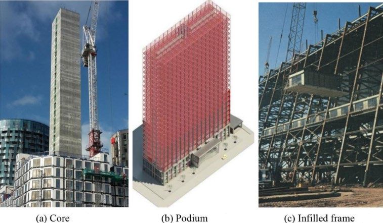
Figure 22. Bolted connection using locating pin[23]
connection types can be easily assembled, disassembled and reused.
To analyze the seismic behavior of the junction, cyclic loading testing The recommended locking connection is seen in the fig.22. This
was performed and the structural performance of the connection was connection allows to combine a total of eight modules, with four
investigated. Three specimens with bolts of different shapes were modules on the top and four modules on the bottom. While horizontal
analyzed by experimental and numerical methods. In addition, a connection is provided with P2 plate, vertical connection is provided
welded specimen was produced to compare with these specimens. The by means of bolts. The locating pins are welded to the p1 plate at the
welded specimen exhibited greater initial stiffness and greater factory. P1 and P3 plates are welded to the ends of the module
maximum moment than bolted specimens. It was also observed that columns. The P2 plate is then placed on the P1 plate and the P3 plate
as the size of the connection decreased, the stiffness decreased[21]. on the P2 plate. Finally, the plates are fastened with pre-stressed bolts.
In order to understand the F-d behavior of the connection, both
experimental tests and numerical methods were used. The presence
of both locating pins and bolts in the connection caused an increase
in shear resistance. In addition, it was observed that as the preload of
the bolt changes, the slip resistance changes and the hole tolerance
has little effect on the slip resistance[23].
PACE 2021- Ataturk University, Engineering Faculty, Department of Civil Engineering, Erzurum, 25030, TURKEY 20-23 June 2021
6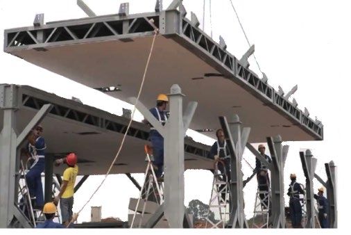
Karacalı and Sağıroğlu Maalı
conceptual lifting of the supports. Modular interconnections are
based on forces arising from loss of support.[7]
Conclusions
In this study, modular structures are introduced and modular
building types are mentioned. The importance of connections in
modular structures is explained and the proposed innovative
connection types are examined.
References
[1.] Liew, J.Y.R., Y.S. Chua, and Z. Dai, Steel concrete composite
systems for modular construction of high-rise buildings.
Figure 23. Bolted connection using connector plate(a),using resilient Structures, 21 (2019), 135-149.
layer(b), using column plate[24] [2.] Rostek, M., Constructing steel modular buildings with varying
interconnections. Massachusetts Institute of Technology. (2018)
The fig.23. shows three types of connection types can transfer both [3.] Ramaji, I.J. and A.M. Memari. Identification of structural issues
vertical and horizontal loads. In the connection shown in figure a, a in design and construction of multi-story modular buildings. in
steel plate is placed between the column plates. This steel plate Proceedings of the 1st residential building design and
reduces the seismic energy generated by the modules and helps the construction conference. (2013)
connection's energy consumption. In the connection in figure b, both [4.] Thai, H.T., T. Ngo, and B. Uy, A review on modular construction
steel plate and flexible plate made of rubber material are used. This for high-rise buildings. Structures, 28 (2020), 1265-1290.
[5.] Lacey, A.W., et al., Structural response of modular buildings - An
flexible plate provides additional damping. Having the same column
overview. Journal of Building Engineering, 16 (2018), 45-56.
dimensions as fig. a and b, the connection in figure c consists only of [6.] Lacey, A.W., et al., Review of bolted inter-module connections in
column plates and bolts. These connection types were compared in modular steel buildings. Journal of Building Engineering, 23
terms of energy loss and seismic performance using the finite (2019), 207-219.
element method. The joints in Fig a and b showed better ductility and [7.] Sharafi, P., et al., Interlocking system for enhancing the integrity
better performance than the joints in fig c. The performance of flexible of multi-storey modular buildings. Automation in construction,
plate and steel plate a and b plates is improved. Connection B is 85 (2018), 263-272.
recommended for use in steel modular structures in terms of ductility, [8.] Srisangeerthanan, S., et al. Influence of Diaphragm Flexibility on
energy and seismic resistance[24]. the Seismic Performance of Multi-Story Modular Buildings.
Australian Earthquake Engineering Society Conference, (2017)
[9.] Srisangeerthanan, S., et al., Review of performance requirements
for inter-module connections in multi-story modular buildings.
Journal of Building Engineering, 28 (2020)
[10.] Chen, Z., et al., Research on pretensioned modular frame test and
simulations. Engineering Structures, 151 (2017), 774-787.
[11.] Sanches, R., O. Mercan, and B. Roberts, Experimental
investigations of vertical post-tensioned connection for modular
steel structures. Engineering Structures, 175 (2018), 776-789.
[12.] Lacey, A.W., et al., Shear behaviour of post-tensioned inter-
module connection for modular steel buildings. Journal of
Constructional Steel Research, 162 (2019), 105707.
[13.] Dai, X.-M., et al., Experimental study on seismic behavior of a
novel plug-in self-lock joint for modular steel construction.
Engineering Structures, 181 (2019), 143-164.
[14.] Chen, Z., et al., Rotational stiffness of inter-module connection in
mid-rise modular steel buildings. Engineering Structures, 196
(2019), 109273.
[15.] Chua, Y., J.R. Liew, and S. Pang, Modelling of connections and
lateral behavior of high-rise modular steel buildings. Journal of
Constructional Steel Research, 166 (2020), 105901.
[16.] Dhanapal, J., et al., Structural performance of state-of-the-art
VectorBloc modular connector under axial loads. Engineering
Structures, 183 (2019), 496-509.
[17.] Doh, J.H., et al., Steel bracket connection on modular buildings. J
Steel Structure Construction, 121 (2016), 2472-0437.
[18.] Chen, Z., J. Liu, and Y. Yu, Experimental study on interior
connections in modular steel buildings. Engineering Structures,
147 (2017), 625-638.
[19.] Deng, E.-F., et al., Seismic behavior and design of cruciform
bolted module-to-module connection with various reinforcing
details. Thin-Walled Structures, 133 (2018), 106-119.
Figure 24. Interlocking system[7] [20.] Cho, B.-H., et al., Structural performance of a new blind-bolted
frame modular beam-column connection under lateral loading.
This connection is easier to set up compared to other connections Applied Sciences, 2019, Vol 9, No 9, 1929.
since the movements made during assembly are simple. The two [21.] Lee, S., et al., Verification of the seismic performance of a rigidly
strips in the figure are intertwined to avoid rotation and any connected modular system depending on the shape and size of
separation. The figure shows the resistance of the connection to shear the ceiling bracket. Materials, 2017, Vol 10 No 3, 263.
and pressure, which is subjected to any load. As seen in the figure, this [22.] Gunawardena, T., Behaviour of prefabricated modular buildings
subjected to lateral loads. 2016.
combination provides both horizontal and vertical connections. The
[23.] Lacey, A.W., et al., New interlocking inter-module connection for
modules are clamped with a simple push action, thus ensuring modular steel buildings: Experimental and numerical studies.
structural integrity. The structural performance of this connection is Engineering Structures, 198 (2019), 109465.
found by static and dynamic horizontal loading. The structural
integrity of modular buildings against accidental loads is found by
PACE 2021- Ataturk University, Engineering Faculty, Department of Civil Engineering, Erzurum, 25030, TURKEY 20-23 June 2021
7
Karacalı and Sağıroğlu Maalı

[24.] Sendanayake, S.V., et al., Seismic mitigation of steel modular
      building structures through innovative inter-modular
      connections. Heliyon, 2019, Vol 5, No 11, e02751.

                     PACE 2021- Ataturk University, Engineering Faculty, Department of Civil Engineering, Erzurum, 25030, TURKEY 20-23 June 2021
                                                                                                                                                   8
You can also read