Influence of environment and aging materials on the performance of solar chimney power plants - Renewable Energy and Environmental ...
←
→
Page content transcription
If your browser does not render page correctly, please read the page content below
Renew. Energy Environ. Sustain. 6, 11 (2021)
© S.M. Boualleg et al., published by EDP Sciences, 2021
https://doi.org/10.1051/rees/2021013
                                                                                                                     Available online at:
                                                                                                                     www.rees-journal.org

    RESEARCH ARTICLE

Influence of environment and aging materials on the performance
of solar chimney power plants
Salim Mekki Boualleg1,2,*, Salah Larbi1, Amor Bouhdjar3, Dalila Amokrane2, and Abdallah Sofiane Berrouk4
1
    Mechanical Engineering Department, Ecole Nationale Polytechnique, 10, Avenue Hassen Badi, El Harrach 16200, Algiers,
    Algeria
2
    Departement des Energies Nouvelles et Renouvelables, Institut Algérien du Pétrole, Avenue du 1er Novembre 35000,
    Boumerdes, Algeria
3
    Centre de Développement des Energies Renouvelables, Bouzareah, Algeria
4
    Mechanical Engineering Department, Khalifa University of Science and Technology, United Arab Emirates

            Received: 9 February 2021 / Received in final form: 25 March 2021 / Accepted: 25 March 2021

            Abstract. The simplicity of solar chimney power plant (SCPP) makes it very attractive for power generation.
            This paper investigates the technical feasibility of using a locally-produced plastic film (Low-Density Poly-
            Ethylene “LDPE”) as a solar chimney power plant collector cover. The idea is to combine a very low-cost material
            with a simple technical solution. As LDPE is subject to deterioration, the effect of aging on the initial properties
            of the used material is analyzed. Natural aging was privileged over the accelerated one by exposing the studied
            film, for a time duration of 3 years, to environmental constraints similar to the local conditions where the SCPP
            collectors are installed. Various experimental tests were carried out to show the decrease of mechanical
            resistance and to confirm the structural degradation. Results showed that after an exposure time of 3 years, a
            decrease of more than 50% of the failure stress is recorded. The spectroscopic analysis confirmed the progressive
            degradation of the structure of the aged films. Pyranometric measurements showed that the transmittance of the
            film proportionally decreases with the duration of aging which has a direct impact on the SCPP collector
            performance. A mathematical model is developed and validated to simulate the performance of the SCPP. An
            increase in the initial dimension of the collector by about 23% is necessary to maintain the design-targeted
            production during an exploitation period of three years. The study concluded that this type of film can be used in
            SCPP collectors for a maximum life cycle of 3 years under the considered environmental conditions.

1 Introduction                                                              very attractive for sunny countries like Algeria. It presents
                                                                            many advantages, such as its simple design which can
The Global Energy Scenario reveals that renewable sources                   provide about 200 MW of electric power while being safe,
from biofuels, wind energy and solar energy will have the                   reliable and requiring minimum maintenance. However, a
highest contribution in the energy mix in the next future                   commercial SCPP is a very huge structure. The economic
[1]. This will reduce the concentration of carbon dioxide,                  optimization of such power plant can be achieved using
CO2, in the atmosphere and hinder the increase of the                       cheap construction materials for collectors in order to offset
earth’s average temperature [1].                                            the significant cost linked to building chimneys made of
     In its energy transition policy, Algeria is targeting to               concrete.
produce 22 GW of renewable energies by 2030, through its                        SCPP consists of three main components: the solar
displayed national program (Algerian Ministry of Energy)                    collector, the chimney tower and the turbine (Fig. 1).
[2]. However, the technological choice is a key component of                Historically, Prof. Bernard Dubos proposed in 1926 the
sustainable development. In this view, the technological                    construction of a SCPP in North Africa to the French
simplicity of solar chimney power plant (SCPP) makes it                     Academy of Sciences [3]. The first solar chimney power
                                                                            plant prototype 50 kW was built in Manzanares, Spain. It
                                                                            had a braced metal chimney of 194.6 m high, 0.00125 m
* e-mail: salimmekki.boualleg@gmail.com;                                    thick and a collector with a radius of 122 m, covered by a
salim_mekki.boualleg@g.enp.edu.dz                                           plastic and glass roof [4].

This is an Open Access article distributed under the terms of the Creative Commons Attribution License (https://creativecommons.org/licenses/by/4.0),
             which permits unrestricted use, distribution, and reproduction in any medium, provided the original work is properly cited.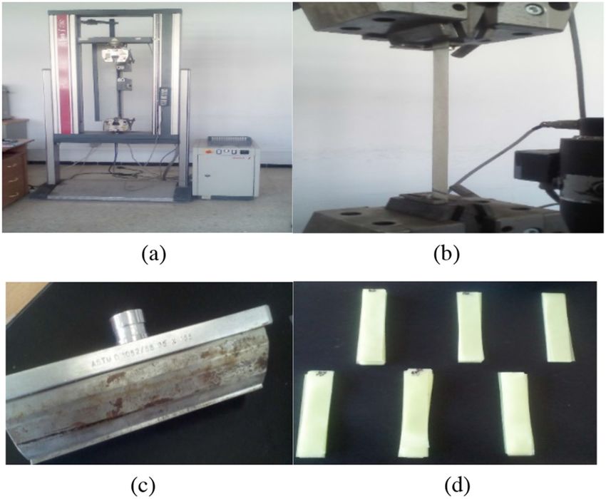
2                              S.M. Boualleg et al.: Renew. Energy Environ. Sustain. 6, 11 (2021)

                                                                conventional one, which can reduce considerably the large
                                                                solar collector.
                                                                    One year later, the authors [13] proposed the
                                                                hybridization of the prototype with photovoltaic panels
                                                                and reported that system’s efficiency increased by about
                                                                2%. In order to highlight the impact of the collector roof
                                                                height on the SCPP performance, Ayadi et al. [14] built an
                                                                experimental prototype at the University of Sfax, Tunisia,
                                                                North Africa. They concluded that a decrease in the height
                                                                of the collector roof yield to an increase in the generated
                                                                power. However, they did not give any reference to the
                                                                value of the optimal height of the collector related to the
                                                                dimension of the structure. A review by Molana et al. [15]
                                                                reported that experimental studies were mainly focused on
                                                                small-scale systems. The study did not analyze the impact
                                                                of aging on the performance of the system. The research
                                                                strongly suggested the building of large power plants to
                                                                provide more reliable references for theoretical and
                                                                modeling studies. It concluded that the choice of materials
                                                                mainly depends on the resulting power generating costs. In
                                                                their review article, Penghua et al. [16] demonstrated that
    Fig. 1. Main components of a solar chimney power plant.     with the research and development of construction
                                                                technology, new materials, and novel concepts, the SCPP
                                                                will possibly play an important role in increasing energy
                                                                supplies, by improving the energy mix, and alleviating
                                                                environmental concerns.
    Haaf et al. [4] and Haaf [5] analyzed the energy balance,       Al-Kayiem et al. [17] investigated the enhancement of
the design criteria and the cost analysisof SCPPs. The          a solar chimney, by recovering thermal waste energy of
authors showed that the use of a plastic film of PVC and         exhaust gases to heat the air in the solar chimney
PVF offers an optimal recovery time of 3.6 years for a 36       collector.
MW SCPP. The Manzanares prototype of the solar                      In their study, Nasraoui et al. [18] performed a new
chimney power plant operated for eight years (from 1982         collector design with double-pass counter flow mode, which
to 1989) [5]. This pioneering work has been followed by         allowed the increase of its efficiency by 28%. In their study,
many theoretical and experimental studies for modeling          Siamak et al. [19] proposed the use of a semi-transparent
large scale SCPP. Based on an analytical model, Schlaich        photovoltaic panels as the collector roof of a solar chimney
[6] demonstrated that there are no optimal dimensions for a     collector for economic enhancement of the system. Using a
solar chimney. However, if the cost of implementation is        three-dimensional simulation, Seyyed et al. [20] compared
taken into consideration, the plant can be optimized            the case of collector with natural and artificial roughness.
thermodynamically. This conclusion showed the impor-            They investigated its impact on the performance of SCPP
tance of the present work as it investigates the use of         in the region of Semnan, Iran. Sedighi et al. [21]
cheaper material. In their research, Schlaich et al. [7] and    investigated the effects of soil porosity on the output
Schlaich and Schiel [8] analyzed the extrapolation of           power and energy efficiency of SCPP. They found that land
experimental data from the prototype of Manzanares to           with less porosity and a location with high radiation is the
large power plants (5, 30 and 100 MW).                          most suitable place for the construction of solar chimney
    Located in the Jinshawan desert region of Inner             power plant.
Mongolia, the Wuhai SCPP [9] prototype was connected                Papadakis et al. [22] explained that testing methods
to the grid in October 2010. The various measurements           used for plastics in general, are also applied to greenhouse
showed that the surrounding winds have a significant             covers despite important functional differences. Hence the
influence on the airflow inside this plant. In 2011, Najmi        urgent need for establishing widely accepted internation-
et al. [10] suggested the use of asphalt or rubber at the       ally testing methods and standards for testing the physical
bottom of the collector, a double glazed glass for the roof     properties of greenhouse covering materials. In their
with a reduction of collector height to 1.3 m to increase the   review, the authors underlined the excellent radiation
power of the system.                                            transmissivity of LDPE films. They reported that, this
    In a comparative investigation of different analytical      covering material is dominant and most inexpensive plastic
models, Boualleg et al. [11] pointed out that the different     film in the Mediterranean regions.
studies presented in the literature, considered constant            Dehbi et al. [23] investigated the influence of different
physical material parameters through the life cycle of          exposure times of natural ageing on the mechanical
SCPP exploitation. Dogan et al. [12] experimented a new         behavior of mono-layer and tri-layers LDPE films used
concept of perforated solar collector to enhance the            as greenhouse cover. The authors explained that the design
performance of SCPP. The authors reported that the              of tri-layers film makes it possible to slow down the
collector efficiency is three times higher than the              deterioration of the film, making it more durable.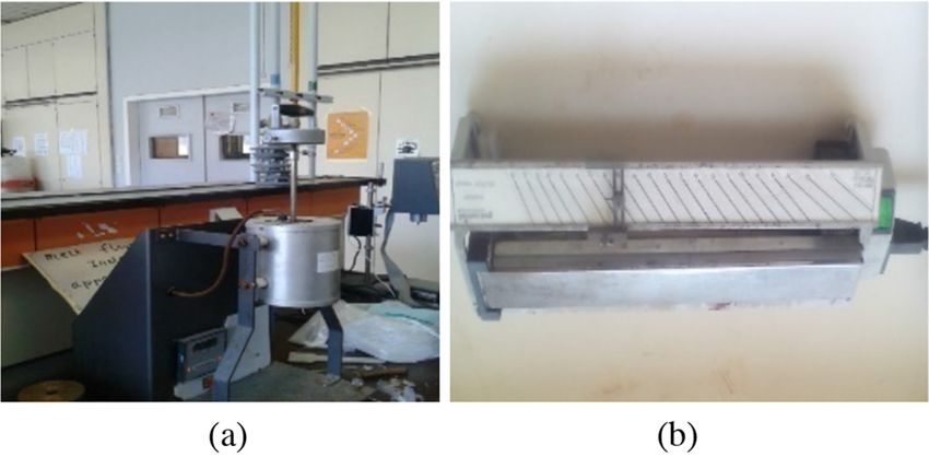
S.M. Boualleg et al.: Renew. Energy Environ. Sustain. 6, 11 (2021)                             3

     Dilara et al. [24] discussed several methods for testing
the mechanical properties of greenhouse polyethylene
films. Also, the factors affecting ageing of LDPE used as
greenhouse covering are presented. The authors reported
that the artificial ageing testing can only provide a rough
estimate of the actual behavior of the plastic film when
exposed to the real and complicated environmental factors
that affect the plastic during its use.
     The review of the previously published studies showed
few works that carried out experimental studies and
evaluated effect of ambient conditions on properties of the
materials. The different simulation models, in the
literature, assume constant thermo-physical properties
without any loss in power production even when using
polymers canopy for the experimental setup. The present
work goes beyond the evaluation of the material degrada-
tion, by analyzing its impact on the performance of SCPP
and, the reduction of solar transmittance on the system
efficiency.
     This study investigates the impact of aging on the
performance of the SCPP facility by analyzing the use of
greenhouse stabilized LDPE film for mainly two reasons:
(i) enhance the economic efficiency of these power plants by      Fig. 2. LDPE specimen used in greenhouse located in Boumerdes.
using cheaper material and, (ii) demonstrate the impact of
aging on the SCPP performance.
                                                                 A photo-degradation study of non-stabilized transparent
2 SCPP collector description                                     and non-colored polyethylene films Adelhafidi et al. [27]
                                                                 reported that after 8 months of exposure time, the samples
                                                                 became too brittle to not resist the wind force. In the
The solar collector (SC) is the part of SCPP, which              present study a yellowish stabilized LDPE is considered.
produces hot air by the greenhouse effect. With a roof made
of glass or clear plastic film, SC covers a very large area of
several thousand square meters. The choice of the material       3 Experimental protocol
covering this type of collector has a direct and important
impact on the initial investment, and hence the importance       Since the plastic cover of a solar chimney collector is
of the choice of the material to be used [6].                    subjected to mechanical and climatic constraints (irradia-
     Indeed, covering the huge collector structure, up to        tion, wind, rain, high temperature gradients ...), this will
several hectares, with low density polyethylene (LDPE),          accelerate its degradation. The performance of a SCPP
will reduce the initial investment costs, as well as the         collector will be influenced by these phenomena and hence
duration of the pay-back period, making the SCPP more            impact the efficiency of the whole system. Prior to
economically attractive. However, the degradation of the         degrading the film, a characterization of new (virgin)
film affects its performance. It alters its mechanical and        samples was carried out.
photo-thermal performance and consequently reduces the
overall efficiency of the system.                                 3.1 Aging polyethylene films
     In this view, the LDPE film, produced locally and
widely used in agricultural greenhouses in Algeria, can be       To privilege the natural aging, the same film was used in a
interesting as an alternative solution to glass based on its     greenhouse installed in the region of Boumerdes (Fig. 2)
low price and physical and thermal properties. The popular       and exposed to environmental constraints similar to that of
use of plastic is due in part to its cheapness and to the fact   a SCPP installed in the same region.
that there is not a single form of plastic but a multitude          At different exposure times, samples were tested
with specific properties for each. They can be rigid or           (1 month, 2 months, 1 year, 2 years and 3 years).
flexible, transparent or opaque, electrically insulating or       Mechanical, Hardness, rheological, physical, spectroscopic
semiconductors, insensitive to moisture, and lightweight         and photo-thermal tests were performed on sample films of
compared to glass [25]. In addition, the multitude of            the same nature.
manufacturing processes makes it possible to easily obtain
and without machining complex forms. However, polymers           3.2 Mechanical properties
often deteriorate in outdoor applications. The most
important cause of degradation is solar irradiation; the         A tensile test was performed according to ISO 1184 standard
lifetime of plastics depends mainly on the climate.              using a rectangular form and a speed of 100 mm/min. This
The higher the temperature, the faster the chemical              test determined the strength at break, Young’s modulus and
reactions making plastics vulnerable in hot climates [26].       elongation at break (Fig. 3).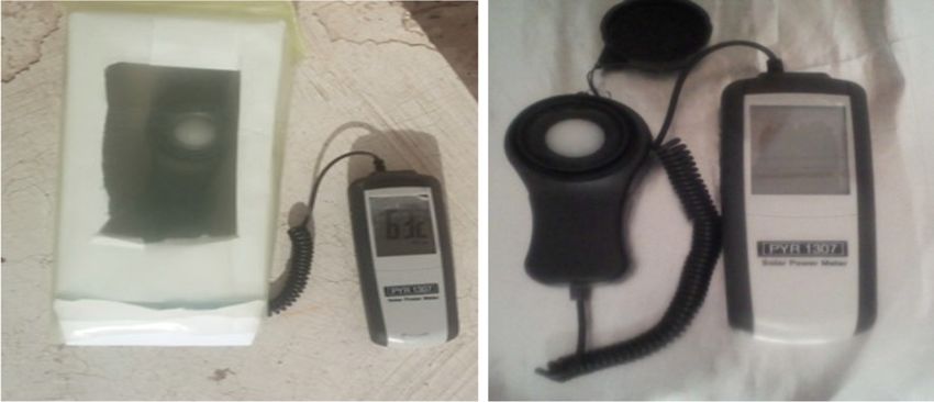
4                                S.M. Boualleg et al.: Renew. Energy Environ. Sustain. 6, 11 (2021)

                                                                      Fig. 5. Polymer rheological laboratory at IAP: (a) The melt flow
                                                                      index tester; (b) Kofler bench.

Fig. 3. Tensile Test performed at Polymer laboratory IAP:
(a) Device for tensile tests on plastic films, (b) Parallel clamping
specimen grips (c) Matrix for specimen cutter (d) Specimens to be
tested.

                                                                      Fig. 6. Spectroscopic Laboratory IAP: (a) UV-Visible spectro-
                                                                      photometer (b) Fourier Transform Infrared Spectrophotometer.

     Fig. 4. Hardness tester at Polymer laboratory IAP.

   The Hardness test was performed according to ISO
868–1978 shore A (Fig. 4).

3.3 Rheological properties
3.3.1 Flow rate index                                                        Fig. 7. Photo thermal measurement dispositive.

The melt flow index (MFI) was done according to the
standard ISO 1133–1918 (F) using the temperature of
190 ± 0.5 °C and a load of 2160 g (Fig. 5a).                          determination prior to following the evolution of degradation
                                                                      of LDPE samples (Fig. 6).
3.3.2 Melting temperature
                                                                      3.6 Photo thermal properties
Measurement of the melting temperature was determined
using “Kofler bench” (Fig. 5b).                                        Measurement of the global and incident direct solar
                                                                      radiation was performed by means of a pyranometer.
3.4 Physical properties                                               The test was firstly performed without a film barrier;
                                                                      secondary inside boxes covered with virgin, and finally with
The density was carried out according to the ISO 1186                 aged films to compare the transmittance as a function of
standard using the immersion method.                                  the exposure time. The used dispositive is shown in
                                                                      Figure 7. It consists of a box with an opening. The opening
3.5 Spectroscopic methods                                             is covered with a sample from the tested film. Cares were
                                                                      taken to avoid shadow effect on the measurement, which
Spectroscopic ultraviolet-visible (UV-Visible) and infrared           makesthe estimation of solar transmittance of the film
(IR) measurements were performed mainly for a qualitative             possible.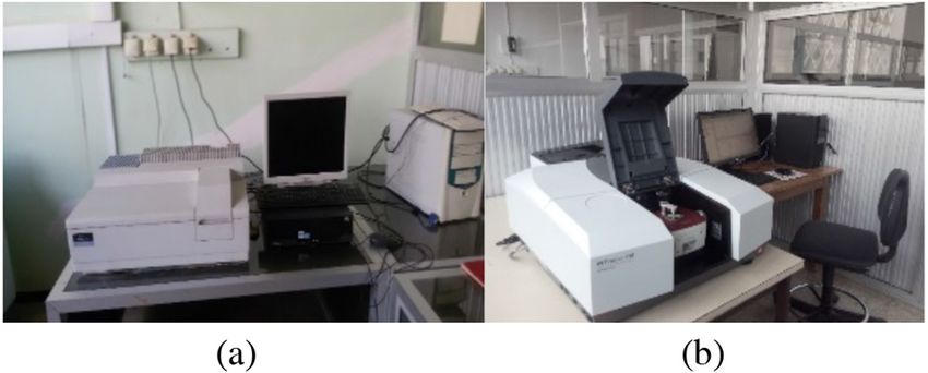
S.M. Boualleg et al.: Renew. Energy Environ. Sustain. 6, 11 (2021)                                5

Table 1. Characteristics of the virgin plastic film sample.

Properties                                                                  Results                            Units
Melt Flow Index (MFI)                                                       0.66 ± 0.007                       g/10 min
Density (r)                                                                 0.913 ± 0.011                      g/cm3
Melting temperature (Tf)                                                    123                                °C
Hardness                                                                    56 ± 3.22                          Shore A
                                          Longitudinal                      1.76 ± 0.04
Young’s modulus (E)                       Transversal                       1.95 ± 0.10                        10E9 N/mm2
                                          Longitudinal                      21 ± 0.91
Stress at break (s)                       Transversal                       21 ± 0.63                          N/mm2
                                          Longitudinal                      537.31 ± 20.58
Elongation at break (e)                   Transversal                       758.61 ± 17.2                      %

4 Results and discussion
To ensure the data reproducibility, large square samples
sides were cut, at each ageing period, from the same main
cover, and sufficient test samples were prepared to conduct
the experiments required, with respect to the recommen-
dations of the used standard.

4.1 Virgin film characterization

The obtained results related to the virgin film being
considered in this study are reported in Table 1. The
obtained value of the MFI is that of a polyethylene (PE)
grade used for an injection-blowing process (Recueil de
norms SdandardISO 21 [28]). Regarding density, the               Fig. 8. Stress at break of LDPE in longitudinal direction.
obtained result shows that it is in the range of [0.91–
0.92 g/cm3] (Recueil de normes ISO 21, 1984). The melting
temperature of the film was 123 °C. This result is included
in the melting temperature range of low density poly-
ethylene [100, 125 °C]. In conclusion, the results of the
melting point and density tests confirm that the new virgin
film is a low-density polyethylene type.

4.2 Aging film characterization
4.2.1 Tensile test
Figures 8 and 9 represent the stress at break of aged
samples versus the exposure time in the two directions
longitudinal and transversal respectively (Longitudinal
direction refers to the extruding machining direction
during the plastic film production process; the opposite
direction of the sample is the transversal direction). The
                                                                 Fig. 9. Stress at break of LDPE in transversal direction.
obtained results show that the stress at break decreases
considerably as a function of exposure time. It should also
be noted that this decrease is a function of the climatic
conditions, depending on the months and season, as is the         Dehbi et al. [23] used a milky colored LPDE present on
case for 1 and 2 months of exposure where the variation is    the market. The new sample of mono layer LDPE reviled
not very significant and remains of the same order of          very low stress at break of about 2 MPa [23], when it should
magnitude for both directions (longitudinal and transver-     be of a minimum of 8 MPa [29]. They found that lifetime of
sal). After an exposure of 3 years, however, a considerable   this type of mono-layer LDPE is around 5 onths, and when
reduction of more than 50% of properties is observed.         multi layering the film it doubles the cover life time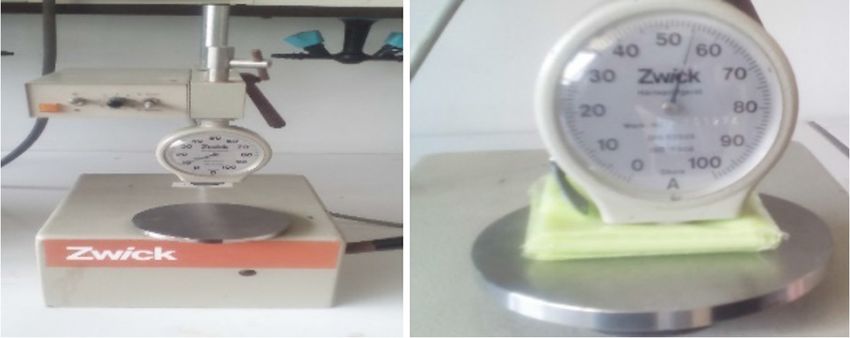
6                             S.M. Boualleg et al.: Renew. Energy Environ. Sustain. 6, 11 (2021)

                                                                     Fig. 11. Elongation at break of transversal LDPE.
     Fig. 10. Elongation at break of longitudinal LDPE.

Table 2. Hardness results of the films.

Measurements                 Virgin              1 month               2 months             24 months           30 months
1                            55                  58                    53                   48                  45
2                            61                  53                    52                   46                  43
3                            57                  53                    50                   48                  44
4                            51                  56                    47                   43                  46
5                            56                  57                    57                   47                  42
Average (Shore A)            56 ± 1.61           55.4 ± 1.02           51.8 ± 1.65          46.4 ± 0.92         44 ± 0.70

reaching 10 months for tri-layers film. In the present case,
the yellowish green film reached a 3 years life time and
registered an initial sbreak of 21 Mpa. Those results are in
good agreement with [22] and [29].
    Figures 10 and 11 show the variation of the elongation
at break as a function of time in the two directions
(longitudinal and transversal respectively). A similar trend
with the tensile stress was obtained. A significant decrease
in elongation at break as a function of exposure time is
observed after an exposure of 3 years.
    A similar trend with the tensile stress was obtained. A
significant decrease in elongation at break as a consequence
of exposure time is observed after an exposure of 3 years.
    Figures 12 and 13 illustrate the variation of Young’s
modulus as a function of the exposure time in both                    Fig. 12. Young’s modulus of longitudinal LDPE.
directions.
    The obtained results show an evolutionary decrease of
the modulus of elasticity for the aged film compared to the     4.3 Spectroscopic tests
new samples.                                                   4.3.1 UV-Visible spectroscopy

4.2.2 Hardness test                                            Figure 14 representing UV-Visible spectroscopy results
                                                               showed that the new PE film has a minor absorption band
The obtained results of hardness shore A for virgin and        at 308 nm, indicating the presence of chromophores or
aged samples are summarized in Table 2.                        double bonds. Such results may be due either to the
    It can be noted from the obtained results that the         primary antioxidants, additives used to stabilize the film
hardness shore A decreases with the duration of exposure       from thermo-oxidative degradation, or to the dye, an
and this is a function of the climatic constraints (wind,      additive used for coloration (yellow pigment). After aging,
temperature, rain, solar radiation, humidity). These results   new peaks appear mainly at 319, 321, 323 and 327 nm for
are in agreement with the tensile tests.                       films aged 1, 2, 18 and 36 months, respectively. The
S.M. Boualleg et al.: Renew. Energy Environ. Sustain. 6, 11 (2021) 7
Fig. 13. Young’s modulus of transversal LDPE.
Fig. 15. FTIR results of the new and naturally aged films.
Fig. 14. UV-Visible spectroscopy results of new and aged
samples.
Fig. 16. Transmitted solar irradiation on the 18th of July 2019,
intensity and frequency of these peaks increase with the measured for direct incident solar irradiation, and incident
duration of exposure. These traduce the increase in the through a new sample, 12, 24 and 36 months exposed sample.
number of double bonds: the higher the number of double
bonds the more important is the bathochromic effect
(wavelength increases) and the hyperchromic effect
(intensity absorption increases). 880 and 3600 cm1 were observed, reflecting the presence of
N=H and O-H absorption bonds. These later are attributed
to the yellow pigment present initially in the samples.
4.3.2 Infra-Red (FTIR) spectrometry
These results are in good agreement with those obtained by
Figure 15 represents the transmittance as a function of UV-Visible spectroscopy.
wavenumber for the naturally aged films in comparison
with the new one. The obtained results illustrate the 4.4 Photo-thermal measurement
presence of a peak at 1734 cm1 corresponding to C=O
absorption. Knowing that PE is apolyolefin polymer, such The measurements were performed on the 18th of July
result is may be due to antioxidants or pigments structure. 2019, a summer day with a clear sky. The obtained results
It has been also noticed that the peak intensity of C=O of solar irradiation and transmitted radiation through
bond increases with film aging. Furthermore, two peaks at virgin and 3 years aged sample are shown in Figure 16.8 S.M. Boualleg et al.: Renew. Energy Environ. Sustain. 6, 11 (2021)
Defining the transmittance as t ¼ II0 , where I0 and I are
direct and indirect incident irradiation measured without
and through film obstacle, respectively. The average solar
radiation transmission t, of a new sample is about 80%,
which is in the range of transmittance of the plastic film
[70–95%] as reported in [22]. It reaches 78% after one-year
exposure (12 months). It decreases to 72% in the second
years and 64% after 3 years exposure. This corresponds to a
progressive reduction of solar transmission of 2.5%, 10%
and 20% during the first, the second and the third year,
respectively. These results are consistent with the results
obtained by FTIR spectrometry as degradation increase
with aging duration leads to a transmittance reduction. As
the incident energy converted to heat by the system is
proportional to t, the reduction of the film transmittance
will reduce the overall effective energy produced by the
system. This will be investigated in more details in the next
section.
5 Mathematical model
The simulation is based on an analytical model based on an
energy balance applied to the collector. Thus a relationship
between the mass air flow and the temperature gain is
introduced. This relationship will be coupled to the
chimney model, to represent the complete system. The
goal is to determine the energy produced based on
the geometric parameters and physical properties of the
system. This will allow the study of the influence of
regression of canopy properties on SCPP efficiency. The
standard equation used for modeling the SCPP is reported
in many references such as [6,11,30].
The effective produced power of the overall system can
be expressed as:
Fig. 17. Flowchart of resolution.
W eff ¼ hcoll hturb hch Acoll I 0 ð1Þ
Based on energy balance, the solar heat transferred to
Acoll
the air from inlet to outlet can be expressed as: c2 ¼ b
a
_ p DT
hcoll ðAcoll I 0 Þ ¼ mc ð2Þ
with the turbine loaded to the total power: Acoll
c3 ¼ ta I0
sffiffiffiffiffiffiffiffiffiffiffiffiffiffiffiffiffiffiffiffiffiffiffiffiffiffiffiffiffiffiffiffiffiffiffiffiffiffiffiffi a
ð1 hturb Þ2gH ch DT Equation (4) is solved numerically using the Range
vch ¼ ð3Þ
T0 Kutta method. It is illustrated by the flowchart of
resolution in Figure 17 (Tab. 4).
Combining the previous equations and conservation
equations of the collector and the chimney and rearranging
them leads to:
6 Calculation and analysis
0 1
In order to validate the presented model, Manzanares solar
B DT 3=2 C chimney measured parameters are taken as reference. The
c1 B
@
C þ c2 DT þ c3 ¼ 0 ð4Þ
DT A technical data are given in Table 3.
1þ The comparison between measured data from Man-
T0
zanares Solar Chimney Pilot Power Plant and the
with simulation shows a good agreement. The technical data
sffiffiffiffiffiffiffiffiffiffiffiffiffiffiffiffiffiffiffiffiffiffiffiffiffiffiffiffiffiffiffiffiffiffi given in Table 3 are used for the following simulation and
ð1 hturb Þ2gH ch analysis. The simulation of the SCPP using a low-density
c1 ¼ r0 cp polyethylene as a collector cover revealed a decrease of the
T0 collector thermal efficiency and the overall systemS.M. Boualleg et al.: Renew. Energy Environ. Sustain. 6, 11 (2021) 9
Fig. 18. Overall SCPP and collector efficiency evolution for LDPE canopy: New sample (t = 80), 1 year old (t = 78), 2 years old
(t = 72) and 3 years old (t = 64).
Table 3. Typical solar chimney power plant data and Table 4. Comparison between measured and calculated
dimensions used in the simulation. values.
Geometrics parameters Manzanares Parameters Measured* Calculated
prototype DT [°C] 19,5 18,8
Collector height h [m] 1.85 Weff [kW] 48,4 49,32
Collector diameter Dcoll [m] 244 vch [m/s] 15 14,5
Chimney height Hch [m] 194.6
*Measured values from Mullett [30] and Koonsrisuk et al. [31].
Chimney diameter dch [m] 10.16
Turbine efficiency hturb [%] 83
Gearing and generator efficiency [%] 90
air inside the canopy. The collector efficiency decreases by
Collector roof solar transmittance t [%] 87 11% after 2 years exposure, and 23% after 3 years as shown
Collector absorbance* a [%] 0.76 in Figure 18. This impacts the air temperature gain inside
Collector loss coefficient b [W/m2.K] 15 the collector. The temperature decrease (DT) decreases by
Ambient conditions about 2%, 8% and 16% after one, two and three years of
Ambient temperature [K] 18 + 273.15 exposure respectively (see Fig. 19).
A gradual reduction in the produced effective power is
Gravitational acceleration [m/s2] 9.81 observed (Fig. 19). The loss in production reaches 23% for
Solar irradiation [W/m2] 1000 the 3rd year corresponding to a lack of production of 10 kW
Cp Specific heat of air [J/kg.K] 1004 for an irradiation peak of I0 = 1000 W/m2.
In order to maintain the initial energy production (case
*Estimated from Yogi [32].
of low-density polyethylene) when keeping the same
properties of the Manazanares plant, it is necessary to
estimate, during the design phase, either an additional
efficiency through the years (Fig. 18). In fact, the film height of the chimney or an additional surface of the
transmittance decrease reduces the thermal efficiency of collector to compensate the loss of energy production due
the system over the years. to aging. To demonstrate this, the mathematical code was
The overall system efficiency also decreases from executed varying the height of the chimney.
hovr = 0.096% for anew sample to 0.074% for three years Figure 20 shows that the power and air velocity are
old sample (36 months). In fact, the reduction of the proportional to the chimney height. Indeed, the updraft
collector efficiency impacts the energy transmitted to the velocity is proportional to the chimney height Hch (Eq. (3)).10 S.M. Boualleg et al.: Renew. Energy Environ. Sustain. 6, 11 (2021)
Fig. 19. Manzanares SCPP simulation output for glass (t = 87)
and LDPE canopy: New sample (t = 80), one year old (t = 78),
Fig. 21. Developed power and thermal gain for different Dcoll.
two years old (t = 72) and three years old film (t = 64)
respectively.
7 Conclusion
This study investigated the implementation of polymers
LDPE, as a roof coverage for a solar chimney power
plantwith the aim to reduce the initial investment cost.
The obtained results related to the analysis and compari-
son of the different tests carried out on new and aged
samples showed that:
– The mechanical tests (tensile and hardness) illustrate a
significant loss on the properties after exposure of three
years. These results were confirmed by the spectroscopic
tests showing the progress of film degradation as a
function of time.
– Pyranometric measurements indicate that the transmit-
Fig. 20. Developed power and updraft velocity for different Hch. tance of the film decreases as a function of the duration of
aging. A notable decrease in the transmittance perfor-
mance is noted after 3 years of exposure.
This leads in an increase of air flow inside the system and – Two dimension changes to account for the loss of
consequently to the produced power. Increasing the surface efficiency over time are investigated: increasing chimney
of the collector demonstrates an increase in the effective height and collector area.In order to offset the significant
power produced due to an increase in the temperature gain cost linked to building concrete-made chimney, and for
(Fig. 21). structural constraints, to compensate the loss in
In fact, by increasing the diameter of the collector, i.e. production during plant exploitation, an additional
the surface receiving the incident radiation, additional collector surface is recommended. In the case of an
energy is transmitted to the air under the canopy, thereby LDPE this can go up to 22% of the initial surface.
improving the thermal gain. The temperature difference – The use of polymers as a core for the collector of
(DT) and the power produced are proportional to the area experimental prototypes, model validation, and simula-
of the collector (Eqs. (1) and (2)). tion over a life cycle exceeding one year must be revised.
To ensure continuous production of the design power of – The models should take into consideration the degrada-
44.74 kW for a life cycle of 3 years (t = 64%), two solutions tion of the properties of this type of material that often
are possible: either to increase the initial height of the result in a reduction of the system efficiency.
chimney by 45 m, resulting in a 23% increase in the – The present work paves the way for modeling the SCPP
chimney height, comparatively to the initial value; or to collectors, including aging effects, which lead to a better
increase the diameter of the collector by 28 m, i.e. the initial design of the system, taking into consideration the
collector area by 276 m2, resulting in an increase of 22% reduction of the SCPP performance through its life
compared with the reference surface. cycle.S.M. Boualleg et al.: Renew. Energy Environ. Sustain. 6, 11 (2021) 11
Nomenclature 6. J. Schlaich, The Solar Chimney (Axel Menges Edition,
Stuttgart, Germany, 1995)
Latin symbols 7. J. Schlaich, R. Bergermann, W. Schiel, G. Weinrebe, Design
of commercial solar tower systems utilization of solar
A Total covered area [m2] induced convective flows for power generation, in: Proceed-
ings of the International Solar Energy Conference, Kohala
a Chimney area [m2]
Coast, United States, 573–581 (2003)
D Diameter [m]
8. J. Schlaich, W. Schiel, Solar Chimneys, Encyclopedia of
I Global solar radiation [W m2] Physical Science and Technology 3, 99–109 (2004)
H Height [m] 9. Y.L. Wei, Z.K. Wu, Shed absorbability and tower structure
P Power [W] characteristics of the solar heated wind updraft tower power,
Q Heat flux [W] in: 3rd International Conference on Solar Updraft Tower
T Temperature [K] Technology, Huazhong University Of Science And Technolo-
cp Specific heat at constant pressure [J kg1 K1] gy, Wuhan, China, 1–12 (2012)
g Gravitational acceleration, 9.81 [m s2] 10. M. Najmi, A. Nazari, H. Mansouri, G. Zahedi, Feasibility
m_ Mass flow [kg s1] study on optimization of a typical solar chimney power plant,
p Pressure [N m2] Heat Mass Transfer 48, 475–485 (2012)
v Velocity [m s1] 11. S.M. Boualleg, S. Larbi, Analyse des performances énergé-
W Work [W] tiques des centrales cheminées solaires par utilisation de
R Air gas constant [J/k mol] différents modèles mathématiques. ENP (2012). www.pnst.
cerist.dz/detail.php?id=68739
Greek symbols 12. D. Eryener, J. Hollick, H. Kuscu, Thermal performance of a
transpired solar collector updraft tower, Energy Conversion
r Density [kg m3] and Management 142, 286–295 (2017)
h Efficiency [] 13. D. Eryener, H. Kuscu, Hybrid transpired solar collector
updraft tower, Solar Energy 159, 561–571 (2018)
t Collector solar transmittance []
14. A. Ayadi, A. Bouabidi, Z. Driss, M. Salah Abid, Experimental
a Collector absorbance []
and numerical analysis of the collector roof height effect on the
b Collector loss coefficient (W/m2 K) solar chimney performance, Renewable Energy 115, 649–662
(2018)
Prefix 15. A.B. Molana Sh., K. Rahmani, D. Wen, A review on solar
chimney systems, Renewable and Sustainable Energy
D Change in value Reviews 67, 954–987 (2017)
16. P. Guoa, T. Li, B. Xu, X. Xuc, J. Li, Questions and current
Subscript understanding about solar chimney power plant: a review,
Energy Conversion and Management 182, 21–33 (2019)
0 Ambient or Incident 17. H.H. Al-Kayiem, M.A. Aurybi, S.I.U. Gilani, A.A. Ismaeel,
coll Collector S. T. Mohammad, Performance evaluation of hybrid solar
ch Chimney chimney for uninterrupted power generation, Energy 166,
eff Effective 490–505 (2019)
ovr Overall 18. H. Nasraoui, Z. Driss, H. Kchaou, Novel collector design for
turb Turbine enhancing the performance of solar chimney power plant,
Renewable Energy 145, 1658–1671 (2020)
19. S. Jamali, A. Nemati, F. Mohammadkhani, M. Yari, Thermal
and economic assessment of a solar chimney cooled
semitransparent photovoltaic (STPV) power plant in
References different climates, Solar Energy 185, 480–493 (2019)
20. S. Hossein Fallah, M. Sadegh Valipour, Evaluation of solar
1. Gianpaolo Vitale, Renewable energies future perspectives chimney power plant performance: the effect of artificial
renewable, Energy Environmental Sustainability 1, 17 (2016) roughness of collector, Solar Energy 188, 175–184 (2019)
2. https://www.energy.gov.dz/?rubrique=energies-nouvelles- 21. A. Asghar Sedighi, Z. Deldoost, B. Mahjoob Karambasti,
renouvelables-et-maitrise-de-lrenergie Effect of thermal energy storage layer porosity on perfor-
3. M.A. Dos Santos Bernardes, Solar chimney power plants- mance of solar chimney power plant considering turbine
developments and advancements, INTECH Open Access pressure drop, Energy 194, 116–859 (2020)
Publisher, 2010 22. G. Papadakis, D. Briassoulis, G. Scarascia Mugnozza,
4. W. Haaf, K. Friedrich, G. Mayr, J. Schlaich, Solar chimneys, G. Vox, P. Feuilloley, J.A. Stoffers, Radiometric and thermal
part I: principle and construction of the pilot plant in properties of, and testing methods for, greenhouse covering
Manzanares, Int. J. Solar Energy 2, 3–20 (1983) materials, J. Agric. Eng. Res. 77, 7–38 (2000)
5. W. Haaf, Solar chimneys, part II: preliminary test results 23. A. Dehbi, A.-H.I. Mourad, Durability of mono-layer versus
from the Manzanares pilot plant, Int. J. Solar Energy 2, tri-layers LDPE films used as greenhouse cover: comparative
141–161 (1984) study, Arab. J. Chem. 9, S282–S289 (2016)12 S.M. Boualleg et al.: Renew. Energy Environ. Sustain. 6, 11 (2021)
24. P.A. Dilara, D. Briassoulis, Standard testing methods for 28. Recueil de normes ISO21-TOM1 & TOM2, Plastiques:
mechanical properties and degradation of Low Density Technologie-échantillonnage et propriétés, 1984 (Recueil
Polyethylene (LDPE) films used as greenhouse covering de normes ISO 21, 1984)
materials: a critical evaluation, Polym. Test. 17, 549–585 (1998) 29. S. Füzesséry, Polyéthylènes basse densité PEBD. Techniques
25. P. Nicaud, Les Matière Plastiques. Projet Troisième Rob’Ok, de l’ingénieur, Novembre 1983
Hachette Multimédia (2007) 30. L.B. Mullett, The solar chimney overall efficiency, design
26. R. Irinislimane, N. Belhaneche-Bensemra, A. Benlefki, and performance, Int. J. Ambient Energy 8, 35–40 (1987)
Valorization of regenerated LDPE by blending with EPDM in 31. A. Koonsrisuk, T. Chitsomboon, Mathematical modelling
the presence of peroxide, J. Polym. Environ. 15, 119–124 (2007) of solar chimney power plants, Energy 51, 314–322
27. A.A. Babaghayou, I.M. Chabira, S.F. Sebaa, M., Impact of (2013)
solar radiation effects on the physicochemical properties 32. D. Yogi Goswami, Principles of solar engineering Taylor &
of Polyethylene (PE) plastic film, Soc. Behav. Sci. 195, Francis Group, 6000 Broken Sound Parkway NW, Suite 300,
2210–2217 (2015) USA
Cite this article as: Salim Mekki Boualleg, Salah Larbi, Amor Bouhdjar, Dalila Amokrane, Abdallah Sofiane Berrouk, Influence of
environment and aging materials on the performance of solar chimney power plants, Renew. Energy Environ. Sustain. 6, 11 (2021)You can also read