Installation Guide System Overview, Components, Tools & Accessories, Construction Process, Installation Procedures, Bracing, Core Filling - AFS ...
←
→
Page content transcription
If your browser does not render page correctly, please read the page content below
Volume 3 – April 2019

   Installation Guide
System Overview, Components, Tools & Accessories,
Construction Process, Installation Procedures,
Bracing, Core Filling
2
     Legal statements

    Important legal statements
    Reasonable efforts have been made to ensure the accuracy of this publication; however, any information or data
    contained herein is subject to change without notice. To ensure the information you are using is correct, AFS
    recommends you review the latest technical information available on the AFS website www.afsformwork.com.au,
    or alternatively call 1300 727 237 to speak to a Technical Representative.

    The AFS logo and rediwall® mark are registered trade marks.© 2019 AFS SYSTEMS PTY LTD. No part of this
    publication may be reproduced in any form or by any means without prior written permission from AFS Systems
    Pty Ltd. All rights reserved.

     Disclaimer
    This AFS Rediwall® Installation Guide is intended to represent good building practice in achieving structural
    design of rediwall®.This section is not intended in any way by AFS to represent all relevant information required
    on a project. It is the responsibility of those using and designing rediwall®, including but not limited to builders,
    designers, consultants and engineers to ensure that the use of rediwall® complies with all the relevant National
    Construction Code (NCC) requirements such as, but not limited to structural adequacy, acoustic, fire resistance/
    combustibility, thermal, and weatherproofing provisions. All diagrams, plans and illustrations used in this section,
    including any reinforcement shown, are supplied for indicative and diagrammatic purposes only. It remains the
    responsibility of those using rediwall® to ensure that reference is made to the project engineer’s structural details
    for all construction and reinforcement requirements.

                                                        2019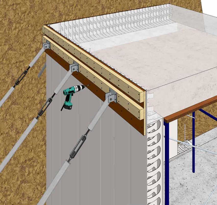
3
TABLE OF CONTENTS
   Legal statements�������������������������������������������������������������������������������������������������������������������������������� 2
   Disclaimer������������������������������������������������������������������������������������������������������������������������������������������� 2

   INTRODUCTION ����������������������������������������������������������������������������������������������4
   SYSTEM OVERVIEW����������������������������������������������������������������������������������������5
   Rediwall® Product Description������������������������������������������������������������������������������������������������������������ 8
   Rediwall® System Benefits����������������������������������������������������������������������������������������������������������������� 8

   COMPONENTS, TOOLS & ACCESSORIES����������������������������������������������������9
   Components for RW110C System������������������������������������������������������������������������������������������������������ 9
   Components for RW156C System���������������������������������������������������������������������������������������������������� 11
   Components for RW200C System���������������������������������������������������������������������������������������������������� 14
   Components for RW256S System���������������������������������������������������������������������������������������������������� 17
   Tools & Accessories ������������������������������������������������������������������������������������������������������������������������� 18

   THE CONSTRUCTION PROCESS�����������������������������������������������������������������22
   Construction Process Overview�������������������������������������������������������������������������������������������������������� 22
   Ordering������������������������������������������������������������������������������������������������������������������������������������������� 25
   How to order������������������������������������������������������������������������������������������������������������������������������������ 25

   CONSTRUCTION AND INSTALLATION PROCEDURES �����������������������������26
   Introduction�������������������������������������������������������������������������������������������������������������������������������������� 26
   Component Delivery & Worksite Layout�������������������������������������������������������������������������������������������� 27
   Floor/Wall Junction – Floor Track Installation������������������������������������������������������������������������������������� 28
   Control Joints����������������������������������������������������������������������������������������������������������������������������������� 30
   Starting Location������������������������������������������������������������������������������������������������������������������������������ 30
   Corner Construction������������������������������������������������������������������������������������������������������������������������� 31
   Wall Construction����������������������������������������������������������������������������������������������������������������������������� 32
   Wall Reinforcement��������������������������������������������������������������������������������������������������������������������������� 33
   Corner Reinforcement���������������������������������������������������������������������������������������������������������������������� 35
   Corner Reinforcement - alternate method����������������������������������������������������������������������������������������� 36
   Wall Construction����������������������������������������������������������������������������������������������������������������������������� 37
   Safety Rail/Balustrade Wall Installation���������������������������������������������������������������������������������������������� 38
   Steel Reinforcement Installation�������������������������������������������������������������������������������������������������������� 39
   T Junction Construction������������������������������������������������������������������������������������������������������������������� 40
   Obtuse Corner Construction������������������������������������������������������������������������������������������������������������� 41
   H Joiner Installation�������������������������������������������������������������������������������������������������������������������������� 43
   H-Joiner Installation (Limited Site Access)����������������������������������������������������������������������������������������� 44
   Accessory Extensions����������������������������������������������������������������������������������������������������������������������� 45
   End Cap Installation�������������������������������������������������������������������������������������������������������������������������� 46
   RW256S Blade Wall������������������������������������������������������������������������������������������������������������������������� 47
   Rediwall® Edge Form����������������������������������������������������������������������������������������������������������������������� 48
   Rediwall® J-Track Installation������������������������������������������������������������������������������������������������������������ 49
   Window Openings���������������������������������������������������������������������������������������������������������������������������� 50
   Doorway & Lintel Installation ������������������������������������������������������������������������������������������������������������ 52
   Wide Radius Curved Wall Installation������������������������������������������������������������������������������������������������ 55
   Curved Wall Reinforcement Bar Installation��������������������������������������������������������������������������������������� 56
   Stairway Landing Construction��������������������������������������������������������������������������������������������������������� 57
   Retention Tank Construction & Tanking��������������������������������������������������������������������������������������������� 58
   Lift Pit����������������������������������������������������������������������������������������������������������������������������������������������� 59
   Installation of Services���������������������������������������������������������������������������������������������������������������������� 60
   Penetrations������������������������������������������������������������������������������������������������������������������������������������� 61

   REDIWALL® TEMPORARY CONSTRUCTION BRACING�����������������������������63
   Bracing of Walls�������������������������������������������������������������������������������������������������������������������������������� 64

   CORE FILLING OF WALLS�����������������������������������������������������������������������������72

2019 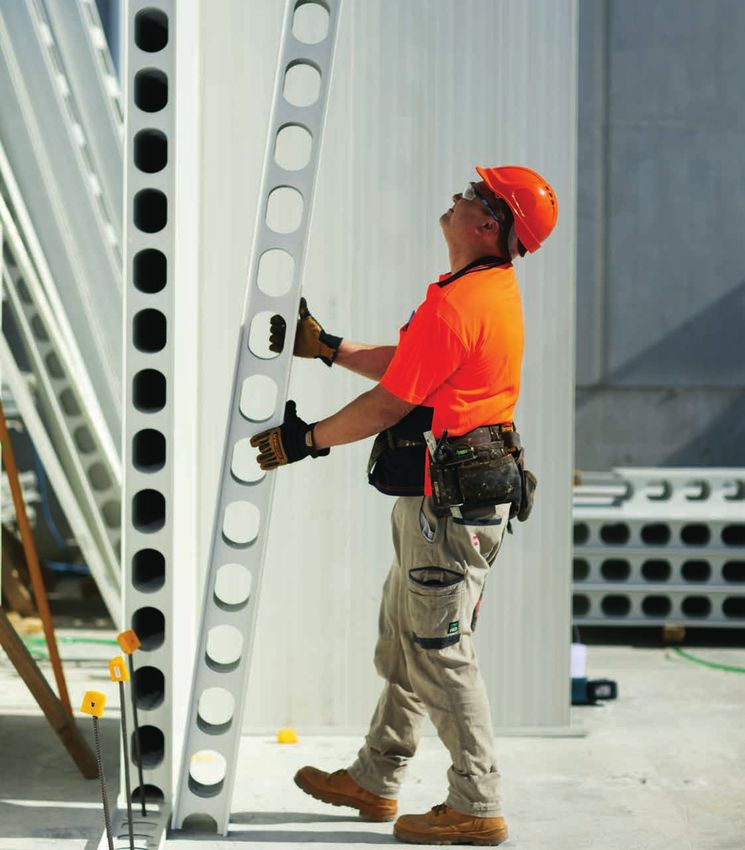
4
INTRODUCTION
This Installation Guide forms part of a comprehensive AFS Rediwall Design Guide (Vol1, Vol2 & Vol 3) which
includes chapters dedicated to Design, Performance, Compliance, Construction, Finishes and Installation of
Rediwall. This Guide should be read in conjunction with Vol 1 & Vol 2. Downloads of these chapters are available
via the Resource Centre at www.afsformwork.com.au.
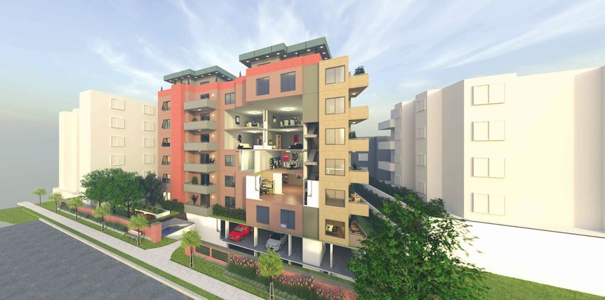
Our innovative afs logicwall® fibre cement, and afs rediwall® pvc permanent formwork walling systems have
enabled the speedy and cost-efficient installation of load-bearing walls across a range of projects including multi-
residential, hotels, aged care facilities, shopping centres and student accommodation.
No matter what the application from the basement right through to the penthouse, we have a comprehensive
walling solution to meet the demands of any project as only AFS is able to offer you the versatility of both a fibre
cement or pvc walling solution.
Our rediwall® pvc system’s extruded components simply snap or slide together to create a concrete formwork
erected with maximum efficiency. Rediwall® requires almost no machinery-aided installation. In fact, installations
can be undertaken without the need for any detailed training. And with its high quality semi-gloss finish it requires
no additional finishing for most applications.
Suitable as a tough load bearing solution for building subterranean structures such as basements and retention
tanks, it can also be utilized for above ground applications such as party walls, columns and retaining walls,
making it a truly versatile solution.
Backed by one of Australia’s most trusted brands
AFS Systems is a division of CSR Building Products Limited, one of Australia's
leading building products companies.
We form part of CSR's portfolio of trusted brands - amongst some of the biggest
names in the Australasian building products industry.
2019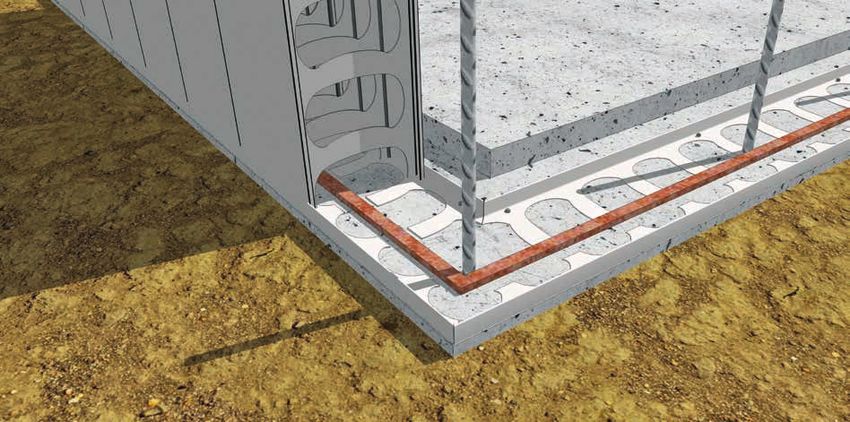
5
SYSTEM OVERVIEW
AFS Rediwall® systems provide loadbearing wall            systems are highly modular, providing architects and
solutions for residential or commercial structures and    engineers the freedom to design buildings to suit
multi storey buildings. These systems can be used for     various applications.
both above and below ground structures. The rediwall®

      Up to 7.5m height
      (continuous profile)
      loadbearing walls                                                                                Slab-to-slab
                                                                                                       multi storey
                                                                                                       loadbearing
                                                                                                       walls

                                                         Lintels

                                                                                                             Balustrades
                                                          Sills

                                 Door &                                           Floor/slab/
                                 Window                                           landing/stair
                                 openings                                         engagement

                                                                                                                    Blade
                                                                                                                    Wall

                                                                                                                PVC faces
                                                                                                                require no
                                                                                                                finishing
                                                    Optional board
                                                    lining of walls on
                                                    batten framing

                                                                   Below ground
                                                                   basement/
                                                                   sub floor
                                                                   construction
                                                                                  Note: If rediwall® is exposed to UV,
                                                                                  appropriate protective finish shall be applied.

2019 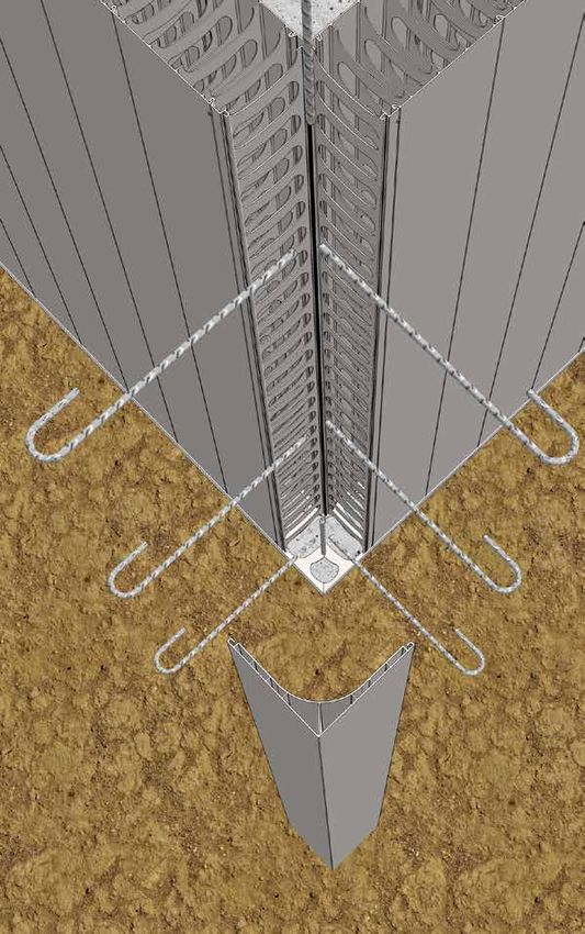
6
    Rediwall®
    Party walls

    Rediwall®
    Boundary walls

    Rediwall®
    Corridor walls

    Rediwall®
    Balustrades

Rediwall®
Garden/Landscape
walls
Rediwall®
Retention Tanks

    Rediwall®
    Basement walls

                     2019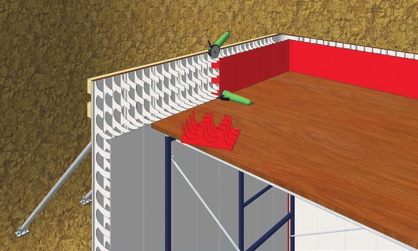
7
         Rediwall®
         Façade walls

         Rediwall®
         Balustrades

         Rediwall®
         Blade walls

         Rediwall®
         Lift & Stair shafts

             Rediwall®
             Retaining walls

         Rediwall®
         Blade walls

2019 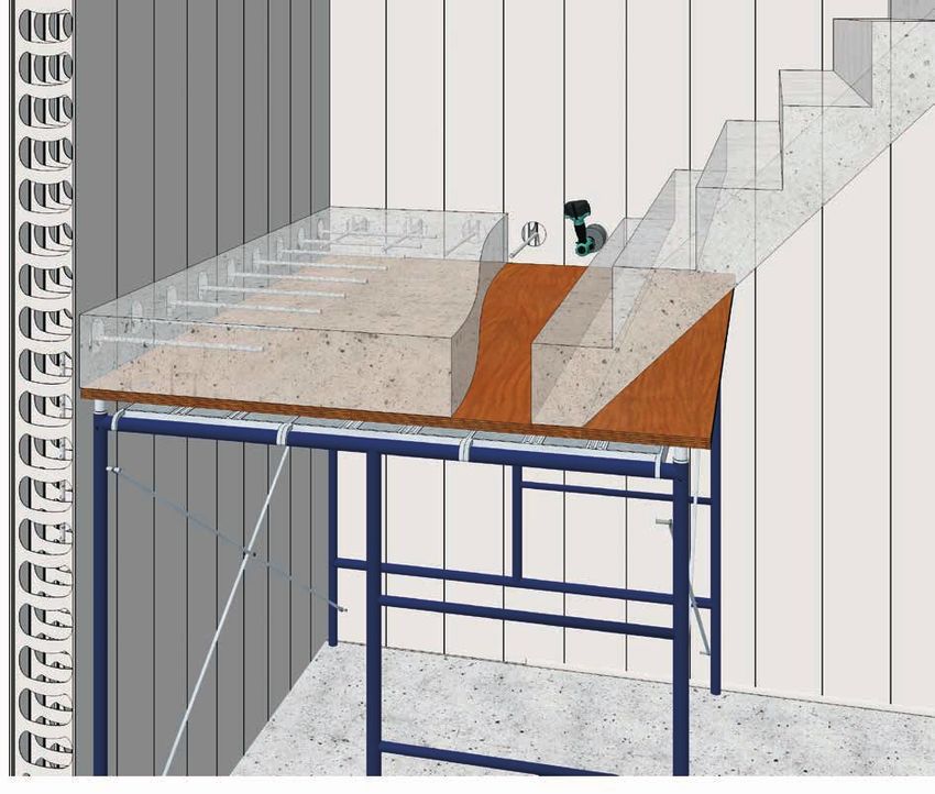
8
Rediwall® Product Description
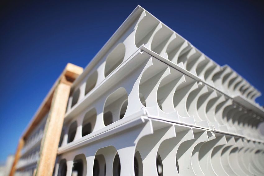
Rediwall® consists of extruded rigid PVC components that serve as a permanent formwork for cast in-situ
concrete walls for a large range of applications. The extruded components slide and snap together to create
a PVC formwork that remains in place after the concrete is poured and cured, providing a low maintenance,
finished wall surface.
The AFS Rediwall® system allows for the panels to be installed from the concrete slab which accommodates the
vertical walls being built prior to the horizontal formwork being installed
The available rediwall® types are identified in the following table:
TABLE A1: Rediwall® Systems Overview
OVERALL CONCRETE PVC WALL
CORE FILLED MASS UNFILLED MASS
AFS Rediwall® THICKNESS THICKNESS
(INTERNAL (kg/m2) (kg/m2)
(NOMINAL) CAVITY) (mm)
RW110C 110mm 105mm 260 11.18 2.4
Clip System RW156C 156mm 151mm 375 11.12 2.4
RW200C 200mm 195mm 480 12.49 2.4
Slide System RW256S 256mm 251mm 620 17.12 2.4
Rediwall® System Benefits
With an increasing demand throughout the construction industry for faster and more efficient building methods,
rediwall® has gained rapid acceptance in the market place due to the range of benefits it offers developers,
designers and builders, including:
• Cost efficiency
• Speed of construction
• Ease of installation and materials handling
• Low maintenance and aesthetically appealing finish
• NCC compliant
• Water resistant
• Design versatility
2019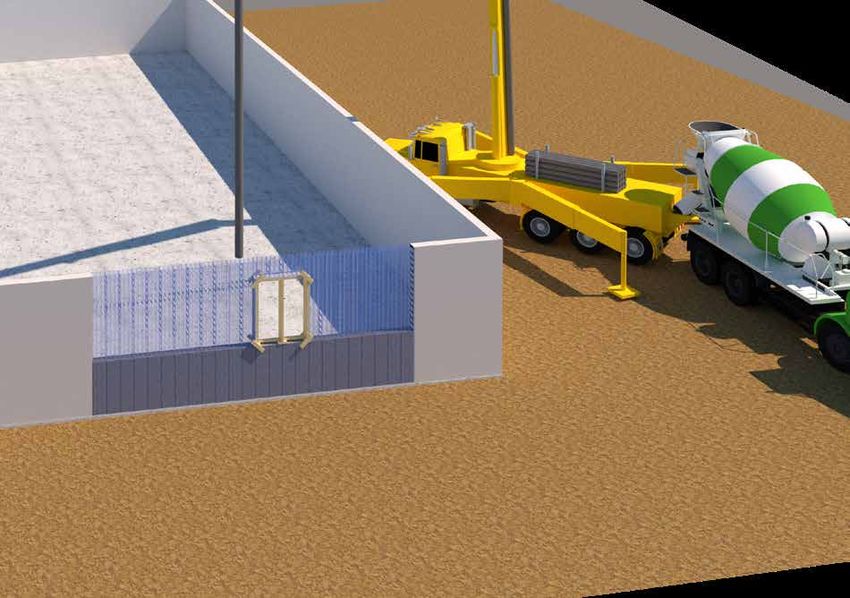
9
COMPONENTS, TOOLS & ACCESSORIES

Components for RW110C System

                   RW110C Panel                                                        Description

                                                 Male

                                                                            An extruded PVC panel
                                                             66.6mm         used to form the main body
                                                                            of a wall. Adjoining panels
                                                                            are fitted using the male to
                                 250mm                       66.6mm 259mm
                                                                            female clip-in system. Each
                                                                            panel is extruded to a surface
                                                                            tolerance of 1.5mm. Has 4
                                                                            internal webs with oval holes
                                                             66.6mm         for single reo bar placement.
                                                                            For m2 calculation, face width
                                                             27.4mm         is 250mm.
                                                Female

                                                110mm

               RW110C Corner Assembly                                                  Description
                                                  135mm                     A three piece PVC panel
                                                                            that forms a corner between
                                                                            walls meeting at 90º.
                                                                            Designed to allow for removal
                                                                   110mm    of the outside 90º corner
                                   135mm
                                                                            cap for easy placement
                                                                            and inspection of internal
                                                                            reinforcement. Cap is refitted
                                                                            for concrete filling. Adjoining
                                                                            panels are fitted using the
                                                 110mm                      male to female clip-in system.

                     Floor Track                                                       Description

                                                                            A PVC track used to set the
                                                                            bottom line of the wall. Laid
                                         30mm                               flat, the floor track has large
                                                                            holes for starter bars, etc. The
                                                         117mm              sides are for both locating the
                                                                            panels and for screw fixing to
                                                                            the bottom of the panels.

                      T joiner                                                         Description

                                                                            A PVC extrusion used to start
                                                                            a T-wall from a through wall,
                                                                            where the T-wall is close to
                                                                            90º. Fixed vertically to the face
                                    12mm                                    of the through wall. Has holes
                                                                            in its face to assist alignment
                                                           110mm            when drilling the through
                                                                            wall for reo bar placement.
                                                                            Adjoining panels are fitted
                                                                            using the male to female clip-
                                                                            in system.

2019 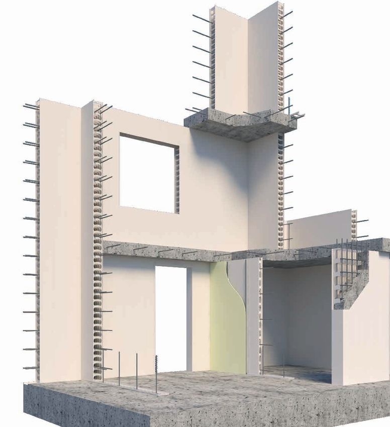
10
          H joiner                                            Description

                                                   A slide-on PVC extrusion.

                                                   Primarily used horizontally on
                                                   external walls where it is laid
                                                   along the straightened top
                          100mm                    of panels to act as a bottom
                                                   track for the next level of
                                                   panels.

                                                   Also used vertically as a wall
                                     117mm
                                                   make-up piece. Can be slid
                                                   into a gap in the wall of 50mm
                                                   or less and screw fixed to
                                                   adjoining panels.

     Slide on End Cap                                         Description

                                                   A slide-on PVC extrusion for
                                                   capping off wall ends and
                          30mm                     openings. Fixed on each side
                                                   with screws and/or glue. Can
                                     117mm         be installed before or after
                                                   wall is filled. Adequate bracing
                                                   must be provided.

     Fibre Cement Strip                                       Description

                                                   A fibre cement strip, for
                                                   closing off wall ends, where
                                                   a simple shutter is required.
                                                   Cut to length on-site, the strip
                                             9mm
                                                   slides in behind the female
                             103mm                 clip end of the panel (or
                                                   alternatively behind a web).
                                                   Can also be use as a pour
                                                   break. Adequate bracing must
                                                   be provided.

                          2019
11
Components for RW156C System
RW156C Panel Description
156mm
An extruded PVC panel
Male
used to form the main body
27.4mm
of a wall. Adjoining panels
66.6mm
are fitted using the male to
female clip-in system. Each
259mm panel is extruded to a surface
250mm 66.6mm tolerance of 1.5mm. Has 4
internal webs with oval holes
for single reo bar placement.
66.6mm
For m2 calculation, face width
is 250mm.
Female
RW156C Corner Assembly Description
170mm A three piece PVC panel
that forms a corner between
walls meeting at 90º.
Designed to allow for removal
156mm of the outside 90º corner
170mm cap for easy placement
and inspection of internal
reinforcement. Cap is refitted
for concrete filling. Adjoining
170mm panels are fitted using the
male to female clip-in system.
115mm Spacer Description
An extruded PVC panel used
to adjust the length of a wall.
Adjoining panels are fitted
115mm 66.6mm using the male to female
clip-in system. Used primarily
close to the closure of a wall,
Has 2 internal webs with
156mm oval holes for single reo bar
placement. For m2 calculation,
face width is 115mm.
Floor Track Description
A PVC track used to set the
bottom line of the wall. Laid
30mm
flat, the floor track has large
holes for starter bars, etc. The
sides are for both locating the
163mm panels and for screw fixing to
the bottom of the panels.
2019 12
Female/Female Joiner Description
An extruded PVC joiner used
42mm to reverse a male panel end
to a female panel end. For
156mm m2 calculation, face width is
42mm.
J Track Description
A slide-on PVC extrusion
primarily used horizontally on
50mm external walls where an edge-
100mm form slab is to be formed. It
is laid along the straightened
top of panels to act as a
164mm
bottom track for the next level
of panels and to assist with
edge-form preparation.
H Joiner Description
A slide-on PVC extrusion
primarily used horizontally on
external walls where it is laid
along the straightened top
of panels to act as a bottom
100mm track for the next level of
panels.
164mm Also used vertically as a wall
make-up piece. Can be slid
into a gap in the wall of 50mm
or less and screw fixed to
adjoining panels.
T Joiner Description
A PVC extrusion that is fixed
vertically to the face of a
through wall to start a T-wall,
where the T-wall is close to
12mm 90º. Has holes in its face to
156mm assist alignment when drilling
the through wall for reo bar
placement. Adjoining panels
are fitted using the male to
female clip-in system.
201913
Slide on End Cap Description
A slide-on PVC extrusion for
capping off wall ends and
30mm openings. Fixed on each side
with screws and/or glue. Can
163mm be installed before or after
wall is filled. Adequate bracing
must be provided.
Fibre Cement Strip Description
A fibre cement strip, for
closing off wall ends, where
a simple shutter is required.
Cut to length on-site, the strip
9mm
slides in behind the female clip
149mm end of the panel or joiner (or
alternatively behind a web).
Can also be use as a pour
break. Adequate bracing must
be provided.
2019 14
Components for RW200C System
RW200C Panel Description
An extruded PVC panel
200mm used to form the main body
of a wall. Adjoining panels
Male are fitted using the male to
27.4mm
female clip-in system. Each
66.6mm panel is extruded to a surface
tolerance of 1.5mm. Webs
250mm 66.6mm 259mm
have kidney shaped holes
for single, or double reo bar
placement by inverting the
66.6mm panel. Holes must be kept
22.8mm in horizontal alignment. For
Female m2 calculation, face width is
250mm.
Corner Assembly Description
215mm
A three piece PVC panel
that forms a corner between
walls meeting at 90º.
Designed to allow for removal
of the outside 90º corner
215mm 200mm cap for easy placement
and inspection of internal
reinforcement. Cap is refitted
for concrete filling. Adjoining
200mm
panels are fitted using the
male to female clip-in system.
115mm Spacer Description
An extruded PVC panel
used to adjust the length
of a wall. Adjoining panels
are fitted using the male to
female clip-in system. Used
66.6mm 115mm
primarily close to the closure
of a wall. Has 2 internal webs
with kidney shaped holes
200mm for single, or double reo bar
placement by inverting the
panel. For m2 calculation, face
width is 115mm.
Floor Track Description
A PVC track used to set the
bottom line of the wall. Laid
30mm flat, the floor track has large
holes for starter bars, etc. The
207mm sides are for both locating the
panels and for screw fixing to
the bottom of the panels.
201915
Female/Female Joiner Description
An extruded PVC joiner used
42mm to reverse a male panel end
to a female panel end. For
200mm m2 calculation, face width is
42mm.
J Track Description
A slide-on PVC extrusion
primarily used horizontally on
external walls where an edge-
100mm form slab is to be formed. It
is laid along the straightened
top of panels to act as a
208mm bottom track for the next level
of panels and to assist with
edge-form preparation.
H Joiner Description
A slide-on PVC extrusion.
Primarily used horizontally on
external walls where it is laid
along the straightened top
of panels to act as a bottom
100mm track for the next level of
panels.
207mm Also used vertically as a wall
make-up piece. Can be slid
into a gap in the wall of 50mm
or less and screw fixed to
adjoining panels.
T Joiner Description
A PVC extrusion that is fixed
vertically to the face of a
through wall to start a T-wall,
12mm
where the T-wall is close to
90º. Has holes in its face to
200mm assist alignment when drilling
the through wall for reo bar
placement. Adjoining panels
are fitted using the male to
female clip-in system.
2019 16
Slide on End Cap Description
For capping off wall ends
and openings. A slide on
30mm
connection with a 40mm
side for fixing with screws or
glue. Can be installed before
207mm
or after wall is filled. Must be
propped when filling, if a flat
end is required.
Fibre Cement Strip Description
A fibre cement strip, for
closing off wall ends, where
a simple shutter is required.
Cut to length on-site, the strip
9mm slides in behind the female clip
193mm end of the panel or joiner (or
alternatively behind a web).
Can also be use as a pour
break. Adequate bracing must
be provided.
201917
Components for RW256S System
RW256S Panel Description
An extruded PVC panel used
to form the main body of a
wall. Adjoining panels are
fitted using the male to female
slide in coupling system. Each
150mm panel is extruded to a surface
73.5mm
tolerance of 1.5mm. Webs
have arched rectangular holes
to accept double reo with
256mm
appropriate concrete cover.
Panels are joined by male to
female slide in coupling. For
m2 calculation, face width is
150mm.
Floor Track Description
A PVC track used to set the
bottom line of the wall. Laid
30mm flat, the floor track has large
holes for starter bars, etc. The
264mm sides are for both locating the
panels and for screw fixing to
the bottom of the panels.
Female/Female Joiner Description
An extruded PVC joiner used
to reverse a male panel end
42mm
to a female panel end. For
m2 calculation, face width is
256mm 42mm.
Quick Cap Description
A slide-on PVC extrusion for
capping off wall ends and
256mm openings. Adequate bracing
must be provided.
22mm
Slide On End Cap Description
A slide-on PVC extrusion for
30mm capping off wall ends and
openings. Adequate bracing
264mm must be provided.
Fibre Cement Strip Description
A fibre cement strip, for
closing off wall ends, where
248mm
a simple shutter is required.
Cut to length on-site, the strip
9mm slides in behind the web of an
end panel. Can also be use
as a pour break. Adequate
bracing must be provided.
2019 18
Tools & Accessories
Screws Description
Button head stitching screw
10G x 25mm, for joining of
rediwall® components.
Wall Brace Description
Adjustable wall bracing
is available from AFS for
purchase. Contact afs for
further information.
Squint Angle Description
Powder coated metal squint
angle 150 x 150mm at 135º
Used to form 45º wall corners.
Floor Angle Description
Galvanised metal floor angle
50 x 50mm at 90º.
Used to set the bottom line of
the wall. Laid flat, and set at
a distance apart to match the
wall sized used. The sides are
for both locating the panels
and for screw fixing to the
bottom of the panels
201919
Workplace Health Safety and the Environment
AFS rediwall® has been designed with workplace health safety and the environment in mind. Issues regarding
installation have been considered so that the risk of harm to those who build, use and maintain the structure is
minimised.
A vital consideration when planning installation, is to have appropriate safe systems of work to identify hazards,
assess risks, control risks and to ensure a process to review control measures.
Assessing the hazards associated with the installation methods, equipment, chemicals, tools, trades, and work
environment is the responsibility of both the builder and installer.
Appropriate assessment of risk, adequate resources, communication methods and training provided to workers
is to be considered and documented for each site location.
AFS has documented sample safe work methods that can be accessed upon request as REFERENCE
MATERIAL ONLY. This can be provided as an aid to builders and installers when risk assessing the work, and
when developing documentation.
Consultation and training of workers in agreed safe methods will always be the builders and installers responsibility.
For further information please visit SafeWork Australia https://www.safeworkaustralia.gov.au/risk
Personal Protective Equipment
The Personal Protective Equipment required may
vary from site to site and from time to time, and it
is the responsibilty of every individual to ensure that
they use the appropriate equipment to safeguard
themselves and those around them.
A basic protective kit should include, but not
necessarily be limited to:
• Dust mask
• Safety gloves
• Hearing protection
• Sunscreen cream/lotion
• Eye protection
2019 20
Hand Tools Required
To safely and efficiently complete any task, it is essential to have the necessary tools available and to use the right
tool for the right task.
A typical range of hand tools would include, but not be limited to the following:
• Tool bag/belts
• Cutting knife
• Handsaws
• Hammers - ‘claw’ and ‘gympie’
• Pencils, marking pens, chalk
• Variety of pliers
• A range of squares
• String and chalk lines
• Tape Measures – eg. 8m and 3m
• Spirit levels – range of lengths
eg. 600mm and 2000mm
• Plumb Bob
• Laser leveling equipment
Access Tools
All scaffolding and safe access provisions are the responsibility of the builder and installers and are governed
by the individual site conditions. It is essential that safe work practices and all associated standards are met/
complied with. Installers would normally provide a range of platforms for personal access to the top of wall panels
for the fitting of braces and checking of stringlines.
201921
Power Tools
There are a range of power tools required during installation of afs rediwall®. Wherever possible preference
should be given to cordless tools.
Note: All power tools require tagging as per site requirements.
Suggested power tools and applications include:
• A ‘charge gun', such as the ‘Hilti
Hilti GX120
GX120’ with appropriate fixings to pin
the floor track to the concrete slab.
• A screw driver gun, with appropriate
driver bits and screws for fixing
rediwall® panels to track and adjacent
panels or form deck. Also used to
fixing bracing.
• A range of grinders and circular saws
for cutting components and timbers for
bracing.
Concrete Pouring & Finishing Tools
• Concrete pouring and finishing tools,
including:
– At least one wheelbarrow, multiple shovels
and a range of trowels.
– Concrete vibrator: 40mm diameter
maximum.
2019 22
THE CONSTRUCTION PROCESS
Construction Process Overview
➊ Place Order
Sample Rediwall® Order Form
Order Formv1
Call 1300 727 237 or email: afsorders@csr.com.au
ABN: Order number: Date:
Company name: Delivery address:
Client completes rediwall® order form, listing lineal Email:
Site contact: Phone:
Delivery date:
Delivery: £ Pickup from AFS, Minto or delivery via
Time:
£ Semi £ Rigid £ Rigid/crane
RW 110C
metres of each wall height required, and selecting any
Page of
AFS will price on receipt of your entries in metres/height Additional to your m2 pricing
Speedy-Snap-InTM Wall Panels Tick your RW size Floortrack End Caps
Lineal Metres Height (m) Lineal Metres Height (m)
Floortrack is included in your m2 Quantity
unless: (tick choice)
accessories required. The completed order form is
110mm £ x 2.8m 110mm £ x 2.8m
£ x 3.2m £ x 3.2m 110mm x 2.8m
£ Yes, floortrack required
110mm £ x 2.8m 110mm £ x 2.8m £ No floortrack required
£ x 3.2m £ x 3.2m 110mm x 3.2m
Metres of floortrack additional
£ x 2.8m 110mm £ x 2.8m
110mm to that included in your m2?
£ x 3.2m £ x 3.2m
Sample
submitted to afsorders@csr.com.au electronically or
110mm £ x 2.8m 110mm £ x 2.8m 110mm
£ x 3.2m £ x 3.2m
Ezy-FitTM 90º Corners Tick your RW size Tick choice:
Quantity Quantity
£ PVC floortrack £ Floor angle
by fax on 1300 715 237.
110mm £ x 2.8m 110mm £ x 2.8m
£ x 3.2m £ x 3.2m Screws 25mm screws • 1,000 per box Waterstop
110mm £ x 2.8m 110mm £ x 2.8m How many boxes?
£ x 3.2m £ x 3.2m How many metres?
$12 per lineal metre
H-Joiner Tick your RW size £ No screws required Tick to select
Quantity Quantity
£ x 2.8m £ x 2.8m Fibre Cement Strip Braces
110mm 110mm
£ x 3.2m £ x 3.2m
Quantity Braces charged on delivery at $60 (each)
Introducing the rediwall® ordering
and credited at $40 (each) upon return
110mm £ x 2.8m 110mm
£ x 2.8m
£ x 3.2m £ x 3.2m 110mm x 3m
Quantity x 3m
Included in your m2 pricing
Squint Angles For non-90° corners
Upon receipt we will contact you to confirm this order
Quantity x 3m
AFS office use only:
Total m
app... an easier way to order.
T-Joiner Tick your RW size 2
Quantity Quantity
110mm £ x 2.8m 110mm
£ x 2.8m Extras
£ x 3.2m £ x 3.2m
For fast, convenient ordering why not place your order All prices exclude GST. Lead times from confirmation of your order: an AFS customer service representative will confirm lead times for your order. A surcharge may apply for orders under 125m2
via the rediwall® ordering app. Just a few quick taps
and/or for crane truck delivery. AFS will not accept return of left-over product that has been approved and signed for by the customer. AFS Standard Terms & Conditions of Sale apply to this order
(copy available upon request). Quantity of floortrack ordered over and above the lineal metres (L/M) of wall panel ordered will be charged out @ $8.50/LM.
Questions? Call us on 1300 727 237 or email afsorders @ csr.com.au
ABN 45 576 072 788
tells us what you want and where you want it, an easier
hassle-free way to place your order anytime from
anywhere.
To access the rediwall® app simply download it from
the App Store. (Android version coming).
Once you've downloaded the App you'll be asked to
input your account name and number as a one-off
registration.
Should you need assistance with obtaining your
account number, please call our customer service
team on 1300 727 237
➋ Production
AFS Rediwall® is manufactured in a state of the art
factory with precision processes, manufacturing large
volumes of quality product with short lead times.
➌ Delivery
AFS’s in house transportation and logistics team
ensure that orders are shipped with care, arriving on
site in a timely manner. Panels are shipped in packs
of up to approximately 20 panels for RW110C, 20 for
156C, 20 for RW200C and 24 for RW256S, which are
easily delivered to site and craned onto the floor slab
or deck ready for placement.
201923
Construction Process Overview – Continued
➍ Site Erection
Once set-out is complete, rediwall® floor track is
installed, followed by the rediwall® panels being lifted
into place by hand over the reinforcement starter bars.
In some cases it is simply installed off the formwork
deck of the next floor level. The panels are then braced
using temporary bracing or fixed to the formwork deck.
➎ Openings & Services
Smaller penetrations may be cut out once the
formwork is installed and then capped off using the
rediwall® End Cap. Doorway and window openings
are formed using sill and lintel panels which can be
supplied cut to size. Steel door frames can be installed
to suit, or the openings can simply be capped off using
the rediwall® End Cap.
➏ Concrete Core Fill
The erected panels are then core filled with concrete
using a mix design that is suitable for filling rediwall®,
via a concrete pump. This is mostly done from the
formed deck of the next slab or off a scaffold. Refer to
concrete core fill procedure.
2019 24
Construction Process Overview – Continued
➐ Finishing of Walls
Once the concrete core fill has gained strength and the
walls are permanently braced by the floor or roof structure
at the top of the walls, the temporary bracing is removed.
The smooth, off white finish of the rediwall® panels is a
suitable finish for many applications, refer to Volume 2 –
"Wall Construction Detailing & Finishing Treatments Guide"
for specific finishes for rediwall®.
Suitable paints or renders can be applied to the surface
if required. Please contact Dulux Acratex, Rockcote
or equivalent render suppliers, for their warranted
specifications on the rediwall® substrate.
201925
Ordering
Ordering of rediwall® is a simple process requiring construction drawings, are inserted into the rediwall®
a rediwall® Order Form to be completed by the order form along with the quantities of accessories,
appropriate project personnel and submitted to the such as: corners, end caps, floor track and H-sections.
rediwall® production team.
To avoid delays during erection, it is recommended
A sample of the form is shown below. An that additional rediwall® components are ordered.
interactive PDF form can be downloaded from Additional quantities ordered should be based on
w w w. a f s f o r m w o r k . c o m . a u / r e d i w a l l - o r d e r- project size, construction schedule, site proximity to
form completed digitally and then emailed to – the rediwall® supply facility, the potential for damage
afsorders@csr.com.au on site and the potential for site modifications.
Alternatively a printable form can be downloaded On completion and submission of your order form you
at www.afsformwork.com.au/rediwall-order-form will receive a confirmation detailing exactly what has been
completed and returned by email as above or faxed to entered into the production system. It is the customers
1300 715 237. responsibility to check this confirmation for accuracy and
advise AFS of any errors immediately.
Lengths and heights of walls, derived from project
How to order Sample Rediwall® Order Form
Order Formv4
Complete your company details, make sure to
Call 1300 727 237 or email: afsorders@csr.com.au
➊
Sample
ABN: Order number: Date:
include the correct site contact details. Company name: Delivery address:
Email: Delivery date: Time:
Complete your order number, delivery address
Site contact: Phone: Delivery: £ Pickup from AFS, Minto or delivery via £ Semi £ Rigid £ Rigid/crane
➋ and your requested delivery date. RW 110C Page
AFS will price on receipt of your entries in metres/height
Speedy-Snap-InTM Wall Panels Enter your RW size
of
Floor Track
Additional to your m2 pricing
End Caps
Calculate the total linear metres required and the
➌
Lineal Metres Height (m) Lineal Metres Height (m)
Floor track is included in your m2 Quantity
110mm 110mm unless: (tick choice)
110mm x 2.8m
£ Yes, floor track required
height of the panels you require. All accessories 110mm 110mm £ No floor track required
110mm x 3.2m
Metres of floor track additional
are supplied at stock length. 110mm 110mm to that included in your m2?
Screws 25mm screws • 1,000 per box
110mm 110mm 110mm
Add quantities of Squint Angles and T junctions
How many boxes?
➍
Ezy-Fit TM
90º Corners Tick your RW size Tick choice:
Quantity Quantity
£ PVC floor track £ Floor angle £ No screws required Tick to select
if required. 110mm £ x 2.8m
£ x 3.2m
110mm £ x 2.8m
£ x 3.2m Fibre Cement Strip Braces
£ x 2.8m £ x 2.8m Quantity Braces charged on delivery at $60 (each)
110mm 110mm and credited at $40 (each) upon return
£ x 3.2m £ x 3.2m
Select your floor track option and quantity. x 3m
110mm
➎ H-Joiners Tick your RW size Quantity x 3m
Quantity Quantity
110mm £ x 2.8m £ x 2.8m
110mm
£ x 3.2m £ x 3.2m Upon receipt we will contact you to confirm this order
110mm £ x 2.8m 110mm
£ x 2.8m
£ x 3.2m £ x 3.2m AFS office use only:
Enter the quantity of end caps, screws, braces
➏
Included in your m2 pricing Total m2
and fibre cement strips you will need.
Squint Angles For non-90° corners
Extras
Quantity x 3m
T-Joiners
Submit your form and AFS will contact you for
➐
Quantity
110mm x 3.2m
order confirmation before processing your order.
Check the confirmation email from AFS for accuracy.
Introducing the rediwall® ordering All prices exclude GST. Lead times from confirmation of your order: an AFS customer service representative will confirm lead times for your order. A surcharge may apply for orders under 125m2
app... an easier way to order.
and/or for crane truck delivery. AFS will not accept return of left-over product that has been approved and signed for by the customer. AFS Standard Terms & Conditions of Sale apply to this order
(copy available upon request). Quantity of floortrack ordered over and above the lineal metres (L/M) of wall panel ordered will be charged out @ $8.50/LM.
Questions? Call us on 1300 727 237 or email afsorders @ csr.com.au
ABN 45 576 072 788
For fast, convenient ordering
why not place your order To access the rediwall® app simply download it from
via the rediwall® ordering the App Store. (Android version coming).
app. Just a few quick taps
Once you've downloaded the App you'll be asked to
tells us what you want and
input your account name and number as a one-off
where you want it, an easier
registration.
hassle-free way to place your
order anytime from anywhere. Should you need assistance with obtaining your
account number, please call our customer service
team on 1300 727 237
2019 26
CONSTRUCTION AND INSTALLATION
PROCEDURES
This Installation Procedure Section has been prepared • Floor track/floor angle installation
by AFS Systems Pty Ltd to assist builders, engineers • Installation of 90° corner
and architects to understand the construction
• Screw fixing of panels to floor track
procedures for loadbearing and retaining walls using
rediwall®. • Installation of corner reinforcement
• Horizontal reinforcement placement
The Installation Section provides information on the
• Vertical reinforcement placement
following aspects of construction using rediwall®:
• End caps
• Ordering • Curved walls
• Delivery • Tanking
• Wall set-out • Bracing
• Establishing installation starting point
Introduction
Although every effort has been made to ensure that Rediwall® consists of extruded rigid polymer
all the information provided in this Installation manual components that serve as a permanent formwork for
is factual and consistent with good practice, AFS concrete walls in loadbearing and retaining applications.
does not assume any liability for errors or oversights Popular uses include basement walls, retaining walls,
resulting from the use of information contained in this retention tanks, foundation and landscaping walls,
manual. blade walls etc. The extruded components connect
together to create formwork that remains in place after
AFS highly recommends that the entire construction the concrete is poured and cured. This combination
team are fully aware of the construction order and results in a strong concrete core wall with a low
methods prior to commencement of wall installation. maintenance, finished wall surface.
Four rediwall® systems are available as shown in
TABLE B1.
TABLE B1: Rediwall® Systems Overview
WALL THICKNESS
Rediwall® SYSTEM
OVERALL (NOMINAL) CONCRETE CORE
RW110C 110mm 105mm
RW156C 156mm 151mm
RW200C 200mm 195mm
RW256S 256mm 251mm
Note: Concrete core thickness is calculated including manufacturing tolerance.
201927
Component Delivery & Worksite Layout
Transport to site is typically arranged by AFS. Rediwall® Rediwall® panels from 600mm to 7.5m can be
packs are unloaded by a crane or forklift (provided supplied at the requested custom heights, suited to
by the builder), or crane truck (if requested at point the specific project requirements and are listed on the
of sale). Customers can also pick up with their own delivery docket received with each delivery.
transport if prearranged. On delivery of the rediwall®
components, place the packs strategically around Using the pins/markings provided by the surveyor
the area where it is to be installed to minimise manual and the construction drawings, ensure the walls are
handling. Placement of packs should not interfere with clearly and accurately set-out. The builder should be
locations for temporary wall bracing required during responsible for this and should sign off on the set-out
construction. prior to commencement.
2019 28
Floor/Wall Junction – Floor Track Installation
Introduction 2. The bottom restraining member may also act as
formwork to cover any gaps at the underside of the
Attention must be paid to the specified detailing of the wall due to irregularities in the surface of the footing
horizontal slab/wall joint. Some projects have specific or slab.
waterproofing requirements, such as installation of
expandable Waterstop at the slab to wall junction. 3. The bottom restraining member is to be fixed to the
rediwall® components and anchored to the foundation
WARNING: Rediwall® panels cannot be moved as required by the Project Engineer's specifications.
without demolition once filled with concrete.
4. Bottom restraining members fitted on one side of
the wall are to be connected to the wall at 500mm
Base Restraint maximum centres. For walls over 5m in height, the
connection to the wall is to be at 250mm maximum
1. A continuous horizontal member is required at the centres.
base of the wall on at least one side of the rediwall®
panels to hold the members straight and to prevent
movement during core filling. This member is typically
PVC floor track, however 40 x 40mm PVC angle
installed on one side of the wall is acceptable.
Rediwall® PVC Floor Track
Starter bars should be set into the concrete as per engineering specifications.
➊ Corner bars should be set in the middle of the rediwall® corner profile.
Mitre the ends
➋ of the floor track
so that the corner joins
neatly.
Tw o b e a d s o f
➌ polyurethane
sealant or as per
waterproofers details, ➊
must be applied in
accordance with
the manufacturer's
instructions under the
rediwall® floor track (one
on each side of the track) ➌ ➍
on all external walls, and
any portion of a wall that
separates or adjoins a
➋
wet area (e.g. bathroom, kitchen, or laundry).
Rediwall® floor track is then placed in the required location and fixed to the
➍ concrete footing or slab using a masonry fixing gun or drill and anchor masonry
fixing system. Fix with fasteners each side of the track at 500mm centres for walls up
to 5m height, or at 250mm maximum centres for walls over 5m height.
201929
Water Treatment of Cold Joints
All waterproofing details are to be completed by the Any required waterproofing products must be installed
Project Builder and waterproofing contractor. When strictly in accordance with the particular manufacturer's
filled with concrete, rediwall® is a water resistant wall instructions.
system. However specific areas requiring waterproofing
details include horizontal concrete cold joints, and
where water can track down along panel joints.
Install afs rediwall® floor track as per the standard
➊ installation instructions.
➋ Use an angle grinder to cut the floor track and
remove the centre web. To create a continuous
➊
clear path for the waterstop.
➋
Install waterstop to manufacturer's
➌ instructions, maintaining a continuous
seal. Refer to the project building designer
for details on waterstop performance and
installation requirements. ➌
Install rediwall® panels over the water
➍ stop and fix to the floor track. Ensure
that the panels DO NOT interfere with the
waterstop.
➍
2019 30
Control Joints
Movement Joints and
Crack Control Joints
Rediwall® when completed as a structural reinforced
concrete wall effectively had control joints at each web ➌
so no additional crack control joints are necessary.
Full depth "movement joints", when required, should
be installed at construction stage by the rediwall ➋ ➋
installer. Refer to engineer's details for control joint
locations.
Install afs rediwall® Female to Female joiner if
➊ required. ➊ ➌
Slide Fibre Cement Strips down behind the
➋ female joiner end of the panel. Provide bracing
across the joint with horizontal top hat brace as per the
standard bracing details.
Once core fill has cured install a backing rod and
➌ fill the gap with a fire rated sealant, as per the
sealant manufacturer's requirements.
NOTE: Optional doweling across the movement joint
for lateral restraint can be incorporated, if required by
engineer.
Starting Location
Introduction
It is important to consider the wall layout and to
establish the best starting point and sequence in which
to proceed with installation. This will help to ensure
that the working space is kept as clear as possible.
Consideration should also be given to the positioning
of bracing structures and minimising restriction of
movement around the site. Refer to the Bracing
section for details.
In the case of internal walls that are to be core filled off
a mobile scaffold, it is preferable to run the braces in a
way that leaves one face of each wall clear.
Once panel installation commences, consideration
must be given to the timely installation of horizontal
reinforcement.
WARNING
The individual components have a distinctive top and
bottom orientation, which must be maintained in order
for the web holes to be aligned. All panels are to be
installed so that web holes are aligned horizontally.
201931
Corner Construction
Corner Construction
Stand the corner assembly up and
➊ ➊ position on the floor track.
Install a wall panel either side of the
➋ corner assembly.
Screw fix the panels and the corner
➌ assembly to the floor tack.
➊
➋ ➋
➌
2019 32
Wall Construction
From your chosen starting location, hook
➊ one side of the rediwall® panel together
➊ making sure that the panel is above the slab
starter bars.
Swing the rediwall® panel around and
➋ snap the opposite side into the preceding
➋ profile.
Slide the assembly down over the starter
➌ bars.
To avoid movement of the rediwall® panels
➍ during concrete core filling, install one
screw each side of the panel through the floor
track at the joint location. Ensure appropriate
➌ screw fixings are used to secure the panels.
Walls constructed using angle floor track should
be fixed similarly.
Continue to install panels and accessories
➎ as required to complete the wall.
➍
➎
201933
Wall Reinforcement
Reinforcement bar placement
Once a sufficient section of wall has been assembled, reinforcement should be installed.
It is important that reinforcement is installed in a uniform manner and that the correct spacings are maintained.
This will help ensure correct concrete coverage.
Once the Rediwall® profiles are fixed in place,
➊ slide the horizontal reinforcement bars through
the holes. The shape of the cut hole will help hold the
bars in the correct position.
➊
➊
2019 34
Install the vertical reinforcement as per the project
➋ specification. 'Weave' the vertical bars either side ➌
Timber spacer fixed at
of the horizontal bars as shown. the top of the vertical
reinforcement
Secure the top of the bars with an LVL timber
➌ or similar to space and lock the bars in position.
➋
➋
Horizontal bars are
positioned on the
outside of the vertical
reinforcement
➋
2-3 bars are
positioned on the
inside of the
horizontal bars.
Typically at about
➋
1/3 or 1/4 of the wall
height up from the
bottom of the wall
Lower bars are
positioned on the ➋
outside of the vertical
reinforcement
➌
201935
Corner Reinforcement
Installation of Corner Reinforcing Bars
Care is to be taken when installing horizontal reinforcement in corner units as a ‘hook bar’ and ‘dropper’ system
is recommended.
Reinforcement must be placed in
accordance with the project Structural
Engineer's specifications
Install two or three rediwall ®
➊ panels on each side of the corner,
then insert the hook bar into the wall
and slide it into the corner. Repeat this
from the other side of the corner to form
a loop in the corner.
Align the ‘hook’ on each hook
➋ bar in the corner and insert the
vertical ‘dropper bar’ from the top of
the corner panel and through the loops
formed by the mating hook bars.
NOTE: Hook returns should be a
minimum of 150mm to prevent the
hook twisting in the cavity. (Panel
bracing not shown for clarity.)
➊ ➋
2019 36
Corner Reinforcement - alternate method
Installation of Corner
➋ Reinforcing Bars
When site access permits,
reinforcement bars may be installed
from the external wall side.
Reinforcement must be placed in
accordance with the project Structural
Engineer's specifications.
Remove the corner cap by sliding
➋ ➊ up and off the wall.
Align the ‘hook’ on each hook
➋ bar in the corner and insert the
vertical ‘dropper bar’ from the top of
the corner panel and through the loops
formed by the hook bars.
Replace the corner cap ready for core
filling.
Note: For short wall lengths, horizontal
reinforcing can also be installed
through the open corner.
➊
201937
Wall Construction
Full Height Panels
Install additional rediwall®
➊ panels by clipping each
panel into the previous one
and sliding it down into the
floor track. This procedure is
repeated to form a complete
wall.
➋ Plumb the wall section ➊
vertically, install bracing
and fix each panel to the floor ➊
track as construction proceeds.
Wall sections are formed
➋
➌ u s i n g f u l l re d i w a l l ®
panels. If a space of less then
250mm is left, spacers and
H Joiners installed vertically
can be used to make up the
➌
required distance. H Joiners
can be used vertically for a
gap of 50mm or less, screw
fixed both sides at 150 centres
to adjoining panels. Spacers
➋
are available in some systems,
refer to the components page
for availability.
WARNING
Refer to the Bracing section for detailed requirements and methodology.
2019 38
Safety Rail/Balustrade Wall Installation
Balustrade Wall
WARNING: Where rediwall® panels saw as per Structural Engineer's specifications and ensure that all
are to continue past a slab to form details (100mm maximum diameter). mandatory requirements are met.
a balustrade, care shall to be taken
Insert the required Note: Care should be taken when
when creating openings in the
rediwall® panel face to ensure that ➌ reinforcement steel as per the
Structural Engineer's details. When
core filling that no concrete loss
occurs due to the opening of the
the webs inside are not damaged
causing the panels to be weakened. filling these safety rail/balustrade panel face as this may create voids
walls, fill initially to the bottom of slab in the wall.
Install the rediwall® panels as level. Filling upper section shall be
➊ per the standard method. completed after the slab has been
poured.
Extra bracing may be required to
ensure panel stability during slab
Engagement of the wall and pour.
➋ slab can be achieved by
cutting holes in the rediwall® face
IMPORTANT: When being used as
Safety Rail it is up to the Project
to install reinforcing bars. Use a hole Engineer to determine the required
➊
➌
➋
201939
Steel Reinforcement Installation
Horizontal Reinforcement Installation
Horizontal reinforcement
➊ bars should be placed
into the wall when it reaches
a suitable length. Generally
the wall is slightly longer than
➊ the steel bar length. Slide the
reinforcement bar through the
rediwall® profile ensuring that
the bar will maintain the correct
overlap with the previous
and subsequent bars where
applicable.
Refer to the Project Engineer's
specifications for correct overlap
and spacing of reinforcing bars.
Note: When panels are installed,
ensure all webholes are aligned
horizontally. Damage to webs
inside can result in bulges when
wall is filled with concrete.
Vertical
Reinforcement
Installation
Vertical reinforcement bar
➋ should be placed vertically
➋ into the rediwall® profile, weaving
between alternate horizontal
bars. Ensure that the bar will
maintain the correct overlap with
the previous and subsequent
bars where applicable.
Refer to the Project Engineer's
specifications for correct overlap
and spacing of reinforcing bars.
2019 40
T Junction Construction
NOTE: Where a T-junction is to be formed, T-Joiner Track is
to be used for vertical alignment. T-Joiner Track is used when
core fill flow-through and reinforcement tie-in are required. If
joining a male panel end at junction, use floor track in lieu of
T-junction.
➊ Place the T-Joiner Track vertically up the wall and fix
➊ the T-Joiner Track to the existing rediwall® panels with
screws each side at 150mm vertical centres.
➋
Use a hole saw to cut the rediwall® panels to allow
➋ for concrete core fill flow and steel reinforcement
installation where appropriate. Refer to the Project
Engineer's specifications.
➌ Install the first
rediwall ® panel to
➎
the vertical T-Joiner Track
and ensure the clip edges
➍
lock securely each side of
the wall.
Once a suitable
➍ number of panels
have been installed, slide
the hook bars through the
tee wall and into the primary
wall, as per engineer's
➌ details.
Ensure hook bars are
➎ aligned and slide a
vertical dropper bar into the
primary wall and through
the hooked bars.
Bracing for T-junctions not
shown for clarity. Refer to
the Bracing section in this
guide for details.
201941
Obtuse Corner Construction
Cut the required angles from two
➊ standard panels.
Prepare floor track to accept obtuse
➋ angle panels. Mitre cut the floor tack
to make the required angle. Fix the floor track
as per earlier instructions in this guide.
➊ ➊ Install wall section up to the corner
➌ panels. Fix and brace.
Install the two cut panel pieces and
➍ screw fix to bottom track.
➍
➌
➋
2019 42
Screw fix appropriate
➎ galvanised steel angle
➎ squints at maximum 150mm
centres to both sides of the
internal and external corner
➎ junctions.
Continue with standard
➏ wall installation and wall
➎ bracing.
NOTE: Additional treatment may
be required for a waterproof
solution. Refer to the Project
Engineer for details. Galvanised
➎ squints angles are available for
45º corners only.
For angles other then 45º
➐ the corner joint must be
fully braced with PLY and LVL
timber.
➐
➏ ➐
2019You can also read