INTRODUCING AUTOCAD CHAPTER ONE - EXPLORING AUTOCAD'S INTERFACE WORKING WITH AUTOCAD FILES GETTING TO KNOW BASIC TOOLS DRAWING A ROUGH SKETCH
←
→
Page content transcription
If your browser does not render page correctly, please read the page content below
Chapter one
Introducing AutoCAD

   In this chapter:

   ►   Exploring AutoCAD’s interface
   ►   Working with AutoCAD files
   ►   Getting to know basic tools
   ►   Drawing a rough sketch
30       chapter one

                                          Introduction

                                          The way things were in the Elizabethan era, a director would have
                                          expected a set builder to produce a set by hand without any drawings.
                                          Over time, theatre has embraced the newest and most innovative
                                          technologies. It has progressed from candles to computerized lighting
                                          boards, from backstage Foley artists to surround sound, and from hand-
                                          operated fly systems to motorized fly systems. As a new approach to
                                          drafting, which has largely been done by hand, many theatres have begun
                                          to use computer-aided drafting (CAD, also commonly referred to as
                                          computer-aided design) software.
                                             Originally developed to lower costs and reduce the time needed to
                                          create complex prototypes, CAD software generates two- and three-
                                          dimensional graphics by processing geometric calculations. This helps
                                          designers from several industries prepare accurate drawings and
                                          specifications for production purposes. Industries that use CAD include
                                          engineering, manufacturing, architecture, interior design, and of course,
                                          entertainment.1
                                             For theatre, CAD can be used to generate accurate and detailed technical
                                          drawings for set designs, but it also has many additional benefits. For
                                          example, drafters who use CAD can work out calculations “on the fly,”
                                          reduce the time and energy needed for laborious drawing tasks, and make
                                          quick alterations to existing drawings. Furthermore, CAD drawing files
                                          can be easily emailed to theatres around the world, where they can be
                                          printed on demand.
                                             One of the most exciting aspects of CAD —and what really sets it apart
                                          from hand drafting—is that it allows the director and production team
                                          to virtually “walk through” the set in three dimensions to scrutinize,
                                          review, and modify it before it is built. It’s like having a digital version of a
                                          designer’s traditional maquette.
                                             In this book, we’ll introduce you to one of the more popular CAD
                                          applications, AutoCAD, to start you on your way to drafting accurate
                                          technical drawings for set designs. Now let’s get this show on the road!

                                          Downloading a Free Copy of AutoCAD

                                          If you are a student, you are probably working on a licensed educational
                                          version of AutoCAD at school. If you would like to work with AutoCAD
                                          on your home computer, you can obtain a free copy from the AutoDesk
                                          Education Community at the following link:

1 Yahoo Education Encyclopedia, s.v.
                                                  http://students.autodesk.com
  “computer-aided design,” accessed
  August 9, 2011,
  http://education.yahoo.com/reference/
  encyclopedia/entry/computerAD.
introducing autocad 31
Getting Started with the Set-Up Fig. 1.1
1
Though you’re probably eager to jump right in and start drawing, before
you start drafting in AutoCAD, you need to understand the basics of using
the application. Let’s have a look at AutoCAD’s interface, drawing files, and
some drawing commands. This will make it easier to understand the book
and communicate with other AutoCAD users. Now let’s get started.
Launching AutoCAD
Fig. 1.2
AutoCAD launches just like any other Windows application.
1) Double-click the AutoCAD 2011 - English shortcut (Fig. 1.1) on your
desktop.
Alternatively, launch the application through your computer’s start a
menu: Start > All Programs > Autodesk > AutoCAD 2011 > AutoCAD
2011 – English (Fig. 1.2a).
Your computer will make some noise and launch AutoCAD.
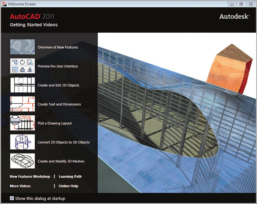
The Welcome Screen
When you launch AutoCAD 2011 for the first time after it is installed,
the Welcome Screen will be the first thing you see. It includes videos,
workshops, and other information to help you learn about AutoCAD 2011.
1) For now, uncheck the box next to Show this dialog at startup at * We won’t cover the Welcome
Fig. 1.3a. Screen in this manual, but any time
2) Close the Welcome Screen by clicking the X at Fig. 1.3b.* you would like to browse through
its demos and videos, simply open it
like this:
Fig. 1.3 1) Click the arrow for the Help
drop-down menu on the upper
b
right of the application at a:
2) Select Welcome Screen… (b).
a
b
a
32         chapter one

                                           The Application Window

                                           AutoCAD runs within the Windows operating system and opens as a
                                           window on your computer screen.2  This Application Window offers
                                           commands and options for AutoCAD drawing files.
                                              Have a look at the Application Window. The title bar is the row that runs
                                           across the top of the window (see also Fig. 1.12 on page 36). In the centre of
                                           the title bar, you’ll see AutoCAD 2011 - Drawing1.dwg, which is the name of
                                           the current document. On the left are the Application Menu and the Quick
                                           Access Toolbar. On the right are the InfoCenter and the buttons used to
                                           control the Application Window.
                                              As with all Windows applications, the AutoCAD window can be
                                           managed with the buttons in the top right corner of the title bar.
Fig. 1.4                                      Test out the Minimize, Restore, and Maximize buttons (Table 1.1) to
                                           see how they behave. Notice how the application is minimized to the
                                           Windows taskbar at the bottom of your computer screen (Figs. 1.4, 1.5). If
                                           you accidentally close AutoCAD, there’s no need to worry; you can easily
Windows Taskbar:
AutoCAD window                             relaunch it as shown earlier.
minimized

                                              Table 1.1. Window buttons

Fig. 1.5                                      Full screen window                     Floating window

Windows Taskbar:
AutoCAD window
floating or maximized
                                           Minimize:           Restore:              Maximize:            Close:
                                           Shrinks the         Reduces the           Increases the        Closes the
                                           Application         Application           Application          AutoCAD
                                           Window to the       Window to a           Window to full       application
                                           Windows taskbar     smaller floating      screen
                                           at the bottom of    size
Fig. 1.6                                   your computer
                                           screen

                                             Notice that when you click the Restore button, it becomes the Maximize
                                           button as the application switches to a floating window. In this state, the
                                           Application Window can be resized to suit your needs.

                                       a      1)   Move the mouse pointer to a corner or an edge of the Application
                                                   Window. The pointer will become a resize handle (Fig. 1.6a).
                                              2)   Press and drag the mouse to adjust the window to your liking.
2 Although there is a version of AutoCAD
  available for the Mac, this book will
  deal only with the Windows version.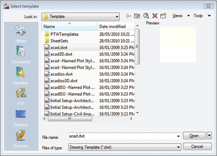
introducing autocad            33

    The Application Menu
                                                                                                                          1
    When you click the big red A at a in Fig. 1.7, the Application Menu will
    open. It contains common commands for managing files, most of which
    will be discussed later in the book. Take note of the Drawing Utilities item
    at b, which contains options, such as Units, for adjusting your drawing.
       Also helpful are the Recent Documents and Open Documents buttons
    at c. Recent Documents provides you with an alphabetical list of the most
    recently opened drawings. To keep a file in the list long-term, click the
    push-pin button at d.
       Clicking the Open Documents button at c shows you the list of
    documents currently open in AutoCAD and provides you with a quick way
    to switch between them.
       Notice that this menu also provides you with a button at e for quick
    access to the application’s main Options dialogue box where you can
    change settings, such as the background colour* of the drawing area.

    Fig. 1.7

a

               c

                                                           d

b

                                                                                   * Note that a number of words, such
                                    e                                              as “color,” “center,” “dialog,” etc.
                                                                                   are spelled according to American
                                                                                   conventions within the AutoCAD
                                                                                   interface.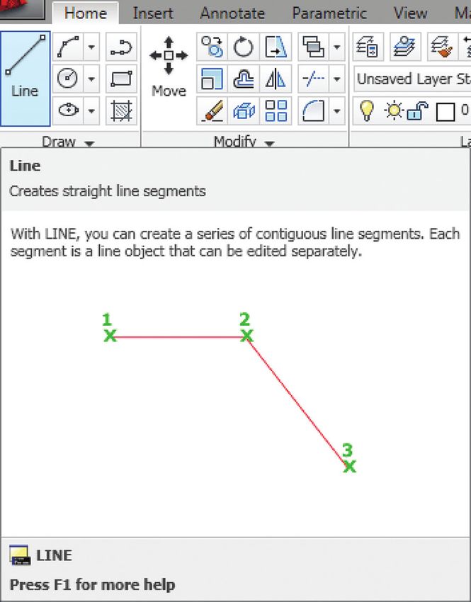
34         chapter one

Fig. 1.8                                        The Quick Access Toolbar

                                                To the right of the Application Menu is the Quick Access Toolbar, which
                                                contains many of the same commands.

 a    b         c   d       e   f   g
                                                  1)   Hover your mouse over the buttons to see their tooltips: New...
                                                       (Fig. 1.8a), Open... (b), Save (c), Save As... (d), Undo (e), Redo (f), and
                                                       Plot... (g) (or Print...).
                                                       Notice that to the right of the Undo and Redo buttons at e and f are
                                                       downward arrow buttons that each open a drop-down list of recent
                                                       actions you performed in your drawing. You can jump to any of
                                                       these actions with just a click.

                                                The InfoCenter

                                                Included on the right side of the title bar is the InfoCenter. Its two key
                                                features are the Help button at Fig. 1.9a and the Type a keyword or phrase
                                                search field at b.
                                                   The Help button (a) simply launches AutoCAD 2011 Help in your default
                                                browser.

* You can also launch the Help                    1)   Click the Help button.
home page by typing “Help” in the                      The AutoCAD 2011 Help home page will open. Notice the Search
command line and pressing Enter.                       field at the top right of the website and, in the navigation bar on the
                                                       left, the User’s Guide and Command Reference links are particularly
                                                       useful.*

Fig. 1.9                                        You can also find information on a topic directly within AutoCAD. Try the
                                                following example.

                b                       a         1)   Type InfoCenter in the search field at Fig. 1.10a and press Enter.
                                                       A drop-down list appears. Notice that within the list, major dark
                                                       grey headings collapse and expand vertically with a click, and there
Fig. 1.10                                              are navigation arrows to the right of the subsection headings (b) to
                                                       allow you to scroll through more information horizontally.
            a
                                                  2)   Click Search For Information at c under the User’s Guide section.
                                                       A browser window will open the appropriate section of AutoCAD
                                                       2011 Help.
                                            b

                        c
introducing autocad 35
Workspaces
1
A workspace is the collection of items
that are set up to create different user
interfaces (UI) for specific types of
drawings. If you look at Fig. 1.12 (page 36),
the workspace is made up of the ribbon,
drawing area, command window, and
status bar.
AutoCAD offers several different
workspaces. Set designers and drafters
are most likely to use the 2D Drafting
& Annotation workspace and the 3D
Modeling workspace.
For the technical drawings of the
set, we’ll work with 2D Drafting &
Annotation, which opens by default
when you launch the application for
the first time. We’ll also work with the
3D Modeling workspace in Chapter 6 to
create a three-dimensional drawing.
Check to see whether your workspace
is set to something other than the default.
If it is, change it back now:
1) Click the Workspace drop-down menu at the top left of the
application.
2) Select 2D Drafting & Annotation at Fig. 1.11a. Fig. 1.11
After using a workspace, you will quickly become accustomed to where
things are located and be able to work efficiently. a
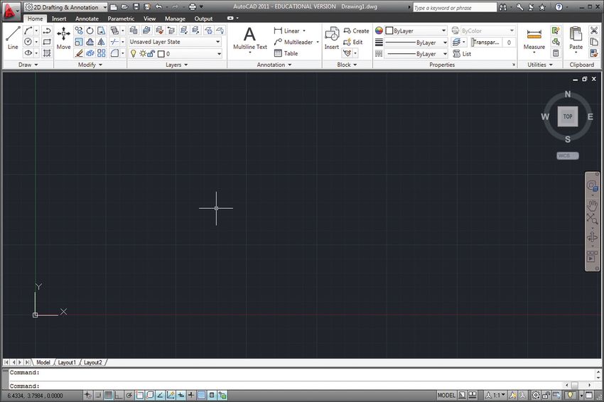
The 2D Drafting & Annotation Workspace
Now let’s examine some basic components of the two-dimensional
workspace.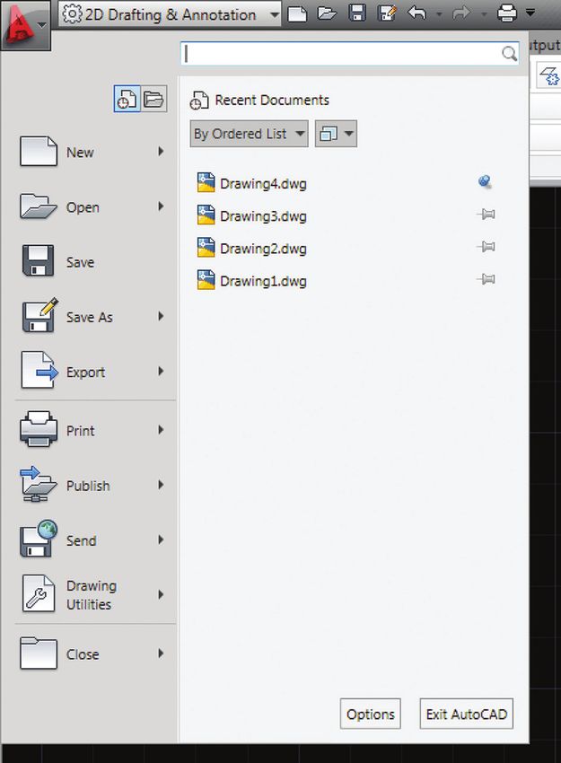
36          chapter one

Fig. 1.12

Application
menu           Quick Access Toolbar                                       InfoCenter

                                                                                                        title bar

                                                                                                        ribbon

                                                                                                        drawing
                                                                                                        area

                                                                                                        command
                                                                                                        window
                                                                                                        application
                                                                                                        status bar

Fig. 1.13                                 Fig. 1.14   The Ribbon
                   a

                                                      Below the title bar in Fig. 1.12, you will find a palette
                                                      called the ribbon which contains many of the
                                                      application’s commands and options.

                                                         1) Click the Home, Insert, etc., tabs on top.
                                                            You’ll see that each contains different sets of
                          b
                                                            command buttons inside rectangular panels.
                                                         2) In the Home tab at Fig. 1.13a, click the arrow
                                                            next to the title of the Draw panel at b. This
                                                            opens a menu called a slide-out or fly-out
                                                            menu, which contains additional commands.
                                      a                  3) Click other arrows on the panels and you’ll see
                                                            they also contain additional command buttons.
                                                         4) Whenever you need to, click the push-pin
                                                            button (Fig. 1.14a) to lock a slide-out menu
                                                            open.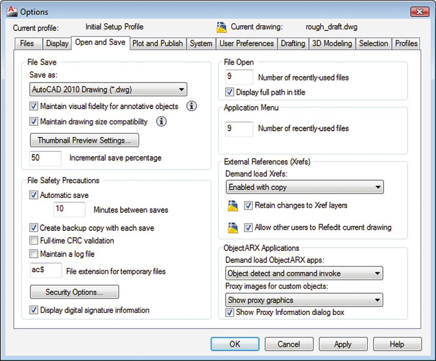
introducing autocad   37

Tabs and Panels
                                                                                                       1
As you just saw, the ribbon contains buttons that allow you to activate
AutoCAD commands or display options and information. The buttons
we’ll use frequently in the beginning can be viewed in the Home tab
panels:

       Draw activates drawing commands such as Line, Arc, Circle,
       Rectangle, Polyline, and Hatch, which you will use to draw lines
       or objects.

       Modify activates commands that allow you to modify lines and
       objects you have drawn. Some examples are Erase, Rotate, Scale,
       Stretch, Copy, Mirror, Offset, and Fillet.

       Layers activates commands to add drawing layers, or hide or
       lock them. This panel also contains commands to configure layer
       Linetypes and Colors, and to select the Current layer to draw on.

       Properties controls the properties that are associated with each
       object that you have drawn. Several drop-down lists can control
       object Color, Lineweight, Linetype, Transparency, and Plot Style.
       Most objects inherit the default properties assigned to them by
       the layer (ByLayer) in which they are drawn, but groups of objects
       called blocks can be assigned their own properties (ByBlock)
       and individual objects can also be assigned their own unique
       properties.

       Utilities contains commands used to measure a Distance, Radius,
       Angle, and Area in a two-dimensional drawing. It will come in very
       handy when we begin drafting. Besides the measuring commands,
       you’ll find the ID Point button, which is used to determine the
       exact location of a point.

Later when we add measurements and labels to drawings, we’ll also
examine panels such as Dimensions in the Annotate tab and we’ll learn
about panels that are specific to 3D drawings. If you don’t understand
much of this right now, don’t worry; you’ll catch on as we put it into
practice.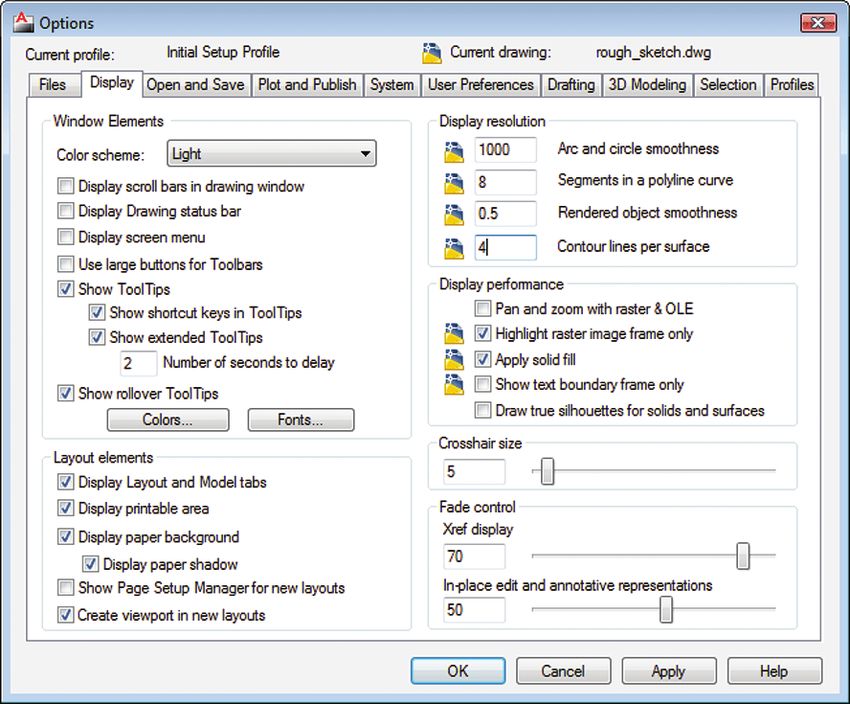
38          chapter one

                          Tooltips and the F1 Key

                          A great feature to take advantage of on the ribbon is the tooltip. Pause your
                          mouse pointer over a button on the interface, and a small pop-up tip will
                          appear. As you can see in the Line command tooltip in Fig. 1.15, you can
                          press the F1 key to open the related help topic (a) while the tooltip is active
                          or after the command is activated.

Fig. 1.15                                      The Minimize Ribbon Button

                                               Another neat feature of the ribbon is the space-saving
                                               Minimize button. It’s a small upward arrow button to
                                               the right of the Express Tools tab (Fig. 1.16); notice the
                                               small drop-down arrow next to it.

                                                  1) Click the drop-down arrow (Fig. 1.16a).
                                                     You’ll see a menu with four options for
                                                     minimizing the ribbon.
                                                  2) Select one of the first three options to set the
                                                     level of minimization you want.
                                                     The Cycle through All option at c sets the
                                                     button so you can alternate between all three
                                                     minimization levels.
                                                  3) Now, click the upward arrow button at b.
                                                     See how you can switch between the full ribbon
                                                     and the minimized option you chose.
                                                  4) Click it again to switch back.

                a                                                         Fig. 1.16

                                                                                 a
                                                                      b

                                                                      c
introducing autocad 39
Fig. 1.17
1
command line
The Command Window
At the bottom of the Application Window, you’ll find the command
window (Fig. 1.17). This is a palette that gives you feedback by displaying
commands, options, messages, and variables. It also prompts you for
keyboard and mouse input. The chronological list of every command
you’ve activated during a work session can be seen by using the scrolling
arrows at the right or by resizing the window using the vertical resize
handle on the top edge of the palette.
The input line at the bottom of the command window is called the
command line. It allows you to use the keyboard to tell AutoCAD what
to do.
Often when you activate a command by pointing and clicking your
mouse, the command window lets you know what your next step is and
what information you have to enter.
The Application Status Bar
You’ll find the application status bar (also called the status bar) at the
bottom of the workspace. The status bar contains several buttons for
turning drawing and display options on and off. These buttons are high-
lighted in blue to indicate that they are turned on. We’ll turn on these
buttons as we need them throughout the manual. For now, toggle them
all off.*
At the left end of the status bar, you’ll see three sets of numbers * You’ll need to pay a little more
separated by commas (Fig. 1.18a). This is the drawing coordinates display. attention to the Transparency
The first number is the X coordinate of your cursor and the second one button, which still looks highlighted
is the Y coordinate. The X coordinate refers to the horizontal location of when it is turned off.
a point on a grid, whereas the Y coordinate refers to the vertical location
of the same point. The third number, known as the Z coordinate, is only
active when you draft in 3D. Together, these display the coordinate values
of your current cursor position within the drawing area.
Try moving your cursor around to see how its coordinates change at ** Looking at the coordinate values,
Fig. 1.18a.** you’ll see that inches are displayed
in decimals. This is done for the sake
of precision, but it is more common
Fig. 1.18 to format inches with fractions.
We’ll change this a little later.
a40 chapter one
Fig. 1.19 Floating and Docking Workspace Elements
a
AutoCAD lets you personalize the workspace the way you like it. By
default, the tabs and panels adhere to the docking region at the top, sides
and bottom of the drawing area. But as you’ll see, you can easily drag items
around the interface. For example, you can drag the tabs to change their
order. It’s also possible to detach and reattach palettes and panels at your
convenience. This is called floating and docking.
Fig. 1.20
To float a panel:
1) Click the panel’s name to drag it into the drawing area at Fig. 1.19a.
The panel will float and its move handle will appear on its left. You
can move it around and place it where you like.
b 2) Click the Return Panels to Ribbon button at b to reset it in the
ribbon. Or drag it back into place on the ribbon.
a To float the ribbon:*
1) Place the cursor over any tab and right-click to see the ribbon’s
context menu (the right-click menu).
* The name of the palette becomes 2) Select Undock at Fig. 1.20a.
visible once it’s floating. The ribbon palette will float on the drawing area.
3) Right-click the palette’s move handle, which is the vertical grey bar
** If you accidentally close the float on its left, and you’ll see the Properties menu at Fig. 1.21a. (Note
ing ribbon palette, just enter the that you can also get this menu by clicking the third button from
word “ribbon” in the command line. the top.) This will give you options to dock the ribbon to the left or
right of the drawing area. When you need more space, the Auto-
Fig. 1.21 hide option at Fig. 121b can be handy. You can also prevent a palette
from docking if you prefer it to float by default.**
b
For now we’ll return the palette to its original spot.
a 1) Press and hold the move handle and drag it back to the top of the
drawing area to see what happens.
When the pointer approaches the edge, the palette will be replaced
by a rectangular outline indicating it is ready to be docked.
2) Let go, and the ribbon will dock itself.***
Now that you are familiar with the interface, you can rearrange the
*** You can often double-click the workspace the way you like it. The Save Current As… item of the
move handle of a floating or docked Workspace drop-down menu lets you name and save your customized
palette to instantly change its state. workspace.
Try double-clicking the move handle
of the command window to float it.
Now do it again to dock it.introducing autocad 41
Fig. 1.22
The drawing’s Minimize, Restore/ 1
Maximize, and Close buttons
ViewCube
Navigation
bar
Crosshair
cursor
World Coordinate System (WCS)
The Drawing Area
The area reserved for drawing files is the dark space in Fig. 1.22. This
is called the drawing area. AutoCAD uses dark grey as the default
background colour. **** **** Often the drawing area in this
Notice the drawing’s Model tab (Fig. 1.23a) at the bottom left of the manual has been changed to white
drawing area. It shows you that you are currently working in the drawing’s for the sake of clarity. If you’d like
model space. to change the background colour,
right-click the drawing area and
select Options… from the context
1) Click the Layout 1 tab at the bottom left of the drawing area
menu. Then select Display, click the
(Fig. 1.23b).
Colors… button and choose White
The MODEL button (not the same as the tab) on the right side of the from the Color: drop-down menu;
status bar will change to PAPER to show that paper space is turned click the Restore all contexts button
on. This white area represents a sheet of paper used when your to return to the default colours.
drawing is ready to print.
2) Click the Model tab (a) at the bottom left of the application window
to return to model space.
Fig. 1.23
The ViewCube
You can see the ViewCube in the upper right corner of the drawing area. a b
We will cover this in Chapter 6, so we’ll turn it off for now.
1) Click the View tab on the ribbon.
2) Locate the Windows panel.
3) Click User Interface. A drop-down list will appear.
4) Uncheck ViewCube.42 chapter one
Fig. 1.24 The Navigation Bar
The navigation bar contains tools that help you look at your drawing. You
can decide which tools are visible by clicking the arrow for the fly-out
options menu at the bottom of the bar. The most commonly used tools for
2D drawings are the Pan and Zoom tools (see Fig. 1.24a and b). We’ll look
at these in detail later.
The World Coordinate System (WCS) and User
Coordinate System (UCS)
Remember the drawing coordinates at the left of the status bar? They
are measured in relation to the world coordinate system (WCS). If you
think of the drawing as a digital world, the WCS is the fixed origin of the
coordinates that define a drawing’s points. When the Grid Display setting
on the status bar is on (turn it off after you experiment), you’ll also see a
red horizontal line representing the X-axis and a green vertical line for the
a
Y-axis of the coordinate system.
b When the origin is within the drawing area, the WCS icon will overlay
the origin. If the origin is not in the drawing area, the icon will dock itself
in the lower left corner of the drawing area.
Sometimes it is useful to move the origin to create a user coordinate
system (UCS), which gets its name because it is user-defined. However,
when an object with a UCS is copied from one drawing to another,
AutoCAD will always drop the UCS and reorient the object to the WCS. As
a general rule, try to stick with the WCS. There is no need to worry much
about UCS yet, as this is a fairly advanced topic.
Fig. 1.25
WCS with origin visible within drawing area Docked WCS with origin outside of drawing areaintroducing autocad 43
Working with Drawing Files * Throughout the manual, tables
such as Table 1.2 are provided 1
Drawing files are the most important documents for your project because to show you ways to activate a
they store your work. They are opened in the drawing area and saved command either with your mouse or
with your keyboard.
separately from the rest of the workspace.
Creating New Files from Templates
Table 1.2. New command
AutoCAD starts new documents from templates. A template contains a
set of preferences allowing you to create new files without having to make 8 Application menu:
changes to the settings each time. For example, templates set drawing units
and the background colour of the drawing area.
As we’ve seen in Fig. 1.12, when AutoCAD launches, a new file called >
Drawing1.dwg opens with it by default. This is typically a file made from a
template that contains preferences for two-dimensional drafting. 8 Quick Access Toolbar:
Let’s cover the New command to give you a better idea of templates.* (New/Qnew)
It’s time to create a new file. 7 Keyboard shortcut:
Ctrl + N
1) Click the Application Menu in the upper left corner of AutoCAD. 7 Command line entry:
2) Select New > Drawing from the menu options (Table 1.2). The Select new
template dialogue box appears.
3) Select acad.dwt (Fig. 1.26a), which is a template file.
4) Click the Open button (b). A blank drawing called Drawing2.dwg
will open in the drawing area.
AutoCAD is used in many different industries, so it Fig. 1.26
offers a choice of templates to start drawings with.
The two that are covered in this manual are the classic
acad template and the acad3D template. Both have
decimal formatted imperial inches as the default units.
This means, for example, that a quarter of an inch will a
be displayed as 0.25″.
b44 chapter one
Fig. 1.27 Switching and Managing Drawing Windows
Just like the Application Window, drawing files also have Minimize,
Restore, Maximize, and Close buttons just below the ribbon to the right
(Fig. 1.27). These buttons are particularly useful for switching between files
Minimize Restore Close
when you are working with more than one at a time.
1) Click the active drawing’s Minimize button. Your drawing file will
minimize within the drawing area and you’ll also be able to see the
other drawing either restored or minimized.
2) Click the Maximize button for one of your two drawings so that it
fills the drawing area again.
Probably the simplest way to switch between open windows is through the
Switch Windows button.
1) Click the View tab. You’ll see the Windows panel at the right side.
Fig. 1.28 2) Click the Switch Windows button as shown at Fig. 1.28a. A drop-
down list will appear, allowing you to select the drawing you want
a to switch to.
You can also use the buttons in the Application Menu that were described
in Fig. 1.7 (see page 33).
1) Click the Application Menu (the big red A) in the upper left corner
of AutoCAD.
2) Click the Open Documents button. You’ll see the Open Documents
list appear, which allows you to select the open document you want
to work on.
Lastly, you can use the Ctrl + Tab and Shift + Ctrl + Tab key combinations
to move forwards and backwards through the sequence of open drawings.
Saving Drawing Files
Table 1.3. Sample drawing file
Drawing1.dwg Saving your files lets you store your drawings until you are ready to
work on them again. The AutoCAD drawing file extension is .dwg (an
abbreviation of “drawing”), and it is automatically added to the end of the
file names you save (Table 1.3). This file extension lets the computer know
* Remember that getting into the which application is used to open the document. If it is not visible, your
habit of saving frequently is good Windows operating system may be set to hide extensions; if so, it is useful
practice. This helps you avoid losing to change your Windows folder settings to display file extensions. If the
your work should AutoCAD or your extension is removed from a file’s name, you may encounter difficulties
computer ever crash. when you try to open it.*introducing autocad 45
Connect your USB drive if you have one—more on this later. Next,
name and save one of the files immediately: Table 1.4. Save command 1
1) Activate the Save As… command by choosing a method in 8 Quick Access Toolbar:
Table 1.5. The Save Drawing As dialogue box will open (Fig. 1.29).
2) Click the Save in: drop-down list shown at Fig. 1.29a.
3) Select your main saving location. In this book, it’s a portable USB 8 Application Menu:
drive, though you may want to save to another location.
4) Name the document rough_sketch at b.**
5) Click the Save button (c).
7 Keyboard shortcut: Ctrl + S
7 Command line entry: save
Fig. 1.29
a
Table 1.5. Save As command
8 Quick Access Toolbar:
8 Application Menu:
7 Keyboard shortcut:
Shift + Ctrl + S
7 Command line entry:
saveas
c
b
** The way you name your files
helps you sort and find them
easily. In this book, file names use
underscores (_) instead of spaces
between words. File names for
the set drawings will begin with a
capital letter while other drawings
will stick with lowercase letters.
A rule used to name files is called
a naming convention. For other
options for naming files effectively,
see Appendix A on naming files.46 chapter one
Drawing Versions
Occasionally, you may need to open your drawing files in an older version
of AutoCAD. For this situation, you have the option to save your document
in various versions of AutoCAD in the Files of type: drop-down menu.
Whenever you are in such a situation, refer to the options in Table 1.6 to
decide which file type to choose for the version of AutoCAD you will
be using.*
Table 1.6. AutoCAD versions and file types
* Note that settings such as drawing
units that apply directly to your
AutoCAD Version Files of type
document will be saved with your
file. You won’t need to reset those v13, v14, 2000, 2001, AutoCAD LT97/LT98/R 14/2000/
each time you reopen it. However, 2002, 2003 LT2000/Drawing (*.dwg)
workspace settings are not saved
2004, 2005, 2006 AutoCAD 2004/ LT 2004 Drawing (*.dwg)
with files.
2007, 2008, 2009 AutoCAD LT 2004/2007 (*.dwg)
2010, 2011 AutoCAD 2010 (*.dwg)introducing autocad 47
Displaying the Full File Path
1
If you are new to computers and AutoCAD, you may find it difficult to find
your files. It is possible to see the complete path to an open file in the title
bar if you change the Open and Save options in the Options dialogue box:
1) Click the Application Menu button.
2) Select the Options button on the lower right side of the menu (see
Fig. 1.7 on page 33). The Options dialogue box will open (Fig. 1.30).
3) Select the Open and Save tab as shown at a.
4) Locate the File Open box at the top right side.
5) Check off the Display full path in title option (Fig. 1.31a).
Another quick way to open the Options dialogue box is to right-click the
drawing area and select Options from the right-click (context) menu.
Now, whenever you have a file open in AutoCAD, you’ll be able to see
the breadcrumb trail within the title bar as shown in Fig. 1.32.
Fig. 1.30 Fig. 1.31
a
a
Fig. 1.3248 chapter one
Protecting Your Work
Drat! Computers and applications can crash. Files can become corrupted
and impossible to use. Hard drives wear out over time. USB drives can be
damaged or lost and networks can fail. In order to protect the hours of
work you’ve put into a drawing, you need to save often. However, you also
have several other alternatives to protect your work.
Backup Files
Generally, when you save an AutoCAD file, AutoCAD saves a backup copy
in the same location (Table 1.7). This is helpful if your current file gets
Table 1.7. Backup file example
corrupted; simply replace the .bak extention with .dwg to regain your file.*
Drawing1.bak
File Histories and Email
Every time you open an existing file, work on it, and then save it again,
you overwrite your previous work. Each time you save, it represents a step
* Consult the Backup Files Location in the development of your project. If you only save a single file, you are
and Automatic Saving sections of essentially keeping all your eggs in one basket, and you risk having to start
Appendix B for more information on all over again if the file ever gets corrupted.
protecting your files. A simple solution is to save versions of your work to create a history.
Simply add a number to the end of the file name each time you make
significant progress in your project (Table 1.8). Then store older versions of
your files in a separate folder.
Table 1.8. Sample file version
history An even easier and thriftier way to create a file history is to email
yourself copies of your files after your work sessions. This will give you a
Dussol_Ground_Plan_1.dwg chronological series of drawings in both the Sent and Inbox folders of your
email account. What’s great about an email account is that it also serves as
Dussol_Ground_Plan_1.1.dwg
storage device if you’re on a tight budget.
Dussol_Ground_Plan_1.2.dwg Don’t take the risk of losing all your work! With a file history, you’ll at
least be able to return to a previous step in your project without having to
start from scratch.
Hardware Storage Devices
** Remember that if you remove
your USB drive without ejecting Another way to safeguard your work is by saving your files to different
first, the file system can be storage devices. This is important in case any one device breaks down. To
corrupted and you could lose access protect your work, take advantage of storage media such as USB memory
to your files. Always right-click it drives, email accounts, hard drives, and network servers when available.
and choose Eject from the menu
The rule is to keep copies of your files on more than one hardware
before pulling it out.
device at a time. Let’s assume that you own a USB drive, have a web email
For more strategies for protecting
your work, see Appendix B on
account, and work on school computers that are linked to network servers.
Extended File Protection. These are four locations that you can use to store backup files.**introducing autocad 49
Table 1.9. Proposed file storage locations for a student 1
Main Storage Thrifty Storage Temporary Storage Backup Storage
External USB
storage drive Email account server Computer hard drive Network server
Beginning with Basic Drawing Tools
And now for the words you’ve been desperately waiting for: Let’s draw!
Here are a few tools you will need to start drawing lines.
The Escape Key
While you draw, it’s helpful to know that when you activate a command
in AutoCAD, you can normally use the Escape key to deactivate it. The
same holds true for many other operations you might want to escape
from. For example, if you accidentally clicked the Open… Ctrl + O option
in the Application Menu, simply press Escape (see Fig. 1.33a) to cancel the
operation and return to your work. Keep the Escape key in mind whenever
you’re trapped in a sticky situation.
Fig. 1.33
a esc F1 F2 F3 F4 F5 F6 F7 F8 F9 F10 F11 F12 psc slk brk
/ 1 2 3 4 5 6 7 8 9 0 - = bksp ins hm pup nlk /
tab q w e r t y u i o p ^ ç à del end pdn 7 8
lock a s d f g h j k l ; è ent 4 5
shift z x c v b n m , . é shift 1 2
ctrl alt alt ctrl 050 chapter one
The Line Command
Table 1.10. Line command
If you haven’t stopped working since the previous sections, you should
8 Home tab:
have two drawings open: rough_sketch.dwg and Drawing2.dwg. If you don’t
Draw panel >
already have rough_sketch opened, open it now (see Table 1.12 for the Open
command).
There is a choice of methods to activate the Line command. Now is the
7 Command line entry: time to experiment with them.
l or line *
1) Click the Line command in the Home tab (Table 1.10). Notice that
whichever method you use to activate the Line command, the
command window will prompt you with this message:
* Note that only a few commands
Command: _ line Specify first point:
allow you to type the first letter as
a shortcut. The application is asking you to specify where you would like to
start your line.
2) Place the cursor (also called the crosshair cursor) anywhere in the
drawing area and click the mouse. The command window will offer
you the choice to…
Specify next point or [Undo]:
The second choice in the square brackets means that you can
enter U to undo the last point without deactivating the command.
3) Move your cursor around the screen and you will notice that a line
follows it from the first point you specified. This is known as the
rubber band line.
4) Now click anywhere in the drawing area to complete the first
segment of your line. Notice that the command window keeps
prompting you for the next point. You can keep adding as many
segments to the line as you wish.
5) End the line by doing one of the following:
► Press Enter on the keyboard.
► Right-click in the drawing area and select Enter from the context
menu.
► Press the Escape key.introducing autocad 51
The Undo Command
Table 1.11. Undo command 1
Often you’ll find that you make mistakes and need to return to an earlier
stage in your drawing to make a correction. Like most applications, 8 Quick Access Toolbar:
AutoCAD lets you undo the steps you’ve completed.
Both the Quick Access Toolbar and the command line allow you to
undo several steps at once (Note: You must have completed at least one 8 Context (right-click)
menu: Undo
command in order to undo it). You’ll notice that the Undo button is
accompanied by a drop-down list (Fig. 1.34), which displays a history of 7 Keyboard shortcut:
steps completed. Select one of the items in the list to return to a previous Ctrl + Z
stage of your work. 7 Command line entry:
Similarly, when you enter the Undo command in the command line, the undo, u
command window will prompt you to enter the number of steps backwards
that you would like to take.
Command: Undo Fig. 1.34
Current settings: Auto = On, Control = All,
Combine = Yes, Layer = Yes
Enter the number of operations to undo or [Auto/
Control/BEgin/End/Mark/Back] :
Some current settings are displayed in the command window, but notice
what’s written in the command line: . The number in angle brackets at
the end of this prompt indicates the default number of “undos,” which is
set to 1. You can either just press the Enter key to automatically undo one
command or enter another number and press Enter. (Note that any new
number you enter will become the default, so try to stick with 1 for now to
avoid confusion.)
Guess what? You can undo an Undo. This is called Redo and you’ll
notice that the Redo button is to the right of the Undo button.
The Space Bar
Whenever you have used a command and need to use it again, simply press
the Space Bar to reactivate it. Try drawing a line. Now press the Space Bar
to reactivate the Line command. How handy is that?52 chapter one
Selecting and Shift-Selecting
To select several lines or objects there are three alternatives:
► Simply click them one by one.
► Drag from left to right to draw a window selection box (Fig. 1.35a) around
them with the cursor; the objects must be inside the box to be selected.
The resulting light-blue box has a solid outline.
► Drag from right to left to draw a crossing selection box (Fig. 1.36a) that
simply touches the objects you want. The resulting light-green box has a
dashed outline.
Whenever you select an object in the drawing area, it becomes ghosted
(Fig. 1.37), which means that the line pattern changes to dashed and blue
grips appear to help you manipulate it as shown at Fig. 1.37a.
If you accidentally select too many lines, simply press the Shift key and
click the objects you want to deselect.
Fig. 1.35
a
Fig. 1.36 Fig. 1.37
a aintroducing autocad 53
Drawing a Rough Sketch
1
SHAKESPEARE. I would like you to create a rough
sketch of the ground plan for A Matter
of Murder and Peerage in the Scottish
Manor to give me a taste of all this
modern technology. I hear that using
AutoCAD for drafting looks a little
different from using a pencil and I
would like to compare.
Let’s give this sketch a try.
Opening a File
Before you begin, make sure that your external storage
drive is connected to the computer and that the
rough_sketch.dwg file you previously saved is open.
1) Activate the Open command (Table 1.12). The Select File dialogue
box will open (Fig. 1.38).
2) Now select the file as shown at Fig. 1.38a and click the Open button
at Fig. 1.38b (or simply double-click on the file name to open your
document).
Fig. 1.38
Table 1.12. Open command
a
8 Quick Access Toolbar:
8 Application Menu:
7 Keyboard shortcut:
Ctrl + O
7 Command line entry:
open
b54 chapter one
Drawing Freehand
We are going to draw a ground plan freehand style. Sometimes this is
called the interactive method of drawing; it allows you to test out your
ideas quickly. It’s not quite drafting because the drawing is not scaled or
measured, but it will let you to get a feel for drawing with AutoCAD. This
method can be useful for testing different possibilities for a stage layout.
* You’ll notice “do-it-yourself ” Do It Yourself *
headings such as the one on the Referring back to what we’ve already covered, recreate the drawing pictured
right throughout the manual. They in Fig. 1.39 as closely as you can.
indicate that you can apply what
you’ve learned earlier to complete
the task on your own.
In Fig. 1.40, notice there is a Preview box (a). This is where a thumbnail
image of your drawing shows up before you open it. In order for it to show
your entire drawing, your drawing needs to be centred in the drawing area
before you save it.
Fig. 1.39introducing autocad 55
Fig. 1.40
1
a
1) Locate the navigation bar. ** In general, this book asks you
2) Click the Zoom Extents button. (Hover the pointer over the buttons to save to a USB drive. However,
to see the tooltips if necessary.) AutoCAD is increasingly available
3) Save the sketch.** for students to install on their own
computers. If you have your own
copy of AutoCAD, feel free to save
your drawings to your personal
Chapter Summary computer.
Skills Learned
You now know the names of AutoCAD’s interface elements. You can open,
switch between, and save drawing files as well as apply strategies to protect
your work. Finally, you know how to use some basic drawing commands
to draw lines, undo and escape from commands, and reactivate commands
quickly through the keyboard.
Project Check
You created and saved this file: rough_sketch.dwgYou can also read