Collecting structured logs of instances as process nets in Petriflow language
←
→
Page content transcription
If your browser does not render page correctly, please read the page content below
Collecting structured logs of instances as process
            nets in Petriflow language

    Gabriel Juhás1,2 , Tomáš Kováčik1,2 , Jakub Kovář1,2 , and Martin Kranec1,2
            1
                Faculty of Electrical Engineering and Information Technology,
                       Slovak University of Technology in Bratislava,
                          Ilkovičova 3, 812 19 Bratislava, Slovakia,
                                       2
                                          NETGRIF, s.r.o.,
                      Slávičie údolie 106, 811 02 Bratislava, Slovakia
                                     netgrif@netgrif.com
                              Home Page: https://netgrif.com

         Abstract. In this paper, we present a prototype of a module of the Pet-
         riflow application engine that stores process nets for each single case of a
         Petriflow model, whose underlying process model is a place/transitions
         net. It enables to filter cases according to search queries and to export
         the process runs for the filtered cases within a compressed form, contain-
         ing each process net in a separate file. The process nets can be used for
         further analysis or as an input of process mining methods. Each process
         net can be opened in the application builder and simulated. As parame-
         ters in the search, we chose fact transitions that are used to identify the
         set of markings of the instance of the business model.

         Keywords: Petriflow · Process-driven programming · Petri nets · Pro-
         cess nets

1     Introduction

Using place/transition Petri nets [1] one can model simple processes in a short
time with only a basic knowledge of the modeling language. However, in order
to model all the aspects necessary to implement a real application that should
be deployed, the place/transition Petri nets need to be extended in an appro-
priate way, such as for example Coloured Petri Nets [2]. Although there are
several tools for modeling and analysis of different variants of Petri nets, includ-
ing Colour Petri Nets, such as CPN Tools [3], most of them are developed with
the purpose to serve the academic community, but up to our knowledge, they
do not offer a process engine used in industrial applications to run instances
of processes modeled by Petri nets. For that purpose, recently a language for
    Copyright © 2021 for this paper by its authors. Use permitted under Creative
    Commons License Attribution 4.0 International (CC BY 4.0).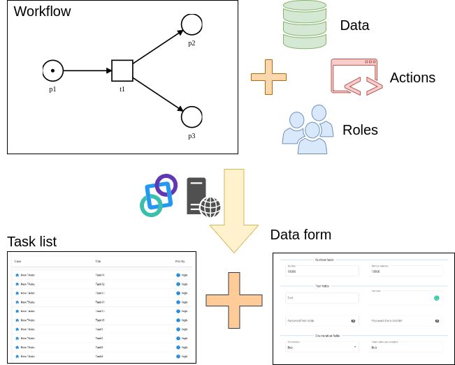
106     G. Juhás et al.

process-driven application development based on the extension of place/transi-
tion Petri nets, called Petriflow [4], was defined and the appropriate application
builder and application engine were developed. It uses the basic structure of
place/transition Petri Nets, but it already has its own extensions that are de-
signed for better modeling development. Petri nets were chosen as the basis
for this language over other process modeling notations such as the Business
Process Modeling Notation (BPMN) or the Unified Modeling Language (UML)
for many reasons discussed in the works of other authors such as [12] or [13].
Nowadays, the Petriflow processes are deployed in dozens of application engine
installations, running more than 100 million instances (cases) of the Petriflow
processes. Although the commercial version of the application engine collects
logs of the running cases in a sequential log, it is not straightforward to use this
log for analysis or for process mining, as it contains only partially structured
text. However, because the process layer of the Petriflow models is formed by
place/transition nets, extended possibly with inhibitor arcs [5], read arcs [6],
reset arcs [6] and self-modifying arcs [7], one could store the information about
history of a single cases in the form of process nets [8] or runs. For formal def-
initions of place/transition Petri nets and their process nets we refer to [8]. In
this paper we will use the term runs to denote process nets, although in liter-
ature runs often describe labeled partial orders obtained from process nets by
forgetting conditions [8]. Furthermore, we present a prototype of a module of
the Petriflow application engine that stores the process nets for each single case
of a Petriflow model, whose underlying process model is a place/transitions net.
It enables the filtering of cases according to search queries and to export the
process runs for the filtered cases within a compressed format, containing the
process net of each case in a separate file. The process nets can be used for fur-
ther analysis or as an input of process mining methods. Each process net can be
opened in the application builder and simulated. As parameters in the search,
we chose fact transitions that are used to identify the set of markings of the
instance of the business model [9].

2     Petriflow and PDP

The Netgrif Application Engine, a part of the Netgrif platform, is built to inter-
pret programs of the Petriflow language. Petriflow is a high level programming
language for process-driven application development. Petriflow follows the pro-
gramming paradigm called process-driven programming (PDP). A comparison
of Petriflow’s concept with other well-known programming paradigms is essential
to understand the meaning of the PDP paradigm. In this section, we discuss how
process-driven programming extends and combines advantages of object-oriented
programming (OOP), the business process modeling (BPM), event-driven pro-
gramming (EDP) the and relational databases (RDB).
    While binding methods with data in classes was one of the main features
of OOP that helped to create more modular programs, PDP adds processes
to classes to describe a life-cycle of objects of a class. In this way, by adding
Collecting structured logs of instances as process nets in Petriflow language 107
processes that define when methods of a class can be called and who can call
these methods, applications can be programmed easier, faster, and therefore
cheaper.
The main building blocks of object-oriented programs are classes and their
objects. In comparison, the main building blocks of process-driven programs
in Petriflow language are processes and their instances called cases. A class is
a blueprint of an object and a Petriflow process is a blueprint of a Petriflow
process instance. Simply, a Petriflow process is a class enriched by a workflow
process that defines a life-cycle of the objects of that class.
More accurately, a Petriflow process consists of data, tasks and actions, roles,
and a workflow process. The Petriflow processes can be deployed to any com-
patible workflow engine, such as the Netgrif Application Engine to create rich,
process-driven applications as seen in the illustrative overview in figure n. 1.
Fig. 1. Overview of a PDP platform
In the same way as classes in OOP, data variables in the Petriflow processes
represent all attributes of a Petriflow process instance. The change of the value
of a data variable can be triggered by a so-called set-event. Reading a value of a
data variable can be triggered by a so-called get-event.
Tasks are the active parts of the Petriflow processes. Data variables can be
associated with workflow tasks to define data fields and create task forms. A
data field, which is an association of a data variable to a task, is given as a rich
relation, that states108 G. Juhás et al.
– whether a get-event and/or a set-event can trigger the data variable, i.e.
whether its value is readable and/or editable,
– whether the value of the data variable is required,
– what are the valid values of the data variable within the data field.
Tasks have a simple life cycle: a task can be enabled, disabled or executed.
Change of the state of a task can be triggered as follows:
– if a task is enabled, its change to the state executed can be triggered by a
so-called assign-event
– if a task is enabled, its readable data fields are accessible for reading by
get-events
– if a task is executed, its readable data fields are accessible for reading by
get-events
– if a task is executed, its editable data fields can be changed to valid values
by set-events
– if a task is executed and all its required data fields have valid values, its
change to the state enabled or disabled can be triggered by a so-called finish-
event.
Fig. 2. Lifecycle of a task represented by a Petri net [14].
Using the principles of event-driven programming, each data variable and
each task has an associated event listener: whenever an event triggers a change
of the value of a data variable, or whenever an event triggers a change of the
state of a task, then a reaction can be defined by pieces of code called actions
in the event listener. Whenever an event occurs, the actions in its event listener
are executed. In actions, as a part of the code, events for tasks and events for
data variables can be emitted. In this way, events and their reactions can create
chains.
Roles or lists of users can be associated with events of tasks, defining for
each task which users are authorized to emit events on that task. Similar to
data fields, the association of users with events is a rich relation. For example,
a user authorized to emit an assign-event of a task can emit the assign-event.Collecting structured logs of instances as process nets in Petriflow language 109
By emitting the assign-event, this user has to choose one of the users that are
authorized to possibly emit finish-event of this task and only this user is then
authorized to emit set-events of editable data fields of this task and to emit the
finish-event of this task. In other words, by emitting the assign-event, the autho-
rized user is assigning that task to a user (possibly himself), that is authorized
to perform the task, i.e. to fill editable data fields and finish the task.
As a workflow process, Petriflow language uses place/transition Petri nets
enriched by reset arcs, inhibitor arcs, and read arcs to define the life cycle of
the Petriflow process. Places of the Petri net represent the control variables.
Transitions of the Petri net represent tasks of the workflow process. A task
is enabled, whenever the corresponding transition in the underlying Petri net
is enabled. An assign-event occurring on this task consumes tokens from the
input places of the corresponding transition and moves the state of the task
to being executed. A finish-event on the task be executed produces tokens to
the output places of the corresponding transition. In this way, the workflow
process defines when a task is enabled, executed, or disabled. The life-cycle of
the Petriflow process is given as a flow of assign/get/set/finish events on tasks
and data variables respecting the restrictions on events given by the underlying
Petri net.
When drawing a parallel between relational databases and process-driven
programming, the Petriflow processes correspond to database tables, while in-
stances (cases) of the Petriflow processes correspond to single records (rows) of
these tables. In a similar way to foreign keys in RDBs and in a similar way to at-
tributes of objects containing references to other objects in OOP, data variables
of Petriflow processes can store references to instances of Petriflow processes,
references to a single task, and references to a list of tasks of Petriflow process
instances. These stored references to Petriflow tasks allow for a simple way of
sharing the forms associated with them as subforms within other tasks and to
implement a single source of truth architecture.
3 Netgrif Application Engine
The Netgrif Application Engine (NAE) is a tool for deploying and running
process-driven applications written in the Petriflow language. NAE is composed
of several building blocks. The core of the NAE is the Process Engine Server,
which enables to:
– Upload, run and delete Petriflow processes
– Create, run and delete instances of processes
– Assign, finish and cancel tasks of process instances
– Read and save data variables
– Execute actions
Sometimes you do not want to change the process to react with an action to an
event. It usually happens if you want to react with the same action to more than
one event in different processes. The Rule Engine allows you to specify if-then110 G. Juhás et al.
decision rules written in the MVFLEX expression language (MVEL). Whenever
an event is triggered, then the Process Engine Server checks the Rule Engine,
whether there is a rule such that its if condition is valid for the event. In such
a case, the Rule Engine executes the then statement of the rule. In the then
statements of rules, you can trigger events of the Process Engine Server. The
Rule Engine is based on Drools.
The Process Engine Client provides a user interface in the form of Angular
components for displaying task lists, task forms, and data fields. The Process
Engine Client communicates via a REST API with the Process Engine Server.
Using the web address of the Process Engine Client followed by the ID of a
process instance, the list of enabled tasks of the created process instance, the
so-called case view, is displayed by the Process Engine Client. If the name of
a process is used instead of the ID of an instance, the create event is triggered
and the Process Engine Server creates a new process instance. You can see the
architecture of the Process Engine stack in figure n. 3.
Fig. 3. Architecture of Process Engine [11].
In the task list, you can expand a task to display the task form, triggering
get events for all the referenced data fields. Once a task form with all its data
fields is displayed, the assign event of the task can be triggered. Once a task is
assigned, the cancel event can be triggered, the set event can be triggered for
editable data fields and when each of the required data fields has a valid value,
the finish event of the task can be triggered.
The Process Engine Server, the Rule Engine, and the Process Engine Client
together with a set of predefined processes for managing roles, users, authentica-
tion, and authorization of the users, deploying Petriflow processes is provided as
a Default Process Driven Application. The Default Process Driven ApplicationCollecting structured logs of instances as process nets in Petriflow language 111
allows you to administrate the processes by deploying and deleting the processes,
to invite users, and to add/remove roles to/from users. It offers the functionality
of registering users. For registered users, it offers the functionality of a task list,
where you can assign and perform the tasks associated with one of the roles of
the registered user filling the task forms by editing the data fields. For anony-
mous users, it offers the ability to fill public task forms of public processes and
to access the instances of the public processes via the ID of the process instance.
Even if the rich functionality of the NAE and the Petriflow language is not
enough, you can go beyond its functionality by overriding the predefined com-
ponents. In this way, you can, for example, add new menu items associated with
Petriflow filters, add connectors to your own systems, or customize the Angular
components to be displayed according to your own design manual.
3.1 Search in the NAE
As mentioned before, the Process Engine Client comes with a predefined library
of Angular components. One of these components is the search component. The
purpose of this component is to allow users to filter the cases or tasks that are
displayed in the client. The search component can operate in two modes. The
first, also called the full-text mode, is a familiar input field that allows users
to search for substring matches in case or process attributes predefined by the
developers.
The second mode is a more recent addition to the Process Engine Client
component library and the goal for its creation was to allow the users of the
application to have finer control over the created filter. This second search mode
is more commonly called the advanced search mode. The filters it can create
have a predefined structure, which is a conjunction of disjunctive clauses. The
users can add as many clauses as they desire and each clause can also have an
unlimited number of literals. The literals that can be used are the basic building
blocks of the search component and are called search categories. The set of search
categories, available when searching cases, is different from the categories, avail-
able when searching tasks. Each category represents a query on some attribute
of the filtered objects. The way a certain attribute is queried is determined by
a search operator. Each search category defines a set of operators that can be
used with it. For most categories, this set is relatively straightforward. The only
exception is the case data category, which queries a subset of the case’s data
set. The developers must mark data variables as available for searching, which
determines the extent of this subset. It is the most complex category available
as the queried data variable must be selected first, which in turn, based on the
variable type, determines the set of available operators.
This design allows for a relatively high degree of freedom when creating a
search query, without the need to write the underlying filters by hand. When even
more complex filters are required, the developers can write them freely by hand
as the underlying query language does not impose any structural limitations on
the queries.112 G. Juhás et al.
Fig. 4. Search component in advanced search mode.
4 Netgrif Application Builder
The Netgrif Application Builder (NAB) is a tool for building process-driven
applications using Petriflow language. NAB is composed of several modules that
help you in different stages of application development.
In Process Modeler you can model business processes by defining tasks and
their routing and simulate modeled processes by executing sequences of tasks. As
a modeling formalism for processes Petriflow language uses Petri nets that consist
of state variables, tasks, and their interconnections. It supports the import of
processes in BPMN 2.0 and its automatic translation into Petri nets. In figure n.
5 the Process modeler with an example net is shown, which we use in our case
study later.
Fig. 5. Screenshot of Process modeler with example net, which is explained later in
case study.
In the Role Editor, you can define roles and specify which roles can perform
tasks in the process.
In the Data Editor, you can define data variables used in the processes.
Petriflow supports all types of data variables you will need for your application,
including text, numbers, date, date-time, enumerations and choices, files, images,
and many others. Validation and initial values of the data variables can be easily
specified in Petriflow. Petriflow supports reference to a list of tasks as a data
type.
In Form Builder, you can build the forms for single tasks by drag and drop
either existing data variables or adding new data variables. For data variables onCollecting structured logs of instances as process nets in Petriflow language 113
forms, called data fields, you can specify different attributes, such as placement in
the form grid layout, choose the appropriate view such as different types of check-
boxes, and determine, whether the data fields are editable, visible, required, or
hidden. Using reference to a list of tasks as a data field, you can embed subforms
to forms.
In Action Editor you can program reactions on events of process instances, its
tasks, and data fields. Actions use Groovy as a programming language. Types
of events that you can catch include construction of the process instance, as-
signment of a task to a user, cancellation of a task, finish a task, and change
of a data field value. In actions that react on events, you can trigger events in
different process instances and in this way for example create a new instance
when you finish a task, assign a new task a user when you finish the current
task, to recalculate a value of a data field whenever you change another data
field, or hide/show data fields when you change another data field. Also, in ac-
tions, you can use predefined search functions to find specific process instances
or tasks based on values of process attributes, process instance attributes, task
attributes, and data variables. In actions, you can also call external functions
as well as send and receive data from external systems via REST or SOAP web
services.
Figure n. 6 show us a source code of implementation roles in Petriflow lan-
guage. Roles consist of two parts declaration and definition on assigned transi-
tion. The role declaration defines the name and unique identifier of the role in
the process. Definition on the assigned transition identifies what action a given
role can perform on a given task.
Figure n. 7 show us a declaration of data and also how we can bind data
references with the transition. Using data references we can define which data
variable we want to show at a given transition with given behavior. Possible
behaviors are described in this paper [4].
On data variables, data references, and the transition we can defined actions
or events that can change behavior or change the value of data variables. Using
these actions, we can create dynamic forms and processes that respond to the
user interaction. Simple source code of this events/actions is show on the fig. 8.
Using NAB you can generate and download the source code in Petriflow
language that includes all the necessary information about processes, their tasks,
roles, data variables, forms, and actions.
5 Case Study
In this case study, we chose to examine the Petri Net model shown in figure 5.
It represents a simplified workflow of applying for a mortgage. The model starts
with an application form (transition Apply for mortgage) which is executed by
a user with the client role.
After the mortgage application form is sent, the model splits into three par-
allel branches. The purpose of the upper and lower branches is to make some of
the data variables accessible by the users of the application (transitions Case info114 G. Juhás et al.
Fig. 6. Roles in source code in Petriflow language.
< document ... >
...
< role >
< id > client
< title > Client
...
< transition >
< id >1
240
190
< label > Apply for mortgage
< roleRef >
< id > client
< logic >
< perform > true
...
...
and Status). The model continues with the middle branch (transitions Approve
and Reject), where the loan officer either approves or rejects the mortgage appli-
cation based on some internal criteria. This splits the process into two alternate
branches.
The lower branch represents the possible deletion of the rejected application
by the client. Note that this does not delete the model instance, as the bank still
needs to keep the information, about the rejected mortgage application, and can
still access the information, made available through the Case info transition in
the top-most branch. If the application was approved a Property appraiser must
write an Appraisal report (transition Appraisal report). After the submission
of the Appraisal report, the bank system approves or rejects the application
(transitions Approve and Reject) based on some predefined business rules. In
the simplified workflow, the application is automatically approved if the amount
of money, asked in the mortgage application form, is smaller than the appraised
value of the property. Should the application be rejected, it continues down the
already described path, which leads to the deletion of the application by the
client.
If the system approves the application, we consider the mortgage to be ap-
proved and the model continues with the signing of the contract by the client
(transition Sign loan contract). After the contract was signed, the model is once
again split into two parallel branches. In the upper branch, the Loan officerCollecting structured logs of instances as process nets in Petriflow language 115
Fig. 7. Data in source code in Petriflow language.
< document ... >
...
< data type = " text " >
< id > client_name
< title > Client ’s name
< desc > Please enter your name
...
< transition >
1
240
190
< label > Apply for mortgage
< dataRef >
client_name
< logic >
< behavior > editable
< behavior > required
...
...
Fig. 8. Events/Actions in source code in Petriflow language.
< document ... >
...
< data type = " text " >
< id > client_name
< title > Client ’s name
< desc > Please enter your name
< action trigger =" set " >
client_name: f . client_name ;
change client_name value { " Joe " }
...116 G. Juhás et al.
must confirm the lien inscription (transition Confirm lien inscription). In the
lower branch, the client signs an insurance contract for the mortgage with an in-
surance company (transition Sign insurance contract). When both of these tasks
were completed, the Account clerk can send the money to the client (transition
Send money).
We want to demonstrate with the help of this Petri net model, how our tool
creates process nets for the instances of the model running in the application
engine. Log files rarely record information about states. Here, we record the
full information about conditions in the process net. We want to use the search
capabilities described in section 3.1 to filter only instances in specific states. For
this purpose, we want to use fact transitions, as the search tool allows us to find
instances that have a marking that allows a specified transition to be executed.
For more information about fact transitions and their use for verification see.
[9]. Fact transitions visualize facts in our model. Facts specify sets of desired and
undesired markings of the Petri net. Since the search tool allows us to construct
conjunction and disjunction queries, we could mark individual states with fact
transitions and then used the search tool to filter only those instances where a
specified combination of these transitions is executable. We added one desired
fact transition at the end of the model, to find cases that successfully completed
the entire mortgage application process, and one undesired fact transition after
the Delete transition, to find cases that were rejected and deleted. Furthermore,
we added one desired fact transition with a corresponding place that is enabled
in any instance, where the mortgage was approved, as well as another undesired
fact transition that is enabled in all instances, where the mortgage was rejected.
The net containing all the fact transitions can be seen in figure 9. The fact
transitions cannot be executed by any user, so once the instance reaches either
of the states, we will always be able to find the instance.
Fig. 9. Business process net with added fact transitions.Collecting structured logs of instances as process nets in Petriflow language 117
In order to demonstrate how the tool can generate processes for running
instances, we have created an instance of the mortgage application model with
fact transitions. We executed the transitions that lead to the undesired state.
The transitions that were executed in the instance can be seen in figures 10.
p10
IN Apply for mortgage p1 Approve p3 Appraisal report p12
Reject
p2
p9 Delete p14
Fig. 10. Run of the case study net resulting in an undesired state.
Once the instance reaches its final state, we can use the fact transitions to
find it in the application engine. We can use the search query to download the
process net of the run. The algorithm that we use to generate the process runs is
described in section 6. Once we download the process net from our application
we can open it in NAB. While the algorithm does place the elements of the
process in such a way that they do not overlap each other, it does not attempt
to replicate the layout of the executed net. Therefore we changed the layout of
the output by hand to resemble the original net more closely. No other changes
were made to the generated process net. We can see the process net of the
instance in figure 11. As we can see our tool exports only the IDs of places and
transitions from the original net. This is desired, as the original net contained
two transitions named Approve and two transitions named Reject.
The process net distinguishes between them by labeling all transitions and
places with their IDs.
As we can see this tool allows us to generate process nets for running instances
of any model running in the application engine. We can then use the search
interface to select a subset of all the available cases and download the generated
process nets. We can use other tools to analyze the generated process nets, or we
can examine them by hand to check if the deployed model behaves as expected.118 G. Juhás et al.
p10
p11 Apply p1 Approve 1 p3 Report p12 Reject 2 p2
p16
p9 Delete p14
Fig. 11. Generated Process net of instance in undesired state.
6 Implementation overview
If we want to generate runs for the instances that are present in the system, we
need to represent them. Since our tool already has a working representation of
Petri nets, we can reuse it. Because of this, we have decided to represent the
runs as Petri nets. We have created a new collection in MongoDB, a database in
which we store every run as a document, we then created a mapping of running
model instances to their corresponding runs.
When a new case is created a new Petri net representing its run is generated
alongside it. This net initially contains only a set of places, where each place
represents one token in the initial marking of the original net.
When the system or a user finishes any of the tasks, the run of the corre-
sponding case must be updated. A new transition, that represents the executed
task must be added to the run of the affected case. This new transition must
consume and produce tokens according to the firing rule in the original net [8].
Each token, that ever existed in the original net, has a corresponding place in
the net that represents the run. [8] Tokens that have already been consumed are
connected by an arc with a transition that was fired at some point in the past
[8].
In order to find the places that represent the tokens that have not yet been
consumed we iterate over the arcs in the net, that represent the run. If the
arc we are currently iterating over connects a place and a transition, we know
that the token represented by the place has already been consumed. We collect
the identifiers of such places. Once we have all the identifiers of the places that
represent the consumed tokens, we can iterate over all the places and filter the
consumed places out, which leaves us only with the places that represent tokens
that have not yet been consumed.
If a transition in the original net produces multiple tokens into a single place,
each token will be represented by a single place in the run [8]. When a transition
is fired and consumes some of these tokens, it doesn’t care which exact tokens
are consumed, only their quantity is important [8]. Because of this, we need to
group the tokens by the place they originated from. Once we have the tokens
grouped, we can update the run with the new transition.Collecting structured logs of instances as process nets in Petriflow language 119
Updating the run is simple, we add a new transition, connect it to the existing
unconsumed places based on the tokens it consumes in the original net and
we add new places based on the tokens it produces. Since we have the places
grouped we have access to the required objects in the required quantities. Since
the original net enforces the firing rule [8], we know, there must be enough places
in the run to connect the new transition to.
The order in which we choose which of the yet unconsumed token are con-
sumed is important because it creates dependencies between transitions fired in
the past and the new transition in the run [8]. Since we only create one run
per case, it could be beneficial to choose the places to consume at random, in
order to cover all the possible dependencies with multiple cases. In reality, the
choice is determined by the order of iteration and since all the collections used
in the implementation impose some ordering all the runs generated by the same
firing sequence will also be the same. However, modifying the implementation
to choose the places at random would not be difficult.
Fig. 12. Petri net.
An example of a Petri net that can generate different causal dependencies
depending on the choice of places can be seen in figure n. 12. The two possible
runs that can be generated from this net when all of its transitions are fired can
be seen in figure n. 13. The current implementation will always result in the first
process net to be generated regardless of the ordering of the executed transitions.
The firing order of the transitions does not matter for this specific net, in some
nets a different ordering will create a different process nets, but in general, the
same ordering will always yield the same net in the current implementation.
Since we reused the existing Petri net representation to represent the runs,
for export we would use the same structure as for import into NAE or NAB.
We declared the structure using JAXB Annotations and using JAXB Marshaller
we created and exported it for a given individual run. Since we want to export
multiple instances at once, we need to add filtering of instances. The search tool
that is a part of NAE and, which we used to filter the instances is described
in section 3.1. One of the available search categories filters cases based on the120 G. Juhás et al.
Fig. 13. Petri net.
executable tasks in them. With the help of this search category, we can filter the
instances based on the fact transitions, as described in section 5. The created
search query must be sent to the exporter service, for this reason, we declare a
new REST controller. The controller uses the query to find the running instances
and by extension their runs. Afterward we call the service that exports each run
instance, the exported files are then added to a ZIP archive, which is uploaded
as a blob object that the browser automatically downloads.
7 Future work
When using the formal definition of the Petriflow Language to design business
processes and the subsequent generation of individual runs for a given process, it
is appropriate to think about generating not only the basic elements of the Petri
nets into runs but also extending parts used by the Petriflow language. We must
consider which parts have a business or analytical benefit for us. Using every
element of Petriflow can be confusing. Individual runs are used to describe the
run of a given business model, we would like to describe any step or action that
happens in an instance of business models using its valid representation. Petriflow
language uses not only the basic arcs but also read and inhibitor arcs, which we
describe in section 2. Using the read arcs in the business model, we can fire a
given transition multiple times and each firing is generated into an individual
run as a separate instance of the task. But if we use valid representation for
firing a read arc we can simplify the generated individual runs and make them
more usable.
In the future, we want to export the individual runs to the structure that
can be taken as an input to the appropriate process mining tools such as Prime
Miner [10] or create our own tool for process run analysis based on the PetriflowCollecting structured logs of instances as process nets in Petriflow language 121
language, which will be included in the NAB or NAE. Also, we want to store
the generated partial orders in .xes format, and maybe try to feed the recorded
data into ProM.
Petriflow language includes the structure of the data that can be changed
on some tasks. For future implementation, we want to implement a recording of
each change of the data in the individual runs. Recorded data must be bound
to the transition where the change was applied, for the reverse analysis.
Currently we only record the executed transitions of the model in the process
net. In the future, we would like to expand the logging capabilities to include
additional information, such as execution of various events in the system (assign-
ment/cancellation of tasks, setting of new data values) enriched with information
about the actors (user and role information). These enriched logs could then be
used for a more in-depth analysis of the deployed models.
8 Conclusion
In this paper, we presented an extension of the Netgrif Application Engine, an
interpreter of the Petriflow language. For Petriflow processes built on place/-
transition Petri nets this module stores the history of individual cases in the
form of process nets. The module also enables to filter existing cases according
to queries and to export produced process nets to separate XML files. These pro-
cess nets can be used for further analysis of the deployed processes or for process
mining of filtered behavior. The builder for Petriflow processes is freely avail-
able at https://builder.netgrif.com/modeler and the NAE together with
the new module presented in this paper can be freely used after registration at
https://academy.netgrif.com/.
References
1. Desel J., Juhás G. (2001) “What Is a Petri Net?” Informal Answers for the Informed
Reader. In: Ehrig H., Padberg J., Juhás G., Rozenberg G. (eds) Unifying Petri
Nets. Lecture Notes in Computer Science, vol 2128. Springer, Berlin, Heidelberg.
https://doi.org/10.1007/3-540-45541-8_1
2. Kurt Jensen and Lars M. Kristensen. 2009. Coloured Petri Nets: Modelling and
Validation of Concurrent Systems (1st. ed.). Springer Publishing Company, Incor-
porated.
3. CPN Tools – A tool for editing, simulating, and analyzing Colored Petri nets, http:
//cpntools.org/.
4. Mladoniczky, M., Juhás, G., Mažári, J., Gažo, T., Makáň, M.: Petriflow: Rapid
language for modelling Petri nets with roles and data fields. Algorithms and Tools
for Petri Nets, 45. (2017)
5. Juhás G., Lorenz R., Mauser S. (2007) Complete Process Semantics for Inhibitor
Nets. In: Kleijn J., Yakovlev A. (eds) Petri Nets and Other Models of Concurrency
– ICATPN 2007. ICATPN 2007. Lecture Notes in Computer Science, vol 4546.
Springer, Berlin, Heidelberg. https://doi.org/10.1007/978-3-540-73094-1_13122 G. Juhás et al. 6. Lorenz R., Desel J., Juhás G. (2013) Models from Scenarios. In: Jensen K., van der Aalst W.M.P., Balbo G., Koutny M., Wolf K. (eds) Transactions on Petri Nets and Other Models of Concurrency VII. Lecture Notes in Computer Science, vol 7480. Springer, Berlin, Heidelberg. https://doi.org/10.1007/978-3-642-38143-0_9 7. Valk R. (1978) Self-modifying nets, a natural extension of Petri nets. In: Ausiello G., Böhm C. (eds) Automata, Languages and Programming. ICALP 1978. Lecture Notes in Computer Science, vol 62. Springer, Berlin, Heidelberg. https://doi.org/ 10.1007/3-540-08860-1_35 8. G. Juhas, F. Lehocki and R. Lorenz, ”Semantics of Petri Nets: A Comparison,” 2007 Winter Simulation Conference, Washington, DC, USA, 2007, pp. 617-628, doi: 10.1109/WSC.2007.4419655. 9. Desel J., Juhás G., Lorenz R., Neumair C. (2003) Modelling and Validation with VipTool. In: van der Aalst W.M.P., Weske M. (eds) Business Process Management. BPM 2003. Lecture Notes in Computer Science, vol 2678. Springer, Berlin, Heidel- berg. https://doi.org/10.1007/3-540-44895-0_26 10. R. Bergenthum, ”Prime Miner - Process Discovery using Prime Event Structures,” 2019 International Conference on Process Mining (ICPM), Aachen, Germany, 2019, pp. 41-48, doi: 10.1109/ICPM.2019.00017. 11. Mladoniczky, M., Juhás, G., Mažári, J., Gažo, T., Makáň, M.: ”Netgrif Workflow Management System based on Petriflow language”. Algorithms and Tools for Petri Nets, 45. (2017) 12. Aalst, Wil. (2015). Business process management as the “Killer App” for Petri nets. Software & Systems Modeling. 14. 685-691. 10.1007/s10270-014-0424-2. 13. Koschmider, A., Oberweis, A., Stucky, W. (2018). A Petri net-based View on the Business Process Life-Cycle. Enterprise Modelling and Information Systems Archi- tectures. 13. https://doi.org/10.18417/emisa.si.hcm.4. 14. Mažári, J., Juhás, G., Mladoniczky, M.: Petriflow in actions: Events call actions call events Algorithms and Tools for Petri Nets, 21-26. (2018)
You can also read