Investigation of microstructure and mechanical properties of copper shell produced by shear spinning in different rotation directions
←
→
Page content transcription
If your browser does not render page correctly, please read the page content below
Materials Research Express

PAPER • OPEN ACCESS

Investigation of microstructure and mechanical properties of copper shell
produced by shear spinning in different rotation directions
To cite this article: Seyed Mohammad Javad Hoseini et al 2021 Mater. Res. Express 8 066521

View the article online for updates and enhancements.

                              This content was downloaded from IP address 46.4.80.155 on 19/09/2021 at 10:20
Mater. Res. Express 8 (2021) 066521                                                         https://doi.org/10.1088/2053-1591/ac0923

                              PAPER

                              Investigation of microstructure and mechanical properties of copper
OPEN ACCESS
                              shell produced by shear spinning in different rotation directions
RECEIVED
15 April 2021
                              Seyed Mohammad Javad Hoseini1                 , Hamid Ghayour1,∗, Ali Salemi Golazani2, Masoud Kasiri Asgarani1 and
REVISED
31 May 2021
                              Iman Ebrahimzadeh1
                              1
                                  Advanced Materials Research Center, Department of Materials Engineering, Najafabad Branch, Islamic Azad University, Najafabad, Iran
ACCEPTED FOR PUBLICATION      2
8 June 2021                       Department of Materials Engineering, Karaj Branch, Islamic Azad University, Karaj, Iran
                              ∗
                                  Author to whom any correspondence should be addressed.
PUBLISHED
16 June 2021                  E-mail: hamidghayour70@gmail.com

                              Keywords: Shear spinning, mechanical properties, EBSD, texture, anisotropy, strain paths
Original content from this
work may be used under
the terms of the Creative
Commons Attribution 4.0
licence.                      Abstract
Any further distribution of   In this study, the effect of alteration in the direction of forming during the shear spinning of C11000
this work must maintain
attribution to the
                              copper metal on mechanical properties, microstructure, texture, and anisotropy was investigated.
author(s) and the title of    Shear spinning causes the grains stretching along the axial direction besides increasing the grain length
the work, journal citation
and DOI.                      in the circumferential direction. Strain-path change in the shear spinning specimens has somewhat
                              resulted in finer grains, more grain refinement, and a higher percentage of high-angle boundaries.
                              More change of strain direction in the shear spinning specimens resulted in approximately 9% to 11%
                              reduction in strength, from 1% to 9% decrease in hardness, and increased elongation from 7% to 37%
                              more than in the specimen without path change. Shear spinning specimens in different paths had
                              different orientations and texture intensities. In the specimen without strain-path change, most of the
                              texture is related to {123}⟨412⟩ orientation and copper texture with {112}⟨111⟩ orientation. In the
                              shear spinning specimens in other paths, textures with {001}⟨100⟩, {011}⟨011⟩, and {211}⟨011⟩
                              orientations and brass texture with {110}⟨112⟩ orientation were strengthened. Due to the change in
                              texture and mechanical properties, the strain-path change in the shear spinning process reduced the
                              anisotropy in the C11000 copper metal.

                              1. Introduction

                              Copper and its alloys are among the non-ferrous metals that have a special place in various industries because of
                              characteristics like strength, formability, and creep, corrosion and fatigue resistance as well as excellent electrical
                              and thermal conductivity [1]. Grain refining is an efficient technique that is utilized to strengthen metals while
                              maintaining their chemical composition. One standard method for grain refining is cold deformation [2]. Shear
                              spinning is also one of the forming methods for grain refining. It is one of the ways of forming metals that can
                              produce hollow volumes and seamless with the axis of symmetry such as cones, cylinders, pipes, hemispheres, or
                              a combination of them. This process is widely used to produce parts needed in the oil and gas industries,
                              automotive, pressure vessels, kitchen appliances, etc. For proper use of these devices, the final properties of the
                              manufactured part are essential [3]. Using the shear spinning method, symmetrical thin-wall parts can be
                              produced with high accuracy and strength, great quality of the surface, and uniform thickness of walls. Because
                              in the process of shear spinning the force is locally applied to the work-piece by the tool, the deformation
                              pressures are significantly lower than conventional compression forming. The result is that under lower
                              deformation forces, much greater pressure can be applied to the work-piece. Thus, in many circumstances, there
                              is merely one pass that is required for final part production. Moreover, a significant reduction in thickness is
                              achieved without annealing between the deformation steps [4]. Figure 1 depicts the process of shear spinning
                              and the equipment as well as the machine components.
                                  Unlike the traditional spinning method, in which the thickness does not change, in the shear spinning
                              method, the thickness of the work-piece changes dramatically during the process, which can only be done

                              © 2021 The Author(s). Published by IOP Publishing Ltd
Mater. Res. Express 8 (2021) 066521                                                                  S M J Hoseini et al

   Figure 1. The shear spinning machine and process.

   Figure 2. The Sine law in the shear spinning process.

through power spinning with special equipment [5]. The reason for this naming is the pure shear force that is
applied to the work-piece and reduces the thickness, thus thinning its wall [6]. In the shear spinning process, the
roller reduces the wall thickness of the work-piece in a predictable and calculated way. At the same time, the
blank diameter always remains constant during the process. The final thickness of the work-piece in conical
shear spinning, produced from flat raw parts, follows equation (1), known as the Sine law [6–8], as shown in
figure 2.
                                                                          a
                                                            tf = t 0 sin ⎛ ⎞                                        (1)
                                                                         ⎝2⎠
                                                                        a
                                                           r = 1 - sin ⎛ ⎞                                          (2)
                                                                       ⎝2⎠
    Where tf is the final thickness of the work-piece, t0 is related to the preform primary thickness, and (α/2) is
half the mandrel conical angle. Obviously, the result is usually slightly different from what is obtained from the
sine law in real life [6]. In most researches [4, 9–11] that have been done on shear spinning and microstructure of
different materials and metals, it has been observed that during shear spinning, grain refinement is gradual not
only in the small grains but also in the large ones as the thinning is escalated. These grains are stretched along
axial as well as circumferential directions. Also, hardness and strength gradually increase as the wall thickness
decreases.
    Various studies on the development of texture and microstructure due to different process factors in
forming other materials have been reviewed. However, one of the less considered parameters is the influence of
alterations in strain-path in the course of construction. Traditionally, the effects of strain-path have been
investigated by a reversal of uniaxial deformation like the Bauschinger effect and also by an amalgamation of
shear and uniaxial deformation. The main focus of strain-path change is the production of sheets with different
textures and microstructures that show other properties. For example, in the rolling process, alteration in the
strain-path can be attained by alternating the rolling direction (RD) [12]. Strain-path change has a remarkable
effect on the enhancement of metals texture and microstructure, particularly the FCC metals like nickel and

                                                           2
Mater. Res. Express 8 (2021) 066521 S M J Hoseini et al
copper. Strain-path change due to weaker texture can lead to more consistent characteristics. Consequently,
strain-path change can be regarded as an exclusive method for enhancing the materials properties [13]. The
change of strain-path can influence the properties of materials through various ways, including alterations in the
texture of crystals as well as microstructural changes together with fluctuations of the distribution of residual
stress and variations of plastic anisotropy [14]. Simultaneously, changes in the properties of the plastic, such as
softening of the deformation, are observed, which can be one of the advantages of this method. One of the issues
that should be considered in relation to the strain-path change is the adjustment of texture. In this manner,
formation of desirable texture compounds and also removal of undesirable texture can be controlled [15].
In a research conducted by Suwas et al [16] on the specimens of pure copper metal that were subjected to a
strain-path change in the rolling process, it was found that in a specimen rolled uni-directionally, a strong
texture of the Cu type was formed by combining peaks of Cu and S. In contrast, in the specimen with the change
in the rolling direction, a weaker texture of the same kind was observed.
Cold work on metal causes the microstructure to orient along with the deformation, resulting in mechanical
properties and ultimately anisotropy. Plastic anisotropy, denoted by R, is one of the parameters used to
determine the amount of anisotropy of the material in different directions [7].
e
R= w (3)
et
where R is the plastic anisotropy, (εw) is the true strain in the direction of the width, and (εt) is the true strain in
the direction of thickness in a uniaxial tensile test. If R=1, the sheet behaves similarly in both transverse and
thickness directions. But normally, the R value is not one, which indicates the dissimilarity in the sheet behavior
in the stated directions and is expressed by the term anisotropy. Rm, which is also named as vertical anisotropy, is
the average value of anisotropy in different directions, and can be defined as follows:
R + 2R 45 + R 90
Rm = 0 (4)
4
Planar anisotropy is another indicator and one of its applications is to express the extent of the edges earing
on the walls of deep drawn cups. The planar anisotropy value is obtained from the following equation. For an
utterly isotropic sheet, it is assumed that ΔR=0 and Rm=1 [7].
R - 2R 45 + R 90
DR = 0 (5)
2
The change of the forming direction will fluctuate the material properties. But research on the change of the
forming direction in the shear spinning process has received less attention. Changing the direction of rotation of
the mandrel and changing the mold angle will result in alterations of texture, mechanical properties, and
microstructure of the shear spinning parts. In this research, texture, anisotropy, microstructural changes, and
mechanical properties of the shear spinning specimens in different paths of the C11000 copper alloy with the
same thickness reduction are investigated and compared, and the results are discussed.
2. Materials and methods
In this study, electrolytic tough-pitch copper (ETP) was used under the brand name C11000. Table 1 presents
the chemical composition analysis of the C11000 alloy.
All specimens were subjected to a full annealing process in order to decrease the influences of hardness and
the rolling process and sheet production, to homogenize the microstructure, and to control the cold working
process at 600 °C for 1 h to a greater extent. Shear spinning was performed using a mandrel with angles of 120°,
90°, and 60° in 4 paths. The shear spinning paths are shown in table 2 and schematically in figure 3. According to
equation (2), the thickness reduction in shear spinning using a mold with an angle of 120° is equal to 13.4%, with
a mold of 90° is equal to 30%, and with an angle of a mold of 60° is equal to 50%. The shearing spinning machine
is of Lifeild Spinner type which uses two rollers. Circular sheets (primary thickness=5 mm, final
thickness=2.5 mm, diameter=150 mm) were selected. The process specifications are as follows: the spindle
speed=500 rpm, the roller tip radius=12 mm, the roller diameter=160 mm, and the advance
speed=150 mm min−1. Figure 4 shows the shear spinning machine and specimens with different mold angles.
Metallography was performed on the shear spinning specimens. The specimens were cut and mounted from
the shear spinning parts on the T-N and R-N planes (the metallographic specimens location can be seen in
figure 5).
The specimens surfaces were polished using 220 to 3000 sandpapers. The specimens were then etched in
150cc Hcl +10 gr Fecl3+100cc H2O solution, and were then examined using optical microscopy (OM). The
grain size was investigated by ASTM E112 standard. Electron backscatter diffraction (EBSD, OXFORD machine)
was utilized to investigate the grains distribution and also grain boundaries of the shear spinning specimens . The
3
Mater. Res. Express 8 (2021) 066521 S M J Hoseini et al
Figure 3. Schematic of different shear spinning paths with mold angles and rotation directions.
Table 1. Chemical analysis of C11000.
Cu O P S Al Pb Ni Zn Sb Sn Si
99.9869 0.013 0.0039 0.0008 0.0004 0.0015 0.0012 0.0011 0.0009 0.0001 0.0002
Table 2. Instructions for performing different shear spinning paths, based on the mold angle and rotation direction.
Mold angle/Direction of rotation
Sample name Number of passes 120° 90° 60°
A 1 — — Clock-wise
B 2 Clock-wise — Counter- clockwise
C 3 Clock-wise Counter- clockwise Clock-wise
D 3 Clock-wise Counter- clockwise Counter- clockwise
specimens were prepared for EBSD analysis after mechanical polishing by electro-polishing using a solution of
50cc H3PO4+50cc C2H5OH+100cc H2O.
Uniaxial tensile test was used to investigate the changes in strength and relative elongation of the sheet under
the forming process. The specimens for tensile test were prepared as per the ASTM E8M standard from the shear
spinning parts to examine the differences between mechanical as well as anisotropy properties in the 0°, 45°, and
90° directions compared with the forming direction. Figure 6 shows how the tensile test specimens are
positioned in the 0°, 45° and 90° directions, taking into account the forming direction. Anisotropy and
microhardness was also assessed using the ASTM E517 and ASTM E384 standard respectively.
4
Mater. Res. Express 8 (2021) 066521                                                                                     S M J Hoseini et al

   Figure 4. (a) Shear spinning machine, (b) Shear spinning specimens with different mold angles.

   Figure 5. Position and location of the metallographic specimens on the R-N and T-N planes in the shear spinning process.

   Figure 6. Preparation of the tensile test specimens for shear spinning in three directions of 0°, 45°, and 90°.

                                                           5
Mater. Res. Express 8 (2021) 066521                                                                 S M J Hoseini et al

   Figure 7. Microstructural images of the initial annealed specimen.

   Figure 8. Microstructural images of specimen A in (a) plane R-N, (b) plane T-N.

   Figure 9. Microstructural images of specimen B in (a) plane R-N, (b) plane T-N.

   Figure 10. Microstructural images of specimen C in (a) plane R-N, (b) plane T-N.

3. Results and discussion

3.1. Microstructural studies
Microstructural images of the initial annealed and the shear spinning parts in different paths on the planes of
R-N and T-N are shown in figures 7–11. By observing the microstructural images of these planes in the shear

                                                        6
Mater. Res. Express 8 (2021) 066521                                                                              S M J Hoseini et al

   Figure 11. Microstructural images of specimen D in (a) plane R-N, (b) plane T-N.

   Figure 12. Grain size diagram on the T-N and R-N planes in the shear spinning specimens in different paths.

spinning patterns of different paths, it can be seen that the shear spinning process in copper has caused grain
refinement in all the tested paths. The grains are stretched along the spinning axis and extended in a
circumferential direction. The grain elongation on plane R-N is greater than on plane T-N in all specimens.
Similar results have been reported by Radović et al [4], Wang et al [10], Gur et al [17], and Zhan et al [9] as well.
The grain length and width sizes on these two planes are shown in figure 12. According to the diagram of
figure 12, the largest grain size is related to specimen A. Also, specimenn C has the smallest grain size. It can be
inferred that the greatest amount of grain refinement is ascribed to specimen C and the smallest amount of grain
refinement is related to specimen A. This elongation of the grains in the microstructure has caused deformation
bands. We can observe the shear bands in the microstructure as well. These bands in the shear spinning
specimens appear because of the nature of the shear forces introduced in the shear spinning process.
    As we know, the main mechanism in plastic deformation is dislocation slip. Depending on the applied strain
and the primary orientation it results in forming micro-bands, dislocation walls, and dislocation cells,. The
existence of deformation bands has been reported by Liu and Hansen [18]. Based on their study, the grains could
be divided into four macroscopic or deformation bands (DB) which were parallel to the rolling plane. Between
these bands, three transition bands exist and the direction is constantly changing from DB to the adjacent band.
Also, in strains ranging from medium to large, the shear bands appear as a particular indicator of local plastic
instability [19]. The primary mechanism of deformation during the shear spinning process is pure shear stress
[20]. In the deformation zone, the rollers compressive stress causes axial shear stress, and upon rotating of the
part with the mandrel, torsional torque is transferred, resulting in rotational shear stress [9]. Due to the presence
of primary coarse grains and heterogeneous stresses, the grains are divided into different areas under different
strains, resulting in different grain orientations. By creating deformation in the material, misorientation
between the areas increases, leading to the formation of high angle boundaries and hence deformation bands. In
the deformation bands, due to shear deformation, parallel geometrically necessary boundaries (GNB) are
developed at the angle range of 20°–40° to the direction of rolling. As deformation increases, the GNBs
misorientation is escaltated due to the non-uniform strain of the DBs interior. This may cause the secondary and
even third DBs formation and further refinement [9]. Because different grain areas might undergo different
strain amounts and since misorientation between the two bands escalates with the increase in deformation, grain
refinement in the C11000 alloy can be based on the grain fragmentation into deformation bands, which causes

                                                        7
Mater. Res. Express 8 (2021) 066521 S M J Hoseini et al
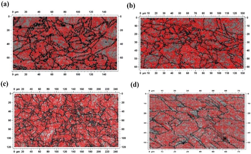
Figure 13. Inverse Pole figure (IPF) images using EBSD from specimens (a) A, (b) B, (c) C, and (d) D.
Figure 14. Images of high angle and low angle boundaries using EBSD from samples (a) A, (b) B, (c) C, and (d) D.
macroscopic decomposition of the grains, as shown in EBSD of the shear spinning specimens in different paths
in figure 13.
Figure 14 shows the high (black color) and low angle ( red color) boundaries in the shear spinning specimens
microstructure in different paths. Misorientations of 2° < θ < 15° have been assigned for defining low angle
boundaries, while 15° < θ misorientations are used for defining high angle boundaries.
The high to low angle boundaries (HGAB/LGAB) ratio in the shear spinning specimens for specimens A, B,
C and D is (0.34/0.66), (0.35/0.65), (0.37/0.63), and (0.35/0.65), respectively. Considering the frequency ratio
of high to low angle boundaries, it can be seen that this ratio is very close in all specimens and is the highest value
in specimen C. This could be due to the shear stresses in the opposite directions and successive passes on the T-N
plane. According to the EBSD images, during shear spinning the grain boundaries are formed along GNBs for
the fragmentation of the grains. In the shear spinning process, a great number of small sub-grains are
constructed. Several twins have also been observed in the deformed structure, although the number of twins is
small. Twins during deformation not only create independent slip systems but also cut large grains and turn
them into fine grains. This was also observed by Wang et al [21]. Cross-slip of dislocations and twins in materials
with low stacking fault energy (SFE) such as copper is one of the most significant mechanisms of deformation
8
Mater. Res. Express 8 (2021) 066521                                                                   S M J Hoseini et al

   Figure 15. Pole figure images of the shear spinning specimens (a) A, (b) B, (c) C, and (d) D.

[22]. During deformation processes, grain refinement involves different mechanisms . One of the major reasons
for grain refinement during cold work or warm work is continuous dynamic recrystallization [23, 24]. The
grains become fragmented by creating low angular dislocation boundaries due to deformation and,
subsequently, a gradual escalation in the grains misorientation occurs, which eventually leads to the conversion
of the grains to the normal boundaries [25]. According to Zhao et al [26], grain refinement can be achieved
through formation of micro-bands, formation of thin lattice structures in these microbands, and formation of
stretched grains in local shear bands. Xia et al [27] also stated that the reason for the evolution of microstructure
during shear spinning could be grain division. As a result, high plastic deformation of grain dislocations
gradually increases until cellular structures are formed. These cellular structures become sub-grains when
subjected to plastic deformation. These sub-grains form independent grains as the angle of misorientation
increases, and their boundaries become high angle boundaries. Also, the intersection of deformation bands
(DBs) can lead to the division of the grains into multiple sub-grains.
    According to the pole figures in figure 15, the shear spinning specimens in different directions have different
texture orientations and intensities. In specimen A, most of the texture is related to {123}⟨412⟩ orientation and
the copper texture is related to {112}⟨111⟩ orientation. In specimen B, the most texture was related to {4 4 11}
⟨11 11 8⟩ orientation, copper texture was {112}⟨111⟩ and texture {111}⟨110⟩, and in specimen C, most of the
texture was related to cubic texture with orientation {001}⟨100⟩ and orientations {011}⟨011⟩ and {112}⟨211⟩,
and in specimen D, most of the texture was related to brass texture with orientation {110} < 112} and textures
{211}⟨011⟩ and {110}⟨111⟩. In specimens B, C, and D, which have experienced the strain direction change
during shear spinning, the orientations have more shear texture components. This difference in texture and
intensity can be related to the difference in the formation paths and strain heterogeneity. Yan et al [28]
considered that for the FCC materials with low stacking fault energy (SFE), the shear banding was the chief
mechanism responsible for texture transfer from copper to brass at large deformations. This indicates that the
shear bands have also been developed by changing the strain-path. Yang et al [29] also stated that by changing the
direction of rotation in the power spinning process, more sliding systems may be activated in the specimens
which experienced the change in the strain direction. As a result, a more homogeneous texture is formed in these
specimens. Suwas et al [30] showed that in the copper rolling process, the components of copper texture, brass
and S {123} ⟨634⟩ are present and the copper and S components are weakened by changing the strain direction.
On the other hand, the brass texture components or those components that are close to it, {011} ⟨111⟩ or {011}

                                                          9
Mater. Res. Express 8 (2021) 066521 S M J Hoseini et al
Figure 16. Tensile test diagram of (a) the initial annealed specimen and tensile test diagram (b) In the direction of 0° (c) in the direction
of 45°, and (d) In the direction of 90° relative to the forming axis in shear spinning specimens in the A, B, C, and D paths.
⟨311⟩, are present in the copper metal texture with a change in the strain-path. The shear bands in
microstructural images of the rolled copper samples were also noticed. Upon two or more steps of changing the
forming direction, the shear bands direction relative to the unidirectional rolling specimen changed, and in both
directions the shear bands could be found. Wang et al [10] claimed that the shear strain was the cause of grain
refinement. Apart from that, a change in the load direction causes the GNBs intersection and creation of high
angle grain boundaries.
3.2. The tensile test
Tensile test was conducted on the initial annealed specimen and shear spinning parts in 4 different paths in three
directions of 0°, 45°, and 90°. The results of the tensile test are presented in figure 16. As can be observed in this
figure, shear spinning of the C11000 copper metal has augmented the strength and reduced elongation in all
three directions of 0°, 45°, and 90°. This is due to the increased work hardenning, increased density of
dislocations, and reduced grain size.
Figure 17 shows the comparative graph of tensile strength, and figure 18 shows a comparative diagram of the
percentage of elongation in three directions of 0°, 45°, and 90° relative to the forming axis in the initial annealed
and the shear spinning specimens in different directions. According to figure 17, it can be perceived that the
reduction in grain size due to the spinning process has increased the strength according to the Hall-Petch
relationship. The Hall-Petch relationship for bulk metals is:
1
sy = s0 + Kd - 2 (6)
where σy is the yield stress, σ0 is a lattice friction stress, and K is a constant of yielding, d is the average grain size
[31]. The maximum strength is related to specimen A and the lowest strength is related to specimen C. Also, the
strength in the direction of the main shear spinning axis in all specimens is the highest and in the direction of 90°
relative to the forming axis it is the lowest. This indicates that most of the grain refinement is done in the
direction of the shear spinning axis. Figure 18 shows the shear spinning process in copper has caused decrease
the elongation in all the tested paths. The highest value of elongation is attributed to specimen C and the lowest
value is related to specimen A. Also, due to the two changes in the direction of the forming of specimen C, it had
less strength and a higher elongation compared with specimens B and D, which experienced one change in the
direction of forming. According to a study by Ostafin et al [15], the strain-path change of plastic deformation in
the copper sheets destablizies the sub-structure and results in substantial microstructural changes along with
alterations in the distribution of grain orientation (crystalline texture). These alterations lead to variations of
mechanical and plastic properties and suppression of deformation twinning. Based on their obtained results, the
strain-path change in the copper sheets will lead to the formation of appropriate textures and decrease
detrimental textures. The strain-path change in specimens B, C, and D reduced the grain size. We expect that
according to Hall-Petch relation the finer grain size should induce an escalation of strength. At the same time, a
10Mater. Res. Express 8 (2021) 066521 S M J Hoseini et al
Figure 17. Comparative graph of tensile strength in the three directions of 0°, 45°, and 90° relative to the forming axis in the initial
annealed and the shear spinning specimens in different paths.
Figure 18. Comparative graph of elongation in the three directions of 0°, 45°, and 90° relative to the forming axis in the initial
annealed and the shear spinning specimens in different paths.
strain-path change in shear spinning is followed by the reduction of strength and enhancement of elongation in
relation to unidirectional shear spinning. This could be due to the creation of a weaker crystalline texture as well
as dynamic recrystallization as a consequence of the strain-path alteration. This has also been observed in Zhang
et al [32] and Rout et al [14].
The ΔR and Rm anisotropy values in the shear spinning specimens were calculated in line with the obtained
strain in the transverse and longitudinal directions of the samples of tensile test , as shown by the diagram in
figure 19.
According to the values obtained from ΔR and Rm related to the initial annealed and the shear spinning
specimens and also the diagrams of figure 19, we can see that anisotropy increased by shear spinning and the ΔR
and Rm values decrease as the strain direction changes. Thus, alteration in the deformation direction during
shear spinning results in the reduction of anisotropy. Similar to the results of Goli et al [33] study, the strain
orientation change has been an efficient technique for decreasing the anisotropy of mechanical properties of the
C11000 alloy. These results comply with those reported by other researchers such as Rout et al [14], Wronski et al
[34], etc. So, the strain-path change in the C11000 alloy can result in the formation of a shell with relatively more
isotropic properties in different directions in comparison with unidirectional shear spinning.
3.3. Micro-hardness evaluation
Micro-hardness assessment was done on the shear spinning parts in different paths on the three planes of R-T,
R-N, and T-N figure 20 represents the microhardness test results in the form of a diagram. Considering that
micro-hardness of the initial annealed specimen is equal to 50 Vickers, it is revealed that by performing the shear
spinning process in different paths in all three planes, the hardness value has increased drastically. This increase
in hardness is the increase in dislocations density, more refined grains, and shorter grain boundary distance.
Also, specimen A, which has no change in the direction of rotation of shear spinning, has the highest amount of
11Mater. Res. Express 8 (2021) 066521 S M J Hoseini et al
Figure 19. Diagram of anisotropy values in the initial annealed and the shear spinning specimens in different paths.
Figure 20. Comparative diagram of micro-hardness in the R-T, R-N, and T-N planes in the initial annealed and the shear spinning
specimens in different paths.
micro-hardness. The lowest amount of micro-hardness is related to specimen C with two changes of direction of
rotation. By changing the direction of rotation in specimens B, C, and D, micro-hardness is reduced. This
reduction in micro-hardness is due to more grain refinement, more active slip planes, and less dislocations
density.
4. Conclusion
In this research, specimens of C11000 copper were subjected to the shear spinning process in different
directions. The following results were obtained:
1. Shear spinning has caused the grains elongation in the axial direction and increased the grain length in the
circumferential direction. However, in the axial direction this elongation of the grains is greater compared with
the circumferential direction. Alteration of strain-path in the shear spinning specimens has somewhat resulted
in more grain refinement and a higher percentage of high-angle boundaries. This is the change in the shear
strains direction and subsequent existence of the shear bands in the opposite directions and, as a result, the
division of the grains.
2. Mechanical properties of the shear spinning specimens in different paths improved compared to the
original annealed specimen. Strength and hardness increased, and the elongation decreased. In the shear
spinning specimens in different paths, in the case of specimen C, which had more strain-path change, strength
was reduced by 9% to 11%, hardness by 1 to 9% less, and elongation by 7% to 37% higher than the specimen
without path change.
3. The shear spinning specimens in different paths have different orientations and texture intensities. In the
specimen without strain-path change (specimen A), most of the texture is related to the {123}⟨412⟩ orientation,
and the copper texture is related to the {112}⟨111⟩ orientation. On the other hand, in the shear spinning
12Mater. Res. Express 8 (2021) 066521 S M J Hoseini et al
specimens in other paths, textures with {001} ⟨100⟩, {011} ⟨011⟩, {211} ⟨011⟩ orientations and brass texture
with {110} ⟨112⟩ orientation are strengthened.
4. The shear spinning on copper samples increased anisotropy compared to the initial annealed sample. Due
to the change in texture and mechanical properties, the strain-path change in the shear spinning process has
reduced the anisotropy in the C11000 alloy relative to unidirectional shear spinning sample.
Acknowledgments
The authors are thankful to ‘Ideh Pardazan Vatan’ Company for helping in this work by making the shear
spinning parts.
Data availability statement
The data generated and/or analysed during the current study are not publicly available for legal/ethical reasons
but are available from the corresponding author on reasonable request.
ORCID iDs
Seyed Mohammad Javad Hoseini https://orcid.org/0000-0002-0450-026X
References
[1] Davis J R, Henry S D, Sanders B R, Hrivnak N, Kinson J A and Scott W W 2001 ASM specialty handbook copper and copper alloys (USA:
ASM International) p 3
[2] Yanushkevich Z, Belyakov A, Kaibyshev R, Haase C and Molodov D A 2016 Deformation and recrystallization textures in a high-Mn
steel subjected to large strain cold rolling TMS(ReX&GG 2016) (Pittsburgh: Springer) pp 147–52
[3] Pawar P, Pagar A, Shah A and Yevale S 2017 Review on spinning attachment to Lathe machine International Journal on Recent and
Innovation Trends in Computing and Communication Abbreviation 5 1280–91
[4] Radović L, Nikačević M and Jordović B 2012 Deformation behavior and microstructure evolution of AlMg6Mn alloy during shear
spinning Transactions of Nonferrous Metals Society of China 22 991–1000
[5] Wong C C, Dean T and Lin J 2003 A review of spinning, shear forming and flow forming processes Int. J. Mach. Tools Manuf 43
1419–35
[6] Hagan E and Jeswiet J 2003 A review of conventional and modern single-point sheet metal forming methods Proc. Inst. Mech. Eng. Part
B J. Eng. Manuf. 217 213–25
[7] Hosford W F and Caddell R M 2007 Metal Forming Mechanics And Metallurgy 3rd ed (New York: Cambridge University Press)
pp 271–2
[8] Sivanandini M, Dhami S and Pabla B 2012 Flow forming of tubes-a review International Journal of Scientific and Engineering Research 3
1–11
[9] Zhan M, Wang X and Long H 2016 Mechanism of grain refinement of aluminum alloy in shear spinning under different deviation
ratios Mater. Des. 108 207–16
[10] Wang X X, Zhan M, Fu M W, Guo J, Xu R Q and Lei X P 2017 A unique spinning method for grain refinement:repetitive shear spinning
Procedia Engineering 207 1725–30
[11] Guillot M, McCormack T, Tuffs M, Rosochowsk A, Halliday S and Blackwell P 2017 Shear forming of 304L stainless steel—
microstructural aspects Procedia Engineering 207 1719–24
[12] Suwas S and Gurao N 2014 Development of microstructures and textures by cross rolling Comprehensive Materials Processing 3 81–106
[13] Gurao N, Sethuraman S and Suwas S 2011 Effect of strain path change on the evolution of texture and microstructure during rolling of
copper and nickel Mater. Sci. Eng. A 528 7739–50
[14] Rout M, Pal S K and Singh S B 2015 Cross rolling: a metal forming process Modern Manufacturing Engineering, Materials Forming ed
J P Davim (Switzerland: Springer International Publishing) pp 41–64
[15] Ostafin M, Pospiech J and Schwarzer R A 2005 Microstructure and texture in copper sheets after reverse and cross rolling Solid State
Phenomena 105 309–14
[16] Suwas S and Singh A K 2003 Role of strain path change in texture development Mater. Sci. Eng. A 356 368–71
[17] Gur C H and Arda E B 2003 Effect of tube spinning and subsequent heat treatments on strength, microstructure and residual stress state
of AISI/SAE type 4140 steel Mater. Sci. Technol. 19 1590–4
[18] Liu Q and Hansen N 1998 Macroscopic and microscopic subdivision of a cold-rolled aluminum single crystal of cubic orientation
Royal Society 454 2555–91
[19] Xu Y, Jiao H, Qiu W, Misra R D K and Li J 2018 Effect of cold rolling process on microstructure, texture and properties of strip cast Fe-
2.6%Si steel Materials 1161 1–12
[20] Kim C, Jung S Y and Choi J C 2003 A lower upper-bound solution for shear spinning of cones Int. J. Mech. Sci. 45 1893–911
[21] Wang X, Gao P, Zhan M, Yang K, Dong Y and Li Y 2020 Development of microstructural inhomogeneity in multi-pass flow forming of
TA15 alloy cylindrical parts Chin. J. Aeronaut. 33 2088–97
[22] Haghshenas M and Klassen R J 2015 Mechanical characterization of flow formed FCC alloys Mater. Sci. Eng. A 641 249–55
[23] Sakai T, Belyakov A, Kaibyshev R, Miura H and Jonas J 2014 Dynamic and post-dynamic recrystallization under hot, cold and severe
plastic deformation conditions Prog. Mater. Sci. 60 130–207
13Mater. Res. Express 8 (2021) 066521 S M J Hoseini et al
[24] Bacca M, Hayhurst D and McMeeking R M 2015 Continuous dynamic recrystallization during severe plastic deformation Mech. Mater.
90 148–56
[25] Humphreys F and Hatherly M 2004 Recrystallization and related annealing phenomena 2nd ed (Oxford: Elsevier) pp 11–60
[26] Zhao H, Ni S, Song M, Xiong X, Liang X and Li H 2015 Grain refinement via formation and subdivision of microbands and thin laths
structures in cold-rolled hafnium Mater. Sci. Eng. A 645 328–32
[27] Xia Q, Xiao G, Long H, Cheng X and Yang B 2014 A study of manufacturing tubes with nano/ultrafine grain structure by stagger
spinning Materials Design 59 516–523
[28] Yan H, Zhao X, Jia N, Zheng Y and He T 2014 Influence of shear banding on the formation of brass-type textures in polycrystalline fcc
metals with low stacking fault energy Mater. Sci. Technol. 30 408–16
[29] Yang Z, Xu W, Wu H, Wan X, Chen Y, Shan D and Guo B 2020 Enhancing hoop strength of titanium alloy tube by cross spinning Int. J.
Mach. Tools Manuf 152 103530
[30] Suwas S, Singh A K, Rao K N and Singh T 2002 Effect of modes of rolling on evolution of the texture in pure copper and some copper-
base alloys, Part I: Rolling texture Carl Hanser Verlag, MuÈnchen Z. Metallkd. 93 918–27
[31] Balasubramanian N and Langdon T G 2016 The Strength–Grain Size Relationship in Ultrafine-Grained Metals Metall. Mater. Trans. A
47 5827–38
[32] Zhang H, Huang G, Roven H J, Wang L and Pan F 2013 Influence of different rolling routes on the microstructure evolution and
properties of AZ31 magnesium alloy sheets Mater. Des. 50 667–73
[33] Goli F and Jamaati R 2019 Effect of strain path during cold rolling on the microstructure, texture, and mechanical properties of AA2024
aluminum alloy Mater. Res. Express 6 066514
[34] Wronski S, Wrobel M, Baczmanski A and Wierzbanowski K 2013 Effects of cross-rolling on residual stress, texture and plastic
anisotropy in f.c.c. and b.c.c. metals Mater. Charact. 77 116–26
14You can also read