HARDIEGROOVE LINING INSTALLATION MANUAL - JULY 2021 NEW ZEALAND
←
→
Page content transcription
If your browser does not render page correctly, please read the page content below
Hardie Groove
                                    ™

          jameshardie.co.nz
                                      Lining

Installation Manual
July 2021 New Zealand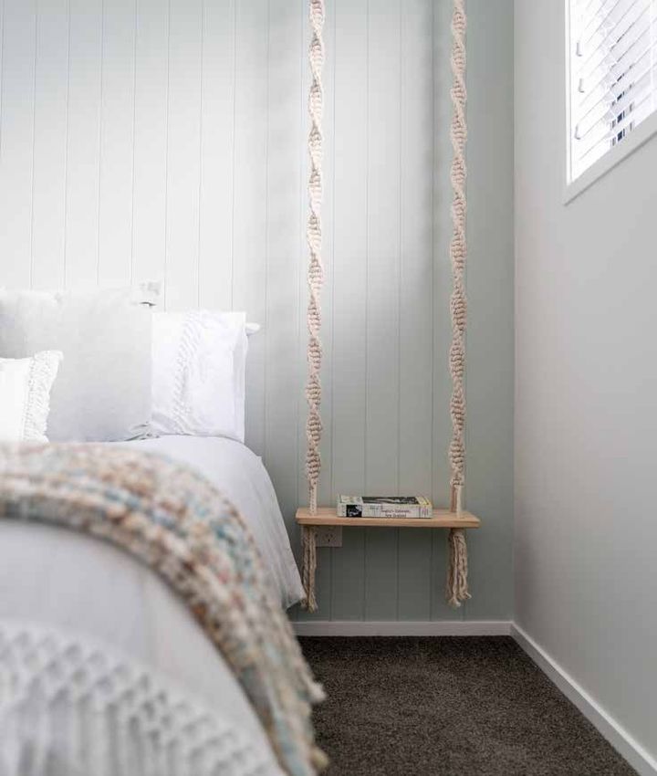
We value your feedback!
    To continue with the development of our products and systems, we value your
    input. Please send any suggestions, including your name, contact details, and
    relevant sketches to:
    Ask James Hardie™
    literaturefeedback@jameshardie.co.nz

    Make sure your information is up to date
    When specifying or installing Hardie™ fibre cement products, ensure that you have
    the current manual. Additional installation information, warranties and warnings
    are available at www.jameshardie.co.nz or Ask James Hardie™ on 0800 808 868.

2   Hardie™ Groove Lining Installation Manual | July 2021 New Zealand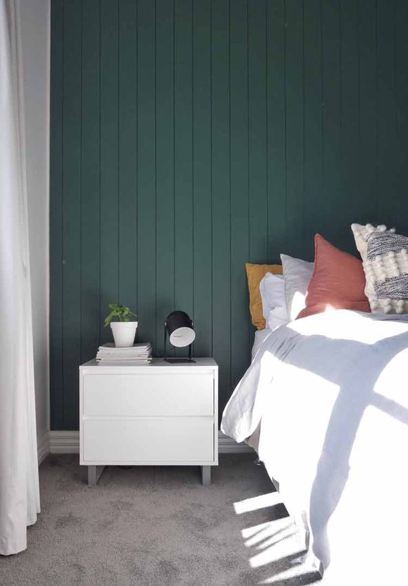
Contents

1     Introduction	                       4     5	Jointing and Corners	                                             22
                                                 5.1   Butt Joints	                                                     22
2     Safe Working Practices	             7     5.2   Corners	                                                         24

2.1 Storage and Delivery 	                 9
2.2 	Tips for Safe and Easy Handling of
                                                 6 	 Product Information	                                            27
      Hardie™ Groove Lining	              10    6.1   General	                                                         27
                                                 6.2   Product Mass	                                                    27
3     Framing	                            10    6.3   Durability	                                                      27
                                                 6.4   Fire Properties	                                                 27
3.1   General	                            10
3.2   Timber	                             10
3.3   Steel	                               11
                                                 Product Warranty                                                     31
3.4   Preparation	                         11

4 Installation	                           12
4.1   Sheet Layout	                        12
4.2   Fasteners	                           12
4.3   Fixing To Walls	                    13
4.4   Full Sheet Fixing	                  16
4.5   Dado Height Fixing	                 18
4.6   Fixing Over Plasterboard Lining	    20
4.7   Fixing to Ceilings and Soffits	     20
4.8   Fixing to Masonry Substrates	        21

                                                         Hardie™ Groove Lining Installation Manual | July 2021 New Zealand   3
1 Introduction
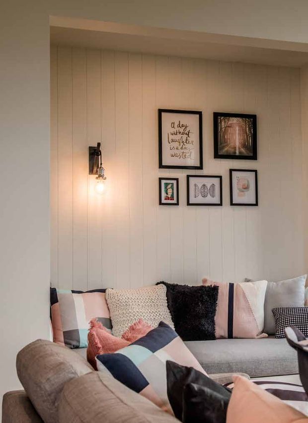
Hardie™ Groove Lining combines the appearance of traditional timber tongue and groove wall panelling with the
benefits of modern fibre cement.
Because the baseboard is Hardie™ fibre cement, it’s resistant to fire, rot resistant and resistant to moisture damage
when installed and maintained as directed.
Hardie™ Groove Lining has decorative v-shaped grooves carved into the front face of the 7.5mm sheet, and is
sanded, ready to be painted in any colour.
Hardie™ Groove Lining can be fixed to the full height of the wall or at dado height to create a decorative, hard-
wearing, impact resistant lining in hallways and to withstand the toughest treatment in family rooms, rumpus
rooms, laundries and bathrooms (not suitable for shower areas).
Hardie™ Groove Lining is also ideal for use in ceilings, either to add interest to a modern design, or to create
historical detail on a renovation project.
The main features of Hardie™ Groove Lining are:
• Durable internal lining, soffit and ceiling sheet.
• Creates suitable surface for paint finish.
• Sheet edges have a ‘half groove’ to achieve concealed sheet joints.
• Reliable impact resistant decorative lining. Ideal for wall lining where walls are prone to damage.
• Resistance to damage from moisture making it ideal for bathrooms, laundries and kitchens.
• Joints won’t pull or shift apart.
• Authentic v-shaped grooves replicate traditional tongue and groove look and style.
• Ideal as feature wall to dado height.
The specifier or other responsible party for the project must ensure the information and details in this guide are
appropriate for the intended application and specific design and detailing is undertaken for areas which fall
outside the scope of this documentation.
Make sure your information is up to date
When specifying or installing Hardie™ fibre cement products, ensure you have the current manual. If you’re
not sure you do, or if you need more information, visit www.jameshardie.co.nz or Ask James Hardie™ on
0800 808 868.
Hardie™ Groove Lining is only for use in internal applications.
For use externally on eaves and soffits refer to the Eaves and Soffits Installation Manual by James Hardie.
James Hardie conducts stringent quality checks to ensure that any product manufactured falls within our quality
spectrum. It is the responsibility of the builder to ensure that the product meets their aesthetic expectations before
installation. James Hardie will not be responsible for rectifying obvious aesthetic surface variations following
installation. James Hardie will only offer a replacement product if Hardie™ Groove Lining supplied are found to be
out of its manufacturing specification.
4 Hardie™ Groove Lining Installation Manual | July 2021 New ZealandTable 1
Product Description Description
Hardie™ Groove Lining is a
v-grooved internal lining board
with the look of timber and the
durability of fibre cement.
5mm
Individual batten widths are
100mm 100mm
2.5
mm Sheet sizes:
2400mm x 1200mm x 7.5mm
Half groove edge Product code 400246
2700mm x 1200mm x 7.5mm
Product code 400245
Note: All dimensions and masses provided are approximate only and are subject to manufacturing tolerances.
Table 2
Product/Accessories/Tools supplied by James Hardie
Product Description Code Product Description Code
Hardie Blade Saw
™
300660 FibreTEKS Screw
®
1000/box
Blade 184mm diameter, For fastening to 0.75mm 303840
poly diamond blade, to 1.0mm BMT steel
for fast, clean cutting of frames.
Hardie™ fibre cement.
Class 3 finish. Length:
30mm x 9g
® denotes a registered
mark of Buildex®
Hardie™ Base Coat Hardie™ Drive Screw 100/jar
For finishing fastener s/s 316 300928
heads. 30mm x 7g
Volume: 4kg Pail 304490
15kg Bag 304491
Soffit Scotia Mould 2 300916 Villadrive™ Wood Screw 100/jar
pcs. Envirodrab coating. 300992
(base and cap) Length: 30mm x 6g 5kg/box
2400mm
300993
1000
collated
300994
Hardie™ Knife 305926
Scoring tool for easy
cutting.
Hardie™ Groove Lining Installation Manual | July 2021 New Zealand 5Table 3
Product/Accessories/Tools not supplied by James Hardie
James Hardie recommends the following products for use in conjunction with its Hardie™ Groove Lining. James
Hardie does not supply these products and does not provide a warranty for their use. Please contact the
component manufacturer for information on their warranties and further information on their products.
Hardie™ Flex nails Fibreshear
40 x 2.8mm galvanised or stainless Electric cutting tool.
steel 316 fibre cement nails for
fastening to timber.
Adhesive Sealant Brad Nail
Sika® Sikaflex® 11FC, Bostik® Seal N ND 50
Flex-1, Fuller™ Max Bond™, Selleys® To be used in conjuction with 6mm
Liquid Nails bead of adhesive on a stud/nogs.
Only suitable for internal walls.
6 Hardie™ Groove Lining Installation Manual | July 2021 New Zealand2 Safe Working Practices
WARNING - DO NOT BREATHE DUST AND CUT ONLY IN WELL VENTILATED AREA
Hardie™ fibre cement products contain sand, a source of respirable crystalline silica. May cause cancer if
dust from product is inhaled. Causes damage to lungs and respiratory system through prolonged or repeated
inhalation of dust from product.
Intact fibre cement products are not expected to result in any adverse toxic effects. The hazard associated with
fibre cement arises from the respirable crystalline silica present in dust generated by activities such as cutting,
rebating, drilling, routing, sawing, crushing, or otherwise abrading fibre cement, and when cleaning up, disposing
of or moving dust.
When doing any of these activities in a manner that generates dust, follow James Hardie’s instructions and best
practices to reduce or limit the release of dust.
If using a dust mask or respirator, use an AS/NZS 1716 P1 filter and refer to Australian/New Zealand Standard
1715:2009 Selection, Use and Maintenance of Respiratory Protective Equipment for more extensive guidance and
more options for selecting respirators for workplaces. For further information, refer to our installation instructions
and Safety Data Sheets available at www.jameshardie.co.nz.
FAILURE TO ADHERE TO OUR WARNINGS, SAFETY DATA SHEETS, AND INSTALLATION INSTRUCTIONS MAY LEAD
TO SERIOUS PERSONAL INJURY OR DEATH.
Crystalline Silica is
• Commonly known as sand or quartz
• F
ound in many building products e.g. concrete, bricks, grout, wallboard, ceramic tiles, and all fibre cement
materials
Why is Crystalline Silica a health hazard?
• S
ilica can be breathed deep into the lungs when present in the air as a very fine (respirable) dust
• E
xposure to silica dust without taking the appropriate safety measures to minimise the amount being breathed
in, can lead to a potentially fatal lung disease – silicosis – and has also been linked with other diseases including
cancer. Some studies suggest that smoking may increase these risks
• The most hazardous dust is the dust you cannot see!
When is Crystalline Silica a health hazard?
• It’s dangerous to health if safety protocols to control dust are not followed when cutting, drilling or rebating a
product containing crystalline silica
• P
roducts containing silica are harmless if intact (e.g. an un-cut sheet of wall board)
Hardie™ Groove Lining Installation Manual | July 2021 New Zealand 7Avoid breathing in crystalline silica dust
Safe working practices
N
EVER use a power saw indoors or in a poorly ventilated area
N
EVER dry sweep
ALWAYS use M Class or higher vacuum or damp down dust before sweeping up
N
EVER use grinders
LWAYS use a dust reducing circular saw equipped with a sawblade specifically designed to minimise dust
A
creation when cutting fibre cement – preferably a sawblade that carries the Hardie™ Blade name or one with
at least equivalent performance – connected to an M Class or higher vacuum
Before cutting warn others in the area to avoid dust
ALWAYS follow tool manufacturers’ safety recommendations
ALWAYS expose only the minimum required depth of blade for the thickness of fibre cement to be cut
LWAYS wear a properly-fitted, approved dust mask or respirator P1 or higher in accordance with applicable
A
government regulations and manufacturer instructions
C
onsider rotating personnel across cutting tasks to further limit respirable silica exposures.
Use one of the following for cutting:
Best
• Hardie™ Knife
• Hand guillotine
• Fibreshear
Better
Dust reducing circular saw equipped with Hardie™ Blade Saw Blade and connected to a M Class or higher
vacuum.
When cutting outdoors
M
ake sure you work in a well ventilated area
P
osition cutting station so wind will blow dust away from yourself and others in the working area
ut products with either a Hardie™ Knife or fibre cement shears or, when not feasible, a Hardie™ Blade Saw
C
Blade (or equivalent) and a dust reducing circular saw connected to a M Class or higher vacuum
When sawing, sanding, rebating, drilling or machining fibre cement products, always:
- W
ear your P1 or higher mask (correctly fitted in accordance with manufacturers’ instructions), ask others to
do the same.
- K
eep persons on site at least 2 metres and as far as practicable away from the cutting station while the saw
is in operation
- If you are not clean shaven, then use a powered air respirator with a loose-fitting head top
- Wear safety glasses
- Wear hearing protection
- When others are close by, ask them to do the same
ake sure you clean up BUT never dry sweep. Always hose down with water/wet wipe or use an M Class or
M
higher vacuum
8 Hardie™ Groove Lining Installation Manual | July 2021 New ZealandWhen cutting indoors
N
ever cut using a circular saw indoors
P
osition cutting station in a well ventilated area
Cut ONLY using a Hardie™ Knife, hand guillotine or fibreshears
(manual, electric or pneumatic)
ake sure you clean up BUT never dry sweep. Always hose
M
down with water/wet wipe or use an M Class or higher
vacuum
Working instructions
Hardie™ Blade Saw Blade
The Hardie™ Blade Saw Blade used with a dust-reducing saw is
ideal for fast, clean cutting of Hardie™ fibre cement products. A
dust-reducing saw uses a dust collector connected to a M Class or
higher vacuum. When sawing, clamp a straight edge to the sheet
as a guide and run the saw base plate along the straight edge
when making the cut.
Hole forming
For smooth clean cut circular holes:
• Mark the centre of the hole on the sheet
• P
re-drill a ‘pilot’ hole
• U
sing the pilot hole as a guide, cut the hole to the appropriate diameter with a hole saw fitted to a heavy duty
electric drill
For irregular holes:
• S
mall rectangular or circular holes can be cut by drilling a series of small holes around the perimeter of the hole
then tapping out the waste piece from the sheet face
• Tap carefully to avoid damage to sheets, ensuring that the sheet edges are properly supported
2.1 Storage and delivery
Keeping products and people safe
Off loading
Hardie™ fibre cement products should be off-loaded carefully by hand or by forklift
Hardie™ fibre cement products should not be rolled or dumped off a truck during the delivery to the jobsite
Storage
Hardie™ fibre cement products should be stored:
In their original packaging
Hardie™ Groove Lining Installation Manual | July 2021 New Zealand 9 U
nder cover where possible or otherwise protected with a waterproof covering to keep products dry
O
ff the ground – either on a pallet or adequately supported on timber or other spacers
Flat so as to minimise bending
Hardie™ fibre cement products must not be stored:
Directly on the ground
In the open air exposed to the elements
James Hardie is not responsible for damage due to improper storage and handling.
2.2 Tips for Safe and Easy Handling of Hardie™ Groove Lining
Carry with two people
Hold near each end and on edge
E
xercise care when handling sheet products to avoid damaging the edges/corners
3 Framing
3.1 General
Hardie™ Groove Lining can be fixed to either timber or light gauge domestic type steel framing. The framing used
must comply with the relevant building regulations and standards and the requirements of this manual.
Note: Hardie™ Groove Lining must not be used in shower areas.
3.2 Timber
Timber framing must comply with the durability requirements of Clause ‘B2’ of the NZBC. Timber must be treated
as per the requirements of the NZS 3602.
Timber framing sizes and set out must satisfy the minimum requirements of NZS 3604 and this installation guide.
The minimum stud width of 35mm may be used. However, where butt jointing is used the minimum stud width is
45mm at the joint. See Figure 13.
Reference NZS 3604 ‘Timber-framed Buildings’.
10 Hardie™ Groove Lining Installation Manual | July 2021 New Zealand3.3 Steel
The minimum size for steel stud framing should be 64mm deep x 0.55mm base metal thickness (BMT). Steel
framing shall comply with NASH 3405 Steel Framed Buildings. Steel sections shall be galvanised or zinc coated of
0.55mm — 1.6mm BMT. Studs must not be less than 38mm wide at butt joints.
Figure 1: Frame straightness
3.4 Preparation
Ensure frame is square and work from a central datum line. Frames must be straight and true to provide a flush
face to receive the sheeting.
A suggested maximum tolerance of between 3mm and 4mm in any 3000mm length of frame will give best
results. Hardie™ Groove Lining will not straighten excessively warped or distorted frames and any warping may
still be visible after the internal lining is installed.
Hardie™ Groove Lining Installation Manual | July 2021 New Zealand 114 Installation
4.1 Sheet Layout
Hardie™ Groove Lining is usually fixed vertically. Sheet joints must coincide with the centre line of the framing
member.
The long edges of the sheet have a unique half groove, which achieves a concealed joint.
Where fixing half height sheets as a dado wall, provide a row of noggings to allow for fastening of the sheet edge.
When fixing around window openings, best practice would be to align the sheet joints with the window jamb.
4.2 Fasteners
Fasteners must have the appropriate level of durability required for the intended project.
Fasteners must be fully compatible with all other material that they are in contact with to ensure the durability and
integrity of the assembly.
• On timber frame use Villadrive™ screws 30mm x 6g or Hardie™ Drive stainless steel screws for quick installation
of Hardie™ Groove Lining.
• Alternatively the Hardie™ Groove Lining can be fixed with 40 x 2.8mm Hardie™ Flex nails or ND 50 brad nails.
• For fixing Hardie™ Groove Lining to 0.55 – 1.0mm BMT steel framing, use 30mm Buildex® FibreTEKS collated
screws.
Nails must be finished flush (Figure 2). Screws can be driven 0.5mm below the sheet surface to achieve the
required finish level (Figure 2). In steel framing the fasteners should be driven as close as possible to the stud
corners to avoid deflection of the stud flange, see Figure 3.
Figure 2: Fastener depth
Drive screw 0.5mm
below sheet surface
Flush nailing Unacceptable: Unacceptable:
HardieFlex nail under driven over driven
and Brad nail
12 Hardie™ Groove Lining Installation Manual | July 2021 New ZealandFigure 3: Screw fastening
NOTE:
By installing
the sheets in this
sequence a flush
outside surface is
maintained.
STEP 1 STEP 2
Fix sheet to the Fix the next sheet to
open side of flange the web side of the stud
Note: Do not place nails or screws within 100mm of the adhesive daubs.
4.3 Fixing to Walls
Step 1
Place 6.0mm off-cut packers along floor as temporary support for sheets.
This allows provision for frame movement. Put sheet in place as shown.
Step 2
Fix sheet starting from the centre of sheet and working outwards to avoid any druminess. For fastener spacings
refer to Figures 6 and 8 for full height and dado height walls respectively.
Final step
Fix remaining sheets in similar sequence.
Hardie™ Groove Lining Installation Manual | July 2021 New Zealand 13Figure 4: Sheet installation
Figure 5: Sheet fixing
14 Hardie™ Groove Lining Installation Manual | July 2021 New Zealand4.4 Full Sheet Fixing
When fixing full sheets of Hardie™ Groove Lining to framed walls, fasten sheets as shown in Figure 6. Sheet butt
joints must coincide with the centre line of framing members.
Figure 6: Full sheet fixing
HardieGroove Lining 6mm gap
200mm
max.
300mm
max.
12mm min.
200mm from edge
max.
1200mm
min.
6mm
gap
50mm min. 600mm
at corners max.
Hardie™ Groove Lining Installation Manual | July 2021 New Zealand 15Notes:
1. To reduce the number of visible fixings the centre of the sheet can be fixed with adhesive. See Figure 8 and 9 for details.
2. Hardie™ Groove Lining can also be fixed using brad nails in conjunction with adhesives to reduce visible fixings.
Figure 7: Brad nail fixing
16 Hardie™ Groove Lining Installation Manual | July 2021 New Zealand4.5 Dado Height Fixing
Hardie™ Groove Lining may be installed to half the wall height to create a dado appearance. Ensure top of sheet
is fixed to an in-line row of noggings as shown in Figure 8 and 9.
Figure 8: Dado height fixing with brads
Villaboard™ Lining
Hardie™ Groove Lining Installation Manual | July 2021 New Zealand 17Figure 9: Dado height fixing with screws
Villaboard™ Lining
18 Hardie™ Groove Lining Installation Manual | July 2021 New Zealand4.6 Fixing Over Plasterboard Lining
Hardie™ Groove Lining can be fixed over an existing plasterboard lining. The sheet must be fixed with minimum
50mm nail or a screw 40mm x 8g.
4.7 Fixing To Ceilings and Soffits
For Fixing Hardie™ Groove Lining to soffit/ceiling, refer to Eaves and Soffit Linings Installation Manual for further
detailed information.
In ceiling applications Hardie™ Groove Lining can be fixed either parallel or perpendicular to framing. See Figure
10.
Figure 10: Along joists Across joists
50mm min.
at corners
50mm min.
at corners
12mm min.
from edge
12mm min.
from edge
200mm 250mm
max. max.
around
edges
600mm 200mm
max centres. max.
around
edges
250mm
max.
600mm
max centres.
Notes:
1. Fastener fixing method is shown, however, fastener/adhesive fixing method may also be used. See Figure 8 and 9.
2. In ceiling applications do not fix sheets to the bottom chord of roof trusses. Instead, fix to timber battens or metal furring
channels.
3. Do not use brad nails in ceiling/soffit applications.
4. When butt jointing short ends of Hardie™ Groove Lining in ceiling/soffit applications, the short edges must be cut square
and have chamfer formed.
Hardie™ Groove Lining Installation Manual | July 2021 New Zealand 194.8 Fixing To Masonry Substrates
Hardie™ Groove Lining can be installed over masonry substrates. Refer Figure 11.
Figure 11: Batten/furring channel
Masonry Fastener
6mm gap
200mm
max. HardieGroove
600mm
max. Lining
1200mm max.
200mm
max.
12mm min.
from edge
50mm min. 6mm
from corners gap 200mm
max. centres
35mm thick x 45mm wide
timber batten/steel
furring channel fixed to
wall with suitable fasteners
or anchor clips.
20 Hardie™ Groove Lining Installation Manual | July 2021 New Zealand5
Jointing and Corners
5.1 Butt Joints
Hardie™ Groove Lining is butt jointed by joining two factory finished half groove sheet edges on stud. This creates
a grooved look consistent with the rest of the sheet. See Figures 12 and 13.
Figure 12: Butt joint
Hardie™ Groove Lining Installation Manual | July 2021 New Zealand 21Figure 13: Butt joint 22 Hardie™ Groove Lining Installation Manual | July 2021 New Zealand
5.2 Corners
External and internal corners are created by butting sheet edges as shown, see Figures 14 to 16. If sheets need
to be trimmed, for best appearance place the cut sheet edge into corner first ensuring that it is hidden by the
overlapping sheet. Alternatively a suitable timber moulding may be used.

 Figure 14: Corner details

                HardieGroove
                Lining

                  40 x 2.8mm
                  HardieFlex™
                  nail

                                                                   Hardie™ Groove Lining Installation Manual | July 2021 New Zealand   23
Figure 15: External corner 24 Hardie™ Groove Lining Installation Manual | July 2021 New Zealand
Figure 16: Internal corner

                             Hardie™ Groove Lining Installation Manual | July 2021 New Zealand   25
6 P roduct Information
6.1 General
Hardie™ Groove Lining is a cellulose fibre reinforced cement building product. The basic composition is Portland
cement, ground sand, cellulose fibre and water.
Hardie™ Groove Lining is manufactured to AS/NZS 2908.2 ‘Cellulose-Cement Products Part 2: Flat Sheets’ (ISO
8336 ‘Fibre Cement Flat Sheets’).
Hardie™ Groove Lining is classified Type B, Category 3 in accordance with AS/NZS 2908.2 ‘Cellulose-Cement
Products’.
For Safety Data Sheets (SDS) visit www.jameshardie.co.nz or Ask James Hardie™ on 0800 808 868.
6.2 Product Mass
Based on equilibrium moisture content the approximate mass of Hardie™ Groove Lining is 10.44kg/m2.
6.3 Durability
Resistance to moisture/rotting
Hardie™ Groove Lining has demonstrated resistance to permanent moisture induced deterioration (rotting) and
has passed the following tests in accordance with AS/NZS 2908.2:
• Heat rain (Clause 6.5)
• Water permeability (Clause 8.2.2)
• Warm water (Clause 8.2.4)
• Soak dry (Clause 8.2.5)
6.4 Fire Properties
Maximum service temperature for the Hardie™ Groove Lining is 60ºC.
Hardie™ Groove Lining sheet has been tested for heat release rate as per AS/NZS 3837 and the product has a
Heat Release Rate below 50 kw/m2.
Hardie™ Groove Lining has a ‘Group Number’ classification of 1-S as per the requirements of clause C of the NZBC.
26 Hardie™ Groove Lining Installation Manual | July 2021 New ZealandHardie Groove ™
Lining
Product Warranty
James Hardie New Zealand Limited (“James Hardie”) warrants to the first purchaser of the Product for a period
of 15 years from the date of purchase that the Hardie™ Groove Lining (the “Product”), will be free from defects
due to defective factory workmanship or materials and, subject to compliance with the conditions below, will be
resistant to cracking, rotting, fire and damage from termite attacks to the extent set out in James Hardie’s relevant
published literature current at the time of installation. James Hardie warrants for a period of 15 years from the date
of purchase that the accessories supplied by James Hardie to be used in conjunction with the Product will be free
from defects due to defective factory workmanship or materials.
Nothing in this document shall exclude or modify any legal rights a customer may have under the Consumer
Guarantees Act or otherwise which cannot be excluded or modified at law.
CONDITIONS OF WARRANTY
The warranty is strictly subject to the following conditions:
(a) James Hardie will not be liable for breach of warranty unless the claimant provides proof of purchase and
makes a written claim either within 30 days after the defect would have become reasonably apparent
or, if the defect was reasonably apparent prior to installation, then the claim must be made prior to
installation;
(b) this warranty is not transferable;
(c) the Product must be installed and maintained strictly in accordance with the relevant James Hardie
literature current at the time of installation and must be installed in conjunction with the components or
products specified in the literature. To obtain copies of such literature please contact ‘Ask James Hardie™
0800 808 868’. Further, all other products, including coating and jointing systems, applied to or used in
conjunction with the Product must be applied or installed and maintained strictly in accordance with the
relevant manufacturer’s instructions and good trade practice;
(d) the project must be designed and constructed in strict compliance with all relevant provisions of the
current NZBC, regulations and standards;
(e) the claimant’s sole remedy for breach of warranty is (at James Hardie’s option) that James Hardie will
either supply replacement product, rectify the affected product or pay for the cost of the replacement or
rectification of the affected product;
(f) James Hardie will not be liable for any losses or damages (whether direct or indirect) including property
damage or personal injury, consequential loss, economic loss or loss of profits, arising in contract or
negligence or howsoever arising. Without limiting the foregoing James Hardie will not be liable for any
claims, damages or defects arising from or in any way attributable to poor workmanship, poor design
or detailing, settlement or structural movement and/or movement of materials to which the Product is
attached, incorrect design of the structure, acts of God including but not limited to earthquakes, cyclones,
floods or other severe weather conditions or unusual climatic conditions, efflorescence or performance of
paint/coatings applied to the Product, normal wear and tear, growth of mould, mildew, fungi, bacteria,
or any organism on any Product surface or Product (whether on the exposed or unexposed surfaces);
(g) all warranties, conditions, liabilities and obligations other than those specified in this warranty are
excluded to the fullest extent allowed by law;
(h) if meeting a claim under this warranty involves re-coating of Products, there may be slight colour
differences between the original and replacement Products due to the effects of weathering and
variations in materials over time.
Disclaimer: The recommendations in James Hardie’s literature are based on good building practice, but are not an exhaustive statement of all relevant information and are
subject to conditions (c), (d), (f) and (g) above. James Hardie has tested the performance of Hardie™ Groove Lining when installed in accordance with the Hardie™ Groove
Lining installation manual, in accordance with the standards and verification methods required by the NZBC and those test results demonstrate the product complies
with the performance criteria established by the NZBC. However, as the successful performance of the relevant system depends on numerous factors outside the control
of James Hardie (e.g. quality of workmanship and design) James Hardie shall not be liable for the recommendations made in its literature and the performance of the
relevant system, including its suitability for any purpose or ability to satisfy the relevant provisions of the NZBC, regulations and standards, as it is the responsibility of the
building designer to ensure that the details and recommendations provided in the relevant James Hardie installation manual are suitable for the intended project and that
specific design is conducted where appropriate.
© 2021. James Hardie New Zealand Limited. TM and ® denotes a Trademark or Registered Mark owned by James Hardie Technology Limited.
Hardie™ Groove Lining Installation Manual | July 2021 New Zealand 27Ask James HardieTM I Call 0800 808 868 I jameshardie.co.nz © 2021. James Hardie New Zealand Limited. TM and ® denotes a Trademark or Registered Mark owned by James Hardie Technology Limited. Buildex®, FibreTeks®, Bostik®, Sika®, Sikaflex®, Fuller™ and Selleys® are trademarks of their respective owners.
You can also read