Installation Manual - Cirrus LED
←
→
Page content transcription
If your browser does not render page correctly, please read the page content below

Installation Manual
                                                              The revolutionary and ultra-high resolution BladeM

                                                                                                      REV04122021

                                                                 Cirrus HQ                           877 636 2331
                                                                 200 West Rd.                        sales@cirrusled.com
                                                                 Portsmouth, NH 03801                cirrusled.com

This document is confidential and proprietary to Cirrus Systems for distribution to direct customers and their installers only.
© Copyright 2021, Cirrus Systems, Inc., All Rights Reserved.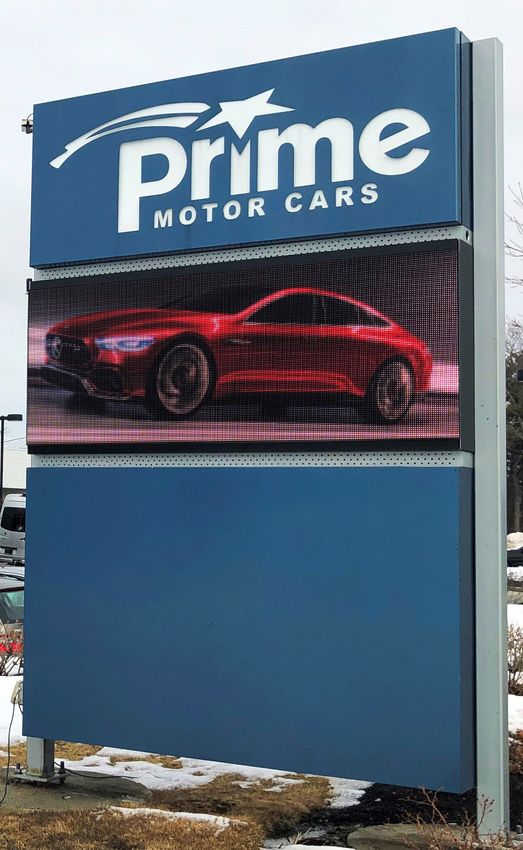
BladeM LED Display System
                                                                                                                                                Installation Manual

   Table of Contents

A. Introduction                                                                                                                          3
   1. Equipment description                                                                                                              3
   2. Safety/compliance information                                                                                                      8
   3. Environmental considerations                                                                                                       9
   4. Shipping/receiving, product storage                                                                                                9
   5. Warranty terms for all displays                                                                                                   10

B. Frames and Assembly                                                                                                                  13
   Frame assembly                                                                                                                       13
   Frame mounting                                                                                                                       14
   Ventilation                                                                                                                          15

C. Electrical Section                                                                                                                   16
   Power cable                                                                                                                          16
   Power injectors                                                                                                                      17

D. Controller                                                                                                                           18
   M1 Pro Controller details                                                                                                            18
   Mounting the M1 Pro Controller                                                                                                       19
   Extension cables                                                                                                                     19
   Connecting the all-in-one antenna                                                                                                    20
   Mounting the all in-one-antenna                                                                                                      21
   M1 Pro indicator codes                                                                                                               22
   Automapping procedure                                                                                                                23

E. Panels                                                                                                                               23
   Connecting panels                                                                                                                    24
   Cable connections                                                                                                                    25
   Wiring pattern                                                                                                                       26

F. Network Connections                                                                                                                  27
   Important network information (Ethernet or WiFi kit only)                                                                            28
   WiFi kit installation                                                                                                                29
   Connecting the WiFi kit                                                                                                              30

        Cirrus | 200 West Rd, Portsmouth, NH 03801 | 877 636 2331 | contact@cirrusled.com | cirrusled.com
        This document is confidential & proprietary to Cirrus Systems for distribution to direct customers and their installers only.
                                                                                                                                                                2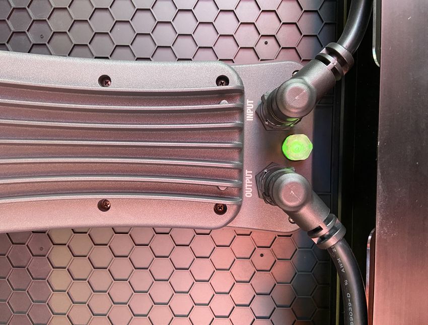
BladeM LED Display System
                                                                                                                                                  Installation Manual

    A. Introduction

1. Equipment description
BladeM LED Displays are modular signs consisting of these components:

  Frames

1’x2’ Cirrus frame                                                                                       1’x2’ Legacy frame

                                                                            Frame bolts, ¼”-20x0.5”

          Cirrus | 200 West Rd, Portsmouth, NH 03801 | 877 636 2331 | contact@cirrusled.com | cirrusled.com
          This document is confidential & proprietary to Cirrus Systems for distribution to direct customers and their installers only.
                                                                                                                                                                  3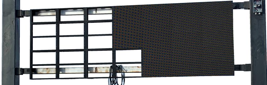
BladeM LED Display System
                                                                                                                                            Installation Manual

BladeM 9mm LED sign module

                                                                                                   Rear view

                                                                                   Panel cable

    Cirrus | 200 West Rd, Portsmouth, NH 03801 | 877 636 2331 | contact@cirrusled.com | cirrusled.com
    This document is confidential & proprietary to Cirrus Systems for distribution to direct customers and their installers only.
                                                                                                                                                            4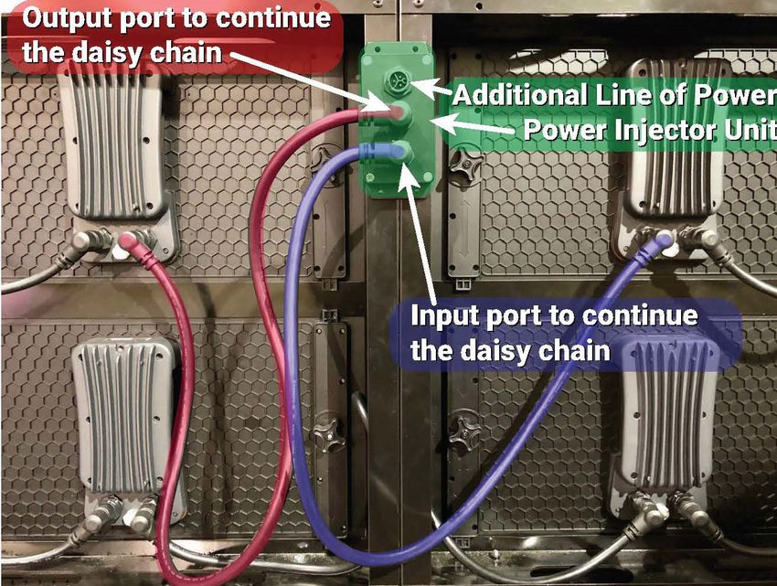
BladeM LED Display System
                                                                                                                                                       Installation Manual

  Controller box
To manage single and dual-sided signs.

M1 Pro Controller                                                                                       M1 Pro Controller mounting bracket

                     10’ Extension cable (x2)                                                                                            Power cable

         Cirrus | 200 West Rd, Portsmouth, NH 03801 | 877 636 2331 | contact@cirrusled.com | cirrusled.com
         This document is confidential & proprietary to Cirrus Systems for distribution to direct customers and their installers only.
                                                                                                                                                                       5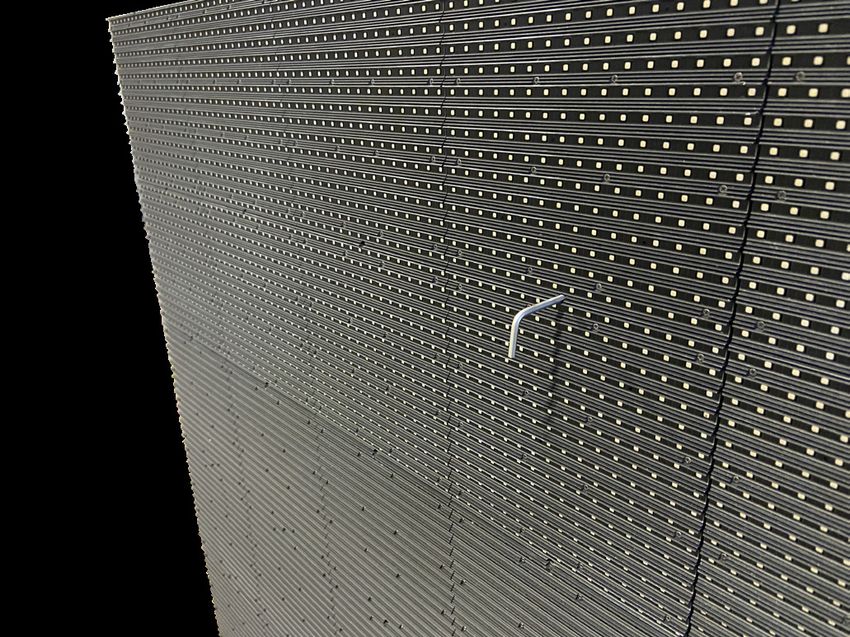
BladeM LED Display System
                                                                                                                                                        Installation Manual

  All-in-one antenna

All-in-one antenna

   Optional wireless access kit

                       TP-Link wireless kit                                                                                       10’ Ethernet cable (x2)

         Cirrus | 200 West Rd, Portsmouth, NH 03801 | 877 636 2331 | contact@cirrusled.com | cirrusled.com
         This document is confidential & proprietary to Cirrus Systems for distribution to direct customers and their installers only.
                                                                                                                                                                        6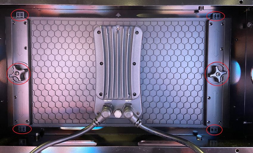
BladeM LED Display System
                                                                                                                                                 Installation Manual

  Power injector
(optional, may not be included)

Power injector                                                                                          Power cable

                                                                                        Panel cable

         Cirrus | 200 West Rd, Portsmouth, NH 03801 | 877 636 2331 | contact@cirrusled.com | cirrusled.com
         This document is confidential & proprietary to Cirrus Systems for distribution to direct customers and their installers only.
                                                                                                                                                                 7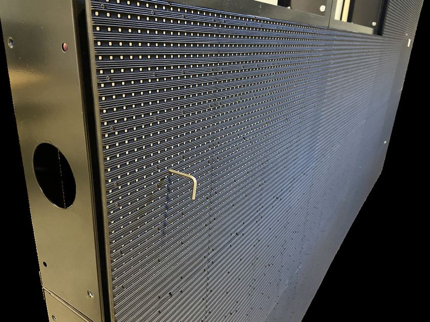
BladeM LED Display System
                                                                                                                                                         Installation Manual

2. Safety/compliance information

                            High voltage

                            Contact with high voltage from AC mains may cause death or serious injury. Always
                            disconnect AC power to unit prior to servicing.

                            Grounding

                            It is essential to earth-ground the sign before connecting controller. Connecting
                            signs that are not earth grounded may cause damage to the LED Display System
                            and in severe cases cause death or injury.

                            Other

                            Other safety messages appear throughout this manual where appropriate.

Cirrus LED components are UL Listed. File #E352796 and FCC Certified.

  FCC information
                                                                                                                                                                        BLADE M LED DISPLAY SYST
                                                                                                                                                                             INSTALLATION MANU
This equipment has been tested and found to comply with
the limits for a Class A digital device, pursuant to part 15
of the FCC Rules. These limits are designed to provide                                                    FCC Information
reasonable protection against harmful interference when the
equipment is operated in a commercial environment. This
equipment generates, uses, and can radiate radio frequency
energy and, if not installed and used in accordance with the
instruction manual, may cause harmful interference to radio
communications. Operation of this equipment in a residential
area is likely to cause harmful interference in which case the
user will be required to correct the interference at his own
expense.

Changes or modifications to this device that are not expressly                                            This equipment has been tested and found to comply with the limits for a Class A digital
                                                                                                          device, pursuant to part 15 of the FCC Rules. These limits are designed to provide reasonable
approved by Cirrus Systems, Inc. could void user’s authority to                                           protection against harmful interference when the equipment is operated in a commercial
                                                                                                          environment. This equipment generates, uses, and can radiate radio frequency energy and,
operate this device.                                                                                      if not installed and used in accordance with the instruction manual, may cause harmful
                                                                                                          interference to radio communications. Operation of this equipment in a residential area is
                                                                                                          likely to cause harmful interference in which case the user will be required to correct the
                                                                                                          interference at his own expense.
                                                                                                          Changes or modifications to this device that are not expressly approved by Cirrus Systems,
                                                                                                          Inc. could void user’s authority to operate this device.

         Cirrus | 200 West Rd, Portsmouth, NH 03801 | 877 636 2331 | contact@cirrusled.com | cirrusled.com
         This document is confidential & proprietary to Cirrus Systems for distribution to direct customers and their installers only.
                                                                                                                                                                                     8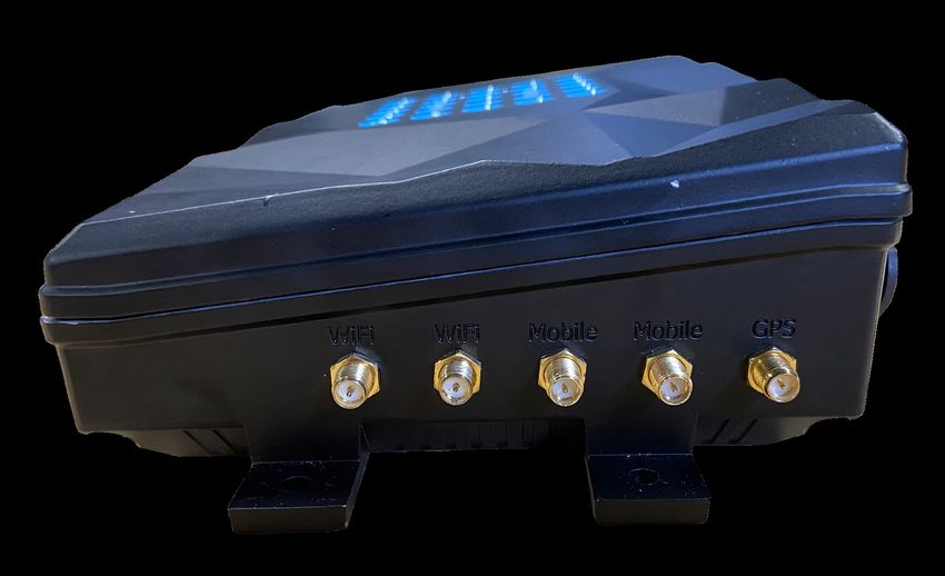
BladeM LED Display System
                                                                                                                                                  Installation Manual

3. Environmental considerations

The BladeM LED panels are fully encapsulated and water-proof. The M1 Pro Controller is housed in
a water-proofed aluminum enclosure.

The BladeM LED panels are rated for an ambient operating temperature range of -40~+70° Celsius (-40
~ +158° Fahrenheit) and are designed to withstand continuous direct sunlight. If the panels experience
an over-temperature condition, a signal will be sent to the controller to shut down the sign. Once the
sign has cooled, it will automatically re-start.

The M1 Pro Controller is rated for an ambient operating temperature range of -10~+60°C (14~ +140°F)
and should be protected from direct sunlight. Operation at colder temperatures is routinely and
regularly accomplished, though starting the screen from a powered off state at temperatures below
14°F may not be possible. A controller which is in a powered on state produces ambient heat which
can allow it to continuously run at temperatures as low as -30°F (-34°C).

All components and connections are sealed and water-tight for protection from the ingress of dust and
water, though no components should be subjected to immersion in water.

4. Shipping & Receiving, product storage

All deliveries shall be FOB Cirrus Systems (Seller), Portsmouth, NH. Methods and routes of
shipment, unless Seller specifies in writing otherwise, shall be accepted as chosen by Seller at
Seller’s sole discretion. Purchaser shall pay all costs of shipment. Delivery to the carrier shall
constitute delivery and passage of title to Purchaser, and risk of loss shall pass to Purchaser
concurrently with passage of title. Seller will use reasonable diligence to meet scheduled shipment
dates and times. Such dates and times are the best possible estimates, and not guarantees, of
when goods will be shipped. In no event shall Seller be liable for any losses or damages of any kind
due to delays in shipment, nor may Purchaser cancel its contract because of any such delay.

It is the responsibility of the Purchaser to check the Product for visible damage prior to accepting delivery
from the carrier. Any damage to the Product must be noted on the delivery slip with the carrier and
immediately reported to Cirrus. Photographic evidence of damages will be required. Cirrus may assist in
seeking remedy with the carrier for damaged goods but does not retain title and therefore is not legally
responsible for said damages.

Delivered product should be stored in a cool dry place, out of the way of foot/motorized traffic.

It is the installer’s responsibility to look over the product before installing to ensure there are no
missing parts and there is no visible damage to any parts of the display. If there is any damage,
Cirrus must be informed prior to install.

          Cirrus | 200 West Rd, Portsmouth, NH 03801 | 877 636 2331 | contact@cirrusled.com | cirrusled.com
          This document is confidential & proprietary to Cirrus Systems for distribution to direct customers and their installers only.
                                                                                                                                                                  9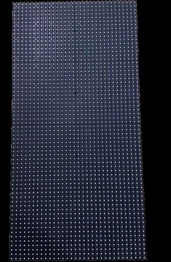
BladeM LED Display System
                                                                                                                                                  Installation Manual

5. Warranty terms for all displays

What this warranty covers
This warranty covers any defects, failures, or malfunctions of any Cirrus LED display system
hardware. All inspections of warrantied components will be conducted within 72 hours and results
will be presented immediately thereafter and applicable charges will be sustained or reimbursed at
that time.

9mm pixel warranty (per panel) - 1st year, 100% pixel guarantee, 2 pixels for years 2-3 and then 3
pixels for years 4-5.

6mm pixel warranty (per panel) - 1st year, 100% pixel guarantee, 4 pixels for years 2-3 and then 6
pixels for years 4-5.

Coverage period
This warranty lasts for five calendar years following the purchase of any Cirrus LED display system.
Warranty may not be exercised until the display has been installed, powered, connected to the
Internet and Cirrus has verified adequate setup. Displays that are stored for extended periods of
time and not installed within 90 days of shipment may not qualify for warranty coverage at the
discretion of Cirrus Systems Inc. Coverage terminates if an end user sells, transfers, opens or
tampers with any display system or its internal components.

What’s covered
Cirrus will replace any defective or malfunctioning part at no charge and pay for shipping. All
defective parts must be returned to Cirrus Systems for servicing upon failure. Replacement
components will be dispatched once a credit card has been secured to guarantee the return of the
defective part. Replaced parts are required to be returned within 45 days of shipment or a charge
for the cost of the replacement part will be applied to the held credit card.

What’s not covered
This warranty does not cover labor costs or any problem that is caused by abuse, misuse,
improper installation, or an act of God. Also, consequential and incidental damages are not
recoverable under this warranty. Some states do not allow the exclusion or limitation of incidental
or consequential damages, so the above limitation or exclusion may not apply to you. Cirrus will not
be responsible for any labor charges incurred during assembly, disassembly, or any other services
related to the part replacement.

Service eligibility
Any company or individual that purchases a display from Cirrus Systems or from an authorized
Cirrus distributor is eligible for this warranty and service. If issues are experienced with any display
system, contact Cirrus at (877) 636-2331 and follow the prompts for technical support.

          Cirrus | 200 West Rd, Portsmouth, NH 03801 | 877 636 2331 | contact@cirrusled.com | cirrusled.com
          This document is confidential & proprietary to Cirrus Systems for distribution to direct customers and their installers only.
                                                                                                                                                                 10
BladeM LED Display System
Installation Manual
Exclusions: The following issues are not covered under the limited warranties set
forth above. For these issues, Cirrus shall not be obligated to furnish warranty
support or maintenance services, nor shall Cirrus be liable hereunder for repairs,
replacement or additions:
01. D
amage or problems caused during transportation by Customer;
02. D
efects or damage that result from use of the Products or Software in other than their normal
and customary manner;
03. D
amage or problems caused by repairs, changes, modifications, maintenance, relocation or re-
installation by other than Cirrus designated technicians, or without Cirrus’s written permission;
04. P
roducts and Software subject to unauthorized modification, disassembly or repair (including
the addition to the Product of non-Cirrus authorized and supplied equipment) which adversely
affect Product or Software performance or interfere with Cirrus’s normal warranty inspection
and Product or Software testing for warranty verification;
05. P
roducts which, due to illegal or unauthorized alteration of Product software or firmware, do
not function in accordance with Cirrus’s published specifications;
06. D
amage or problems caused by not following Electro-Static Discharge (“ESD”) precautions
when handling Covered Products;
07. D
amage or problems caused by improper electrical grounding;
08. D
amage or problems caused by improper utility service;
09. D
amage or problems caused by use of non-Cirrus supplied equipment or parts;
10. D
amage or problems caused by misuse, abuse, neglect or accident;
11. D
amage or problems caused by an external electrical fault or any unusual shock;
12. D
amage or problems caused by an accident, fire or water;
13. D
amage or problems caused by natural disasters such as flood, fire, lightning, earthquake or
tornado.
14. D
amage or problems caused by failure to maintain the proper operating or storage
environment for the Covered Products to include but not limited to air conditioning, humidity
control, or corrosive atmosphere harmful to electronic equipment as provided in the Cirrus
Installation Manual;
15. D
amage or problems caused by strikes, riots, sabotage, or acts of war;
16. T
heft;
17. R
outine cleaning, or normal and customary wear and tear;
18. S
cratches or other cosmetic damage to Product surfaces that do not affect the operation of the
Product;
19. T
echnical support or maintenance of any kind for third-party application or custom software not
defined under Covered Products;
20. T
echnical support associated with programming of Application Program Interfaces (API) of
Covered Products except for support on the capabilities of the programming interface;
21. C
onsumables and supplies (i.e., expendable batteries, recording media, tapes, disks or other
consumables);
22. F
reight costs to the repair depot;
23. N
on-Cirrus manufactured equipment, which carries its original manufacturer’s warranty and
which will be provided to Customer upon request.
Cirrus | 200 West Rd, Portsmouth, NH 03801 | 877 636 2331 | contact@cirrusled.com | cirrusled.com
This document is confidential & proprietary to Cirrus Systems for distribution to direct customers and their installers only.
11BladeM LED Display System
Installation Manual
Warranty activation
The 5 year product warranty will go into effect upon the date of shipment and transfer of title. Warranty
may not be exercised until the display has been installed, powered, connected to the Internet and Cirrus
has been called to verify the installation. Displays which are stored for extended periods of time and not
installed within 90 days of shipment may not qualify for warranty coverage at the discretion of Cirrus
Systems Inc.
TP-Link Wifi kit warranty
Cirrus will cover the first year of warranty of the TP-Link WiFi kit and its power supply. After the first year of
use, client must work through the warranty with TP-Link directly.
Disclaimer
Except as expressly set forth in this Agreement, the Products and Software, including the Hardware, and
all related Services shall be provided “as is” without warranty of any kind, and Cirrus hereby disclaims,
and Customer hereby waives, any and all warranties whether express, implied or statutory, including all
implied warranties of merchantability, fitness for a particular purpose and non-infringement. Further, Cirrus
does not warrant, guarantee, or make any representations that any Software provided will be free from all
bugs or that its use will be uninterrupted or error-free. Customer understands and agrees that Cirrus is not
responsible for and will have no liability for equipment hardware, software, or other items or any services
provided by or manufactured by any persons other than Cirrus or its authorized agents. The foregoing
constitutes Customer’s sole rights and remedies under this agreement with respect to defects in the
products, software or services.
Limitation on liability
Buyer understands and agrees that except for instances involving Cirrus’s indemnification obligations set
forth in the governing Sales Agreement, Cirrus’s aggregate liability for any damages suffered by Buyer or
any other party, whether in contract, in tort, under any warranty theory, or otherwise, shall be limited to the
amount paid to Cirrus by Buyer under this Contract for the defective System component(s) giving rise to
the indemnified losses or damages covered by this Agreement.
Cirrus | 200 West Rd, Portsmouth, NH 03801 | 877 636 2331 | contact@cirrusled.com | cirrusled.com
This document is confidential & proprietary to Cirrus Systems for distribution to direct customers and their installers only.
12BladeM LED Display System
Installation Manual
B. Frames and assembly
Frame assembly
1’ tall x 2’ wide frames
are assembled using the
included ¼” hex bolts. It is
important to ensure that
all frames are attached
with the arrows facing
front and up.
Four bolts should be
used on each side of
the frame and should
be tightly fastened to
ensure there are no gaps
between the panels. Two
bolts will go in from one
direction and two will
go in from the opposite
direction,
on each side.
Cirrus | 200 West Rd, Portsmouth, NH 03801 | 877 636 2331 | contact@cirrusled.com | cirrusled.com
This document is confidential & proprietary to Cirrus Systems for distribution to direct customers and their installers only.
13BladeM LED Display System
Installation Manual
Frame mounting
One row of support mounting brackets(not supplied) must be attached for every four rows of frames. Do
not exceed four rows of frames without attaching an additional mounting bracket.
Supports
Required
Here
Mounting brackets should be attached for the entire horizontal length of the frames to prevent bowing or
lateral stress.
Cirrus | 200 West Rd, Portsmouth, NH 03801 | 877 636 2331 | contact@cirrusled.com | cirrusled.com
This document is confidential & proprietary to Cirrus Systems for distribution to direct customers and their installers only.
14BladeM LED Display System
Installation Manual
Ventilation
BladeM LED panels are passively cooled, so adequate ventilation is required to keep the
display within normal operating temperatures (-40 ~+70 C or -40 ~+158 F). Allowing
natural convection by venting the top and bottom of the display is ideal. Screen, mesh,
or perforated material can be used to enclose the framing system.
Some examples of perforated materials
Note: Proper ventilation is a requirement for the warranty. If top and bottom venting is not an option (as in the case of some
monument signs), as much side venting as possible will be required. Space behind the display in the cabinet may also
be acceptable.
Cirrus | 200 West Rd, Portsmouth, NH 03801 | 877 636 2331 | contact@cirrusled.com | cirrusled.com
This document is confidential & proprietary to Cirrus Systems for distribution to direct customers and their installers only.
15BladeM LED Display System
Installation Manual
C. Electrical section
The BladeM system is designed to be powered by up to 240-volt service, without any additional
configuration or equipment. The exact electrical requirements will be determined by the number of
panels. Cirrus is unable to provide, consult, or advise on the electrical setup on the
display. All electrical work must be done by a licensed electrician in accordance
with local laws and regulations.
With the introduction of the M1 Pro Controller, there is now a built-in power detection system. If
power issues are detected (such as insufficient power for the number of panels), the panels will be
shut off automatically as a safety measure. A rapidly flashing red light on the Controller will indicate a
power issue. Cirrus Tech Support should be contacted before restoring power to the panels.
Note: All electrical breakers should be no more than 20 amps
Note: Breakers can not be shared with any other equipment (other LED drivers, cabinet lighting, etc),
and should not have any sort of timer on them.
9 mm 6 mm
120 Volt 18 panels max per circuit 16 panels max per circuit
240 Volt 36 panels max per circuit 32 panels max per circuit
For signs requiring more than one circuit of power, a power injector(s) will be used to provide additional
power. Refer to the power injector section for more details.
Power cable
Green — Ground
Black — Hot
White — Neutral (120-volt service)
or hot (240-volt service)
Note: Displays must be properly grounded (at the breaker or at the display). Electrical damage is not covered under our
warranty (refer to the warranty section for details).
Cirrus | 200 West Rd, Portsmouth, NH 03801 | 877 636 2331 | contact@cirrusled.com | cirrusled.com
This document is confidential & proprietary to Cirrus Systems for distribution to direct customers and their installers only.
16BladeM LED Display System
Installation Manual
Power injectors
Power injectors are used in cases where a sign requires more than a single line of power. Cirrus will
advise on where to place power injectors as part of the pre-install process.
Power Output Input
The power injector has three ports - one for the power cable, a cable input, and a cable output.
Cirrus | 200 West Rd, Portsmouth, NH 03801 | 877 636 2331 | contact@cirrusled.com | cirrusled.com
This document is confidential & proprietary to Cirrus Systems for distribution to direct customers and their installers only.
17BladeM LED Display System
Installation Manual
D. Controller
M1 Pro Controller details
Power Port A Port B Ethernet
WiFi Cell GPS
Button Indicator light
Cirrus | 200 West Rd, Portsmouth, NH 03801 | 877 636 2331 | contact@cirrusled.com | cirrusled.com
This document is confidential & proprietary to Cirrus Systems for distribution to direct customers and their installers only.
18BladeM LED Display System
Installation Manual
Mounting the M1 Pro Controller
The M1 Pro Controller is recommended
to be mounted inside the sign, to prevent
unwanted access. It can be placed outside,
but should not be mounted in direct
sunlight.
The M1 Pro Controller should be mounted
with the side with no ports facing up, so no
water can pool in them. Pooling water may
eventually cause damage to the interior
components.
The M1 Pro Controller can be mounted
using the optional M1 Pro Controller
mounting bracket (see below). The
mounting bracket should be attached using
self-tapping screws to a secure location.
Extension cables
The included extension cables can be used
to enable mounting the controller further
away from the first panel in the chain.
When using an extension, a 2’ panel cable
must be used to connect to a panel.
Note: Do not use two extension cables connected
together, it may result
in data loss and display issues.
Cirrus | 200 West Rd, Portsmouth, NH 03801 | 877 636 2331 | contact@cirrusled.com | cirrusled.com
This document is confidential & proprietary to Cirrus Systems for distribution to direct customers and their installers only.
19BladeM LED Display System
Installation Manual
Connecting the all-in-one antenna
The all-in-one antenna has 5 leads, 2 for wifi (unlabeled), 2 for cellular (purple, labeled LTE), and a
GPS lead (blue).
The two wifi leads should be secured to the WiFi posts, the LTE leads should be secured to the
mobile connections, and the GPS lead should be secured to the GPS connector.
WiFi LTE GPS
Cirrus | 200 West Rd, Portsmouth, NH 03801 | 877 636 2331 | contact@cirrusled.com | cirrusled.com
This document is confidential & proprietary to Cirrus Systems for distribution to direct customers and their installers only.
20BladeM LED Display System
Installation Manual
Mounting the all-in-one antenna
The all-in-one is designed to be fed mounted directly on the top or side of the sign. The cables can
be fed through one of the openings on the frame, and then the locking nut secured down to hold it
in place. The rear of the antenna also has 3M peel and stick tape which can be used to adhere to
the in place of the locking nut.
Cirrus | 200 West Rd, Portsmouth, NH 03801 | 877 636 2331 | contact@cirrusled.com | cirrusled.com
This document is confidential & proprietary to Cirrus Systems for distribution to direct customers and their installers only.
21BladeM LED Display System
Installation Manual
M1 Pro indicator codes
Indicator State Meaning Action
Steady green light
Power on n/a
Green light
flashes every 5 seconds Power on, system
n/a
monitoring active
Steady red light
To restore power- hold button
Power to modules
down for 2 seconds. Release when
is disabled
light turns green
3 green flashes, followed
by a pause, for 10 seconds Network connection Initiate network test -
is active Press button once quickly
3 red flashes, followed
by a pause, for 10 seconds Network connection Initiate network test -
is NOT active Press button once quickly
Steady blue light To initiate Automap - press and
Automapping complete, test patterns
hold button for 5 seconds.
will show for 2 minutes or until
To exit mode early - press button
canceled
once quickly
Flashing red
for 10 seconds
Automapping failed n/a
Flashing red every
0.5 seconds Power issue detected. Panels shut
Contact Cirrus Support
down
Flashing green every
0.5 seconds
Power issue overridden Contact Cirrus Support
Cirrus | 200 West Rd, Portsmouth, NH 03801 | 877 636 2331 | contact@cirrusled.com | cirrusled.com
This document is confidential & proprietary to Cirrus Systems for distribution to direct customers and their installers only.
22BladeM LED Display System
Installation Manual
Automapping
With our patented automapping technology, new signs can be installed without even making a phone call. After installing and
connecting the M1 Pro Controller and all the panels. Following the instructions below will address all the panels and put the
controller into a diagnostic mode, which will check the network connection before returning to normal function.
Automapping
Step 1 Hold the button for Green indicator
5 seconds and release when the
light turns blue.
Step 2 There is a pause while the
controller attempts to send
mapping data to the panels.
Step 3 Once the automapping completes,
a system check is initiated. The
sign should show a panel map for
15 seconds, then a network status
for 15 seconds. These will continue Red indicator
alternating for 2 minutes or until
the Button is pressed once quickly.
If the auto-mapping process doesn’t complete
correctly, please reach out to Cirrus Support at
877-636-2331 option 2.
Blue indicator
Cirrus | 200 West Rd, Portsmouth, NH 03801 | 877 636 2331 | contact@cirrusled.com | cirrusled.com
This document is confidential & proprietary to Cirrus Systems for distribution to direct customers and their installers only.
23BladeM LED Display System
Installation Manual
E. Panels
Cirrus BladeM panels are secured onto the framing system using 2 locking mechanisms. The panels
should fit only one way, with the input and output port on the bottom of the panel. The locking arms are
controlled by the knobs on either side of the panel.
Front access
The locking mechanism can also be accessed from the front of the display for service purposes using a 2.5 mm
Allen wrench. There is a small hole opposite the knobs on the rear of the sign.
Cirrus | 200 West Rd, Portsmouth, NH 03801 | 877 636 2331 | contact@cirrusled.com | cirrusled.com
This document is confidential & proprietary to Cirrus Systems for distribution to direct customers and their installers only.
24BladeM LED Display System
Installation Manual
Connecting panels
Each panel will have an input cable and an output cable (except the last panel in the chain). Each port
should be labeled with the input on the right and the output on the left (when facing the back of the
panel).
Cirrus | 200 West Rd, Portsmouth, NH 03801 | 877 636 2331 | contact@cirrusled.com | cirrusled.com
This document is confidential & proprietary to Cirrus Systems for distribution to direct customers and their installers only.
25BladeM LED Display System
Installation Manual
Cable connections
1. Align connector 2. G
rip heatsink with fingers to pull while pushing
connector with thumbs. This push/pull method will
avoid damaging the panel.
3. Use thumb to twist lock into place 4. Pull gently on cable to ensure lock is in place
Using excess force when seating cables can lead to panel damage which will be
present on display screen.
Cirrus | 200 West Rd, Portsmouth, NH 03801 | 877 636 2331 | contact@cirrusled.com | cirrusled.com
This document is confidential & proprietary to Cirrus Systems for distribution to direct customers and their installers only.
26BladeM LED Display System
Installation Manual
Wiring pattern
It is recommended to use the following daisy chain pattern when connecting
modules together.
Port A
When facing the back of the 3x6
3x6wiring example-–Port
wiring example portAA
sign start at bottom left corner
then go up to the top left, then
over one column, then down to
the bottom, and so on.
Data
port AA
Port
Port B
When facing the back of the
3x6 wiring
3x6 wiring example
example- –Port
portBB
sign start at bottom right corner
then go up to the top right, then
over one column, then down to
the bottom, and so on.
Data
Data
port
PortBB
Cirrus | 200 West Rd, Portsmouth, NH 03801 | 877 636 2331 | contact@cirrusled.com | cirrusled.com
This document is confidential & proprietary to Cirrus Systems for distribution to direct customers and their installers only.
27BladeM LED Display System
Installation Manual
F. Network connections
An active network connection is required to use your Cirrus BladeM display. The display can be
connected one of three ways
Cellular broadband
Cellular broadband is optional on all Cirrus BladeM displays. Cellular coverage can vary from location to
location, so may not always be the best solution. Your sales rep can give you more information.
Both the WiFi kit and the cellular broadband will require the installation of the all-in-one antenna.
Ethernet Note: The maximum run
on Ethernet is 300 ft, any
distance greater than that can
A direct Ethernet connection can be be run with fiber optic cable,
plugged into the Ethernet port (labeled LAN) but will need to converted
back to Ethernet before
of the M1 Pro Controller pictured below.
connecting to the controller.
Note: The maximum
distance between the wifi kit
WiFi kit (Optional) and the sign is roughly 300’
and maybe less depending
on the line of sight. A second
wifi kit can be added to make
The included WiFi kit (pictured below)
a paired set which more
is preconfigured and is intended to be than doubles that distance.
plugged into the location’s network to Contact your Cirrus Support
broadcast a “CirrusLED” WiFi network, which for details and cost.
our controllers connect to automatically.
Installation instructions are on page 30.
Cirrus | 200 West Rd, Portsmouth, NH 03801 | 877 636 2331 | contact@cirrusled.com | cirrusled.com
This document is confidential & proprietary to Cirrus Systems for distribution to direct customers and their installers only.
28BladeM LED Display System
Installation Manual
Important network information (Ethernet or WiFi kit only)
Both the Ethernet and WiFi kit have been preset to work with unrestricted access to the internet, through
the customer’s network. The default IP scheme is via DHCP.
In the case of a restricted network (firewalls, or static IP addresses), additional configuration can be
performed. This is most easily performed before installation, so reach out to Tech Support.
Cirrus | 200 West Rd, Portsmouth, NH 03801 | 877 636 2331 | contact@cirrusled.com | cirrusled.com
This document is confidential & proprietary to Cirrus Systems for distribution to direct customers and their installers only.
29BladeM LED Display System
Installation Manual
WiFi kit installation (Optional)
Inside the WiFi kit box are the following components:
Wireless access point Power over Ethernet PoE power cable
or WAP or PoE
Not pictured but required for installation are (2) Ethernet cables. We include (2) 10’ Ethernet cables as part
of the controller kit, but longer ones may be substituted if necessary. Cat5 or Cat6 are both acceptable.
The maximum run for standard Ethernet is 300’. Longer distances may be covered with fiber optic cable
but must be converted back to standard Ethernet to connect to the controller.
Cirrus | 200 West Rd, Portsmouth, NH 03801 | 877 636 2331 | contact@cirrusled.com | cirrusled.com
This document is confidential & proprietary to Cirrus Systems for distribution to direct customers and their installers only.
30BladeM LED Display System
Installation Manual
Connecting the optional WiFi kit
The WAP is designed to be hung outside, with the flat front (has the logo printed on it) facing towards the
sign. Line of sight is important to prevent signal loss, so putting it inside, pointing in a different direction, or
through a screen of trees can all prevent good communication.
The PoE should be connected to a 120v outlet no more than 30’ from the WAP. An Ethernet cable
connects the PoE to the WAP, with one end plugged into the Ethernet port on the rear of the WAP, and
the other on the PoE port of the PoE unit (see below).
Connects to Connects to
rear of WAP customer network
Ethernet connection from PoE
The other port on the PoE labeled LAN should be connected via Ethernet directly into the customer’s
existing network switch, router, or gateway. This cable length can be up to 300’.
Note: The WAP will NOT work if it is connected to a computer or laptop. If you have questions, please contact Cirrus
Support.
Note: Pushing the reset button on the WAP erases all pre-configured settings, so it should never be done unless
directed to by a member of Cirrus Tech Support.
Cirrus | 200 West Rd, Portsmouth, NH 03801 | 877 636 2331 | contact@cirrusled.com | cirrusled.com
This document is confidential & proprietary to Cirrus Systems for distribution to direct customers and their installers only.
31You can also read