Investigation of Nondestructive Testing Methods for Friction Stir Welding - MDPI
←
→
Page content transcription
If your browser does not render page correctly, please read the page content below
metals
Review
Investigation of Nondestructive Testing Methods for
Friction Stir Welding
Hossein Taheri 1, * , Margaret Kilpatrick 2 , Matthew Norvalls 3 , Warren J. Harper 3 ,
Lucas W. Koester 4 , Timothy Bigelow 3,4 and Leonard J. Bond 3,5
 1   Department of Manufacturing Engineering, Georgia Southern University, Statesboro, GA 30460, USA
 2   Department of Mechanical Engineering, Georgia Southern University, Statesboro, GA 30460, USA;
     mk03650@georgiasouthern.edu
 3   Department of Mechanical Engineering, Iowa State University, Ames, IA 50011, USA;
     matthew.norvalls@gmail.com (M.N.); wjharper5@gmail.com (W.J.H.); bigelow@iastate.edu (T.B.);
     bondlj@iastate.edu (L.J.B.)
 4   Center for Nondestructive Evaluation (CNDE), Iowa State University, Ames, IA 50011, USA;
     lkoester@iastate.edu
 5   Department of Aerospace Engineering, Iowa State University, Ames, IA 50011, USA
 *   Correspondence: htaheri@georgiasouthern.edu; Tel.: +1-912-478-7463

 Received: 15 April 2019; Accepted: 23 May 2019; Published: 29 May 2019

 Abstract: Friction stir welding is a method of materials processing that enables the joining of similar
 and dissimilar materials. The process, as originally designed by The Welding Institute (TWI), provides
 a unique approach to manufacturing—where materials can be joined in many designs and still retain
 mechanical properties that are similar to, or greater than, other forms of welding. This process is
 not free of defects that can alter, limit, and occasionally render the resulting weld unusable. Most
 common amongst these defects are kissing bonds, wormholes and cracks that are often hidden from
 visual inspection. To identify these defects, various nondestructive testing methods are being used.
 This paper presents background to the process of friction stir welding and identifies major process
 parameters that affect the weld properties, the origin, and types of defects that can occur, and potential
 nondestructive methods for ex-situ detection and in-situ identification of these potential defects,
 which can then allow for corrective action to be taken.

 Keywords: friction stir welding (FSW); defects; mechanical properties; nondestructive testing &
 evaluation (NDT&E); in-line monitoring

1. Introduction
     Friction stir welding (FSW) is a joining process that was first demonstrated by The Welding
Institute (TWI) of Great Britain in 1991 [1]. Since that time, FSW use has soared, and by the end of
2007, TWI had issued 200 licenses for the process. Its applications continue to grow. In addition,
approximately nineteen hundred patent applications have also been filed relating to aspects of FSW [2,3].
The popularity of the process can be related to the multiple advantages that FSW offers, when compared
with other jointing modalities, including the ability to join vastly different metals, when performed
correctly, achieve minimal defect creation, maintain much higher material strength along the bonds
than typical for other joints, and provide smooth surfaces after joining.
     In performing the FSW process it typically involves two metals clamped on a rigid surface that
serves as an anvil together and a rotating shoulder, a mechanical “stirring” device that resembles
a drill bit. The anvil serves to react the downward pressure, i.e., the plunge force, during the FSW
process. By forcing the rotating shoulder into the materials along the weld interface, a frictional force

Metals 2019, 9, 624; doi:10.3390/met9060624                                     www.mdpi.com/journal/metals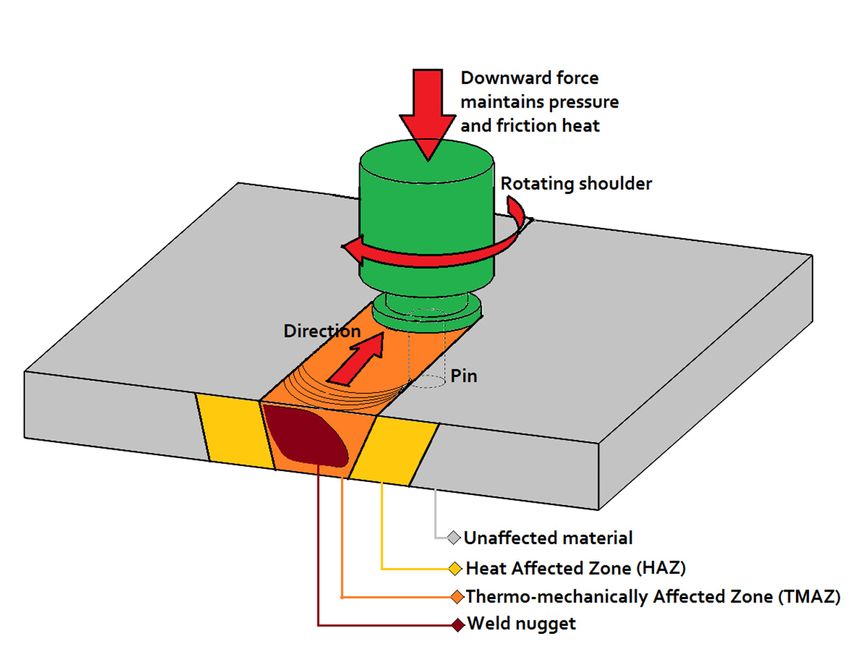
Metals 2019, 9, x; doi: FOR PEER REVIEW 2 of 22
Metals 2019, 9, 624 2 of 22
is generated due to the high speeds and maintained downward pressure of the rotating shoulder
against the metal plates. The resulting frictional heating creates a softened zone which is mechanically
is generated due to the high speeds and maintained downward pressure of the rotating shoulder
plasticized at the location of joining (Figure 1). The welding tool is simultaneously rotated and moved
against the metal plates. The resulting frictional heating creates a softened zone which is mechanically
along the desired weld line, blending the materials along the path. The resulting weld is typically
plasticized at the location of joining (Figure 1). The welding tool is simultaneously rotated and
stronger than that given by traditional fusion welding methods because it is formed at a lower
moved along the desired weld line, blending the materials along the path. The resulting weld is
temperature, which minimizes a heat-affected zone and this also reduces distortion and resulting
typically stronger than that given by traditional fusion welding methods because it is formed at a
residual stress. In addition, FSW is an environmentally friendly process, as it does not use shielding
lower temperature, which minimizes a heat-affected zone and this also reduces distortion and resulting
gas or filler material and it involves minimal energy input.
residual stress. In addition, FSW is an environmentally friendly process, as it does not use shielding
gas or filler material and it involves minimal energy input.
FrictionStir
Figure1.1.Friction
Figure StirWelding
Welding(FSW)
(FSW)tool
tooland
andsystem
systemsetup.
setup.
Since FSW
Since FSW isis typically
typically implemented
implemented in in an
an automated
automated process,
process, when when using
using correctly
correctly designed
designed
toolsand
tools andparameters,
parameters,defects
defectsshould
should notnot occur.
occur. However,
However, if the
if the process
process is incorrectly
is incorrectly controlled,
controlled, the
the resulting quality of the weld can be degraded. For any material
resulting quality of the weld can be degraded. For any material joining technique—No processjoining technique—No processisis
perfect,and
perfect, anddefects
defectscan canpotentially
potentiallyoccur.
occur.For For FSW
FSW wormholes,
wormholes, kissing
kissing bonds,
bonds, andand defects
defects causedcaused
by
by lack
lack of penetration
of penetration are typical
are the the typical
defectsdefects of current
of current concernconcern in industry
in industry [4,5]. [4,5]. With
With the usetheofuse
FSW of
FSW soaring, there is a need for nondestructive evaluation (NDE) processes
soaring, there is a need for nondestructive evaluation (NDE) processes that are superior to those that are superior to those
currentlyavailable
currently availablein inthe
themarket
market[6] [6] to
to provide
provide adequate
adequate quality
qualitycontrol
control[7], [7], particularly
particularlyfor forsafety
safety
critical applications.
critical applications.
Thenondestructive
The nondestructivetesting
testing(NDT)
(NDT) demands
demands by by industry
industry when whenFSWFSW is usedis used are fast
are that thatandfastcost-
and
cost-efficient
efficient methods
methods are provided
are provided to assess
to assess thethe weld
weld quality.
quality. Although
Although weldsare
welds aregenerally
generallyofofhighhigh
quality, some heterogeneity may arise due to the improper stirring of
quality, some heterogeneity may arise due to the improper stirring of the parent material, lack of the parent material, lack of
penetration of the tool pin, poor choice of tool pin design or improper choice
penetration of the tool pin, poor choice of tool pin design or improper choice of the process parameter of the process parameter
window. When
window. Whendefects
defectsdo dooccur,
occur,they
theyare areveryverydifferent
different in in form
form fromfrom those
those typically
typically found
found in in aa
conventional fusion welding
conventional fusion welding process. process.
AAfurther
furtherconstraint,
constraint,in interms
termsof ofinspection
inspectionneeds,needs,isisthat
thatthe
theFSW FSWmethod
methodisistypically
typicallyaahigh-end
high-end
fabrication method. Destructive evaluation of such welds in most
fabrication method. Destructive evaluation of such welds in most cases is not recommended for cases is not recommended
for evaluating
evaluating quality
quality sinceare
since they they are in
costly, costly,
termsin of terms of lost
lost items, anditems, and time to
time consuming consuming
conduct [8]. to
conductused
When [8]. When used destructive
destructive examination examination
techniques techniques
generally generally
involve involve bending
bending tests and
tests and
metallography/macrographs. In these techniques, the welded samples
metallography/macrographs. In these techniques, the welded samples are removed from the original are removed from the original
welding surface,
welding surface,but
butsuch
such samples
samplesonly onlyprovide
providedata data forfor the
the region
region where
where measurements,
measurements, such such asas
micrographs, are
micrographs, are taken.
taken. In Ingeneral,
general,evaluation
evaluationofofweld weld quality
qualityis most
is mostcommonly
commonly performed
performedpost-weld
post-
weld using conventional non-destructive testing methods, such as X-rays, ultrasonic testing,current
using conventional non-destructive testing methods, such as X-rays, ultrasonic testing, eddy eddy
and dyeand
current penetrant, althoughalthough
dye penetrant, the latertheare later
limitedaretolimited
detecting surface defects.
to detecting surfaceThe specific
defects. Thetype, size,
specific
Metals 2019, 9, 624                                                                                   3 of 22

shape and orientation of a defect all affect the detectability and characterization of the specific anomaly,
and this depends on the specific nondestructive method used [7,9].
     Several articles have reviewed different aspects of FSW, such as the joining of dissimilar
materials [10–12], FSW for joining particular alloys such as Aluminum and Magnesium or
processes [13–15], design and details of FSW tools [16,17] and numerical analysis of the FSW
process [18–20]. However, despite the importance of quality control of joints produced using FSW,
there are very few articles which discuss and describe the variety of defects which can occur in FSW
and the non-destructive testing (NDT) techniques that have been used or evaluated for inspection
of FSW [4,6]. This paper introduces the different types of defects in FSW, reviews the potential NDT
techniques for use in inspection of FSW and surveys the various real-time monitoring methods for use
in in-line inspection of the FSW process.

2. Applications of Friction Stir Welding
      FSW is ideal for applications where higher strength properties are required along the welded seam.
Examples of applications include those in the aircraft, marine, nuclear and the aero-space industries
where extreme environments require welds to reliably have specific properties. Additionally, FSW
welding typically creates stronger metallurgical bonds, it is also commonly a faster welding process,
and can enable fabrication of designs that reduce the overall complexity of many components. In most
cases, there is also a reduction in weight as no additional material was introduced. In the case of
aircraft manufacturing, FSW is especially beneficial as the use of rivets and raised weld beads that
can adversely impact the aerodynamics of the craft, can be avoided. This is especially important for
supersonic craft, as the drag increases exponentially with surface roughness.
      To take advantage of the benefits of using FSW, Eclipse Aerospace was one the first companies to
utilize the process and implemented it on their 500 and 550 series business jets. A total of 128 m of
friction stir welds was used on the jets and this replaced 60% of the rivets, resulting in a substantial
reduction in materials used and hence overall weight. Additionally, the use of FSW saved time, as
the welding process can be performed at a rate 10× faster than riveting, decreasing the time to build
one airframe substantially compared to an original 5 h. As a result of the adoption of the use of this
advanced welding process, the Eclipse 500 and 550 business jets were granted approval for double the
service life, as compared with the earlier versions, with an increase to 20,000 pressurization cycles.
This was due to the increased strength of the airframe, which was 3× stronger than those fabricated
using conventional riveting [20]. Since Eclipse started using FSW, other companies including Spirit
Aerosystems, Boeing, and Embraer have all begun production of components fabricated using FSW [21].
In addition to the aerospace industries, the possibility of improved fabrication of lightweight materials
makes FSW a good candidate for applications in the automotive and rail transportation fields [22].
      The aforementioned is just one of the multitudes of uses for FSW in today’s industries. The ability
to weld dissimilar metals and composites [7] with relative ease has now driven the process to be
adopted across various industries. The fact that this technique is superior in many ways compared to
traditional processes is why it has been so popular and rapidly adopted in a relatively short time. FSW is
a one of a kind material joining technique, which provided a new technology with significant potential
for improved joining of materials. The following sections describe the most common applications of the
FSW. However, it should be noted that there are a variety of other applications, which are developed
for FSW such as friction stir spot welding, multi-pass FSW, tandem stir welding and bobbin welding.
In this paper, the types of defects, mechanism of generation, and methods of NDT used for defect
detection is discussed. For more advanced application of FSW, such as mentioned above, the NDT
techniques might need to be adjusted accordingly.

2.1. Welding of Conventional Metals
     FSW is a solid-state process that can provide improvements over conventional welding in terms of
both quality and performance for a wide range of materials, specifically those which are difficult-to-weld,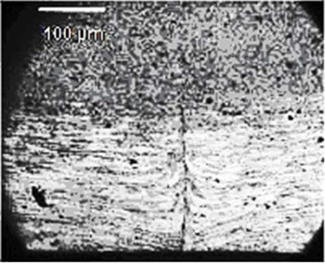
Metals 2019, 9, 624 4 of 22
Metals 2019, 9, x; doi: FOR PEER REVIEW 4 of 22
the as
such FSW material[23,24],
aluminum compareandfavorably
for cases with the properties
involving of themechanical
steel [25] where parent metal. Furthermore,
properties FSW
of the FSW
providescompare
material a lower-cost and more
favorably withenvironmentally
the properties offriendly process
the parent with
metal. less energy consumption
Furthermore, FSW providesand a
a more repeatable performance when compared with conventional joining [26].
lower-cost and more environmentally friendly process with less energy consumption and a more
repeatable performance when compared with conventional joining [26].
2.2. Welding of Dissimilar Materials
2.2. Welding of Dissimilar Materials
One of the main advantages of FSW is its ability to join dissimilar metals and alloys where the
One of themight
combination main advantages of FSW isinitsterms
not be compatible abilityofto chemical
join dissimilar metals and alloys
and mechanical wherewhen
properties the
combination
consideringmight not be compatible
conventional in terms of chemical
welding techniques. and mechanical
This is possible becauseproperties
FSW doeswhen considering
not involve bulk
conventional
melting of thewelding techniques.
materials Thisjoined
that are is possible because
[27,28]. FSWdissimilar
Joining does not involve bulk many
alloys has melting of the
different
materials that including
applications are joinedin[27,28]. Joining dissimilar
the automotive, aerospace alloys
and has many different
shipbuilding applications
industries including
where FSW can be
ina the automotive,
solution to cases aerospace
where thereandareshipbuilding
no alternativeindustries
conventionalwhere FSW can
welding be aavailable
method solution [10,29,30].
to cases
where there are
An example of no alternative conventional
a configuration welding method
for joining dissimilar materialsavailable [10,29,30].
with a butt An example
joint using a frictionofstir
a
configuration for joining
welding process, dissimilar
representing materials with
the importance a butt
of tool joint
offset onusing
FSW ofa friction stirmaterials
dissimilar welding process,
is shown
representing
in Figure 2. the importance of tool offset on FSW of dissimilar materials is shown in Figure 2.
(a) (b)
Figure Schematic
Figure2. 2. Schematicshowing
showingconfiguration
configurationfor joining dissimilar
for joining materials
dissimilar using a friction
materials using astir welding
friction stir
process.
welding(a) No tool(a)
process. offset, (b) Existence
No tool offset, (b) of tool offset.
Existence of tool offset.
2.3.
2.3.Friction
FrictionStir
StirAdditive
AdditiveManufacturing
Manufacturing
Friction
Frictionstir
stirwelding
weldingasasaasolid-state
solid-statejoining
joiningprocess
processcan
canbebeused
usedfor forfabrication
fabricationofofmultilayer
multilayer
metal
metal parts. This process works by joining metals layer-by-layer until the desiredshape
parts. This process works by joining metals layer-by-layer until the desired shapeandandthickness
thickness
ofofthe part is achieved [31,32]. The advantage of this method is that each previously
the part is achieved [31,32]. The advantage of this method is that each previously added layer added layer
acts
acts as a support for the next pass so that the structure is self-supported during the manufacturing
as a support for the next pass so that the structure is self-supported during the manufacturing process
process
[32,33].[32,33]. Investigations
Investigations show show that mechanical
that mechanical properties
properties of multilayer
of multilayer FSWFSW formed
formed materials
materials are
are comparable to those of the corresponding base metal. In addition, there are potentially
comparable to those of the corresponding base metal. In addition, there are potentially improved improved
mechanical
mechanicalproperties
propertiesininthetheweld
weldzone’
zone’when
whencompared
comparedtotothose
thosefor
forthe
thebase
basemetal
metal[32].
[32].
3. Standard Requirement for FSW
3. Standard Requirement for FSW
The application and implementation of FSW in any particular field varies depending on the
The application and implementation of FSW in any particular field varies depending on the
specific requirements of each industry, however; there are general standards and specifications for
specific requirements of each industry, however; there are general standards and specifications for
the process. As an example some of these standards and specifications for friction stir welding of
the process. As an example some of these standards and specifications for friction stir welding of
Aluminum are listed in Table 1. These specifications cover the general requirements for the FSW of
Aluminum are listed in Table 1. These specifications cover the general requirements for the FSW of
aluminum alloys and they include the requirements for weldment design, qualification of personnel
aluminum alloys and they include the requirements for weldment design, qualification of personnel
and procedures, fabrication, and inspection.
and procedures, fabrication, and inspection.
Table 1. Standards and Specification for Friction Stir Welding (FSW) of Aluminum Alloys.
Standard (Code) Title
American Welding Society (AWS)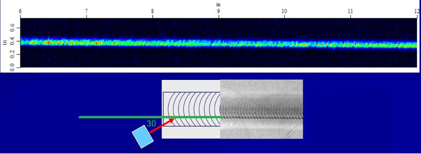
Metals 2019, 9, 624                                                                                       5 of 22

            Table 1. Standards and Specification for Friction Stir Welding (FSW) of Aluminum Alloys.

            Standard (Code)                                          Title
                                       American Welding Society (AWS)
                                         Specification for Friction Stir Welding of Aluminum Alloys for
       AWS D17.3/D17.3M:2010
                                                             Aerospace Applications
                                                    EN ISO
         EN ISO 25239-1:2011:               Friction Stir Welding—Aluminum—Part 1: Vocabulary
         EN ISO 25239-2:2011:           Friction Stir Welding—Aluminum—Part 2: Design of weld joints
         EN ISO 25239-3:2011:         Friction Stir Welding—Aluminum—Part 3: Qualification of welding
                                          Friction Stir Welding—Aluminum—Part 4: Specification and
         EN ISO 25239-4:2011:
                                                        qualification of welding procedures
                                       Friction Stir Welding—Aluminum—Part 5: Quality and inspection
         EN ISO 25239-5:2011:
                                                                requirements

4. Friction Stir Welding Process
      FSW differs in many ways from a traditional welding process and other jointing processes that
employ an external heat source. All heating that occurs with FSW is generated from the joining process
itself. In the analysis of this process there are many variables that are related to the heat generation and
input into the part during FSW such as traverse speeds, rotation speed, downward force, pin design,
and the tilt angle of the pin. These variables have a dependence on the properties of the material being
welded. This combination of parameters and material properties all interact and the interplay of the
relationships all affect the resultant weld properties in different ways. Through the optimization of
these parameters, FSW welds can exhibit high strengths, but may not always be defect free. When the
process is correctly designed, the optimum parameters allow for a stick-slip wiping flow where the
material flowing into the region ahead of the pin is balanced by the material flowing into the space
behind the tool [34].

4.1. Heat Generation
      FSW differs greatly from other welding processes in that there is no external heat source and
all of the heat involved in the joining process is generated through the tool-material interaction.
The tool action on the workpiece generates considerable stress and strain at the tool-workpiece
interface. The heat is primarily generated by high shear stresses and strain rates in the material at the
tool/workpiece interface [2]. For a given alloy and plate thickness with a particular tool, the primary
operating process variables which affect the heat generation phenomena are the pin geometry and
then the downward force, tool plunge depth, rotation speed, and traverse speed. The downward force
is a preset variable (if welding is not accomplished under position control), while the tool plunge
depth needed is defined by sample thickness. This leaves rotation speed and traverse speed as the
undefined process variables. Increased rotation speed leads to higher levels of heating and hence
temperatures induced in the material (Figure 3). Tang et al. (1998) performed a test in which the tool
rotation speed was varied and the resulting temperature of the weld in a 6061-T6 aluminum plate was
measured for various speeds; all other parameters were kept constant. At a tool rotation speed of
300 rpm, a temperature of 425 ◦ C was recorded. An increase to 650 rpm resulted in a 40 ◦ C increased to
465 ◦ C, and a further increase in speed to 1000 rpm resulted in a further increase of 20 ◦ C to 485 ◦ C [35].
Variation in the second key parameter, the transverse speed, is found to directly impact weld quality.
There is an optimal set of speed conditions with degraded welds occurring when the speed is either
too slow or too fast. When the transverse speed is too fast, occurrence of defects is common because
the pin moves too fast to give the time needed to properly mix the material and to generate the needed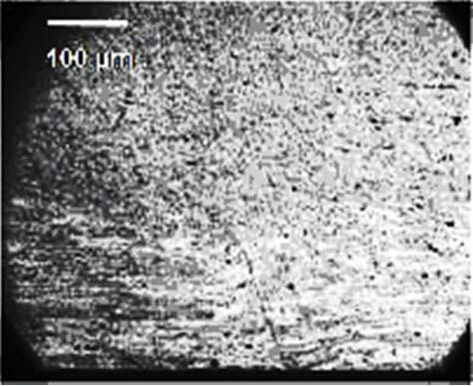
Metals 2019, 9, 624 6 of 22
level of heat input. A slow traverse speed will create too much heat within the weld and lead to
different
Metals 2019,forms
9, x; doi:ofFOR
defects, knows as
flash or voids [36].
PEER REVIEW 6 of 22
Figure 3. Tool rotation versus traverse welding speed showing heat generation. Reproduced with
Figure 3. Tool rotation versus traverse welding speed showing heat generation. Reproduced with
permission from [37], Elsevier, 2006.
permission from [37], Elsevier, 2006.
4.2. Tool Properties
4.2. Tool Properties
Tool properties such as geometry play a critical role in determining material flow and it controls
whatTool properties
is the optimal such as geometry
transverse speed play a critical
for good qualityroleweld
in determining
formation material
[38,39]. The flowtool
andisitdesigned
controls
what
with is the optimal
a shoulder andtransverse
a pin, asspeed
shown foringood quality
Figure 1 and weld formation
it has two main [38,39]. The tool
functions: to iscontrol
designedthe
with a shoulder and a pin, as shown in Figure 1 and it has two main functions:
material flow and generate heat. The pin and shoulder can be any one of multiple designs which to control the material
have
flow
beenand generatetoheat.
developed The pin
encourage theand shoulderofcan
formation the be any one
desired of multiple designs
microstructure whichmechanical
and resulting have been
developed to encourage the formation of the desired microstructure
properties. More modern tools are designed so as to reduce displaced volume. For example the and resulting mechanical
properties.
MX TrifluteMore moderndisplaced
pin reduces tools are designed
volume by so60%
as towhen
reduce displaced
compared to volume. For examplepins
earlier conventional the MX
[40].
Triflute pin reduces
The advances displaced
in design of thisvolume by 60%
tool reduces when force,
welding compared to earlier
enables easier conventional pins [40].
flow of plasticized The
material,
advances in design auguring,
creates downward of this tooland reduces welding
decreases force, enables
the interface easier flow
area between the of
pinplasticized material,
and the plasticized
creates downward auguring, and decreases the interface area between the
material [40]. Additional tool designs have been investigated so as to be able to perform various pin and the plasticized
material
functions[40]. Additional
during weldingtool designs
[41,42]. have beena tool
In producing investigated
design a so as to be able
combination to and
of life perform various
performance
functions during welding [41,42]. In producing a tool design a combination
parameters also need to be considered for a FSW processes so as to minimize the equipment costs of life and performance
parameters also the
associated with need to be considered
process [43]. for a FSW processes so as to minimize the equipment costs
associated with the process [43].
4.3. Effect of Anvil Back Plate
4.3. Effect of Anvil Back Plate
Anvil back plates have a significate effect of properties of FSW due to the interaction with the
Anvil
plunge back
force plates
as well as have a significate
influence effect of properties
on heat dissipation of FSWThe
of the process. dueinfluence
to the interaction with the
on heat dissipation
plunge force
will affect theasmicrostructure
well as influence on heat dissipation
evolution in the weldofnugget
the process. The influence on heat
and thermomechanically dissipation
affected zone.
will affect thethe
For example, microstructure
conventional evolution
steel anvilin theplates
back weld havenugget andthermal
a high thermomechanically
conductivity, whichaffected zone.
increases
For example, the
the dissipation conventional
of the generated heatsteel [44].
anvil back plates have a high thermal conductivity, which
increases the dissipation of the generated heat [44].
5. Mechanical Properties
5. Mechanical
There areProperties
a large number of studies which have been performed to evaluate mechanical and
material
Thereproperties in the
are a large weldof
number resulting
studies from use
which of FSW.
have beenThese have included
performed using
to evaluate experimental,
mechanical and
modeling
material and optimization
properties methods
in the weld [22].from use of FSW. These have included using experimental,
resulting
modeling and optimization methods [22].
5.1. Strength and Ductility
Many studies have been performed testing the ductility, tensile, and yield strength of material
in FSW welds, and the results are found to vary based on the FSW process parameters, post weld
heat treatments, and the materials involved. Mahoney et al. (1998) [24] tested the mechanical
properties of 7075-T651 aluminum using tensile specimens prepared in both transverse (across weld)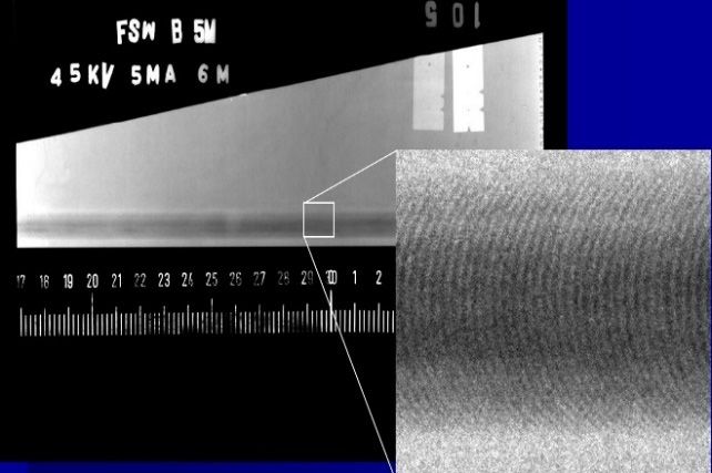
Metals 2019, 9, 624                                                                                    7 of 22

5.1. Strength and Ductility
     Many studies have been performed testing the ductility, tensile, and yield strength of material
in FSW welds, and the results are found to vary based on the FSW process parameters, post weld
heat treatments, and the materials involved. Mahoney et al. (1998) [24] tested the mechanical
properties of 7075-T651 aluminum using tensile specimens prepared in both transverse (across weld)
and longitudinal (along weld nugget) orientations. The longitudinal orientation samples retained 85%
tensile strength, 65% yield strength, and an equivalent elongation, when compared to base material.
A post-weld ageing treatment was reported to further decreased elongation and tensile strength but it
restored yield strength. The transverse orientation samples maintained 75% tensile strength, 55% yield
strength, but only half the elongation. It is not unexpected for the transverse orientation to have lower
values for mechanical properties, as it encompasses material from all the weld zones [24]. These results
have been verified in other studies and they are consistent with other reports that FSW materials
typically maintain 80% tensile strength and approximately 60% yield strength when compared to the
base metal properties. However, these data do not take into account the effects of various potential
cooling processes, different process parameters, and the use of different combinations of materials [45].
     When performing destructive tests and breaking the weld apart for the weld areas as defined
above, the strength metrics were almost constant in the weld nugget; the yield strength being ~80% of
the value for base materials and the ultimate strength was close to 100% with an addition improved
ductility. These properties are directly related to the grain size and structure in the weld nugget material.
When moving into the thermo-mechanically affected zone (TMAZ) the structure retains strength but
losses ductility. Finally, the heat affected zone (HAZ), as commonly found for many processes, is the
weakest zone for the weld. In HAZ material, the tensile strength can vary significantly with resulting
values as low as ~60% of the base material and consistently low ductility has also been reported [46].
It has further been reported that the strength and ductility for the advancing and retreating sides of the
weld are different, with the retreating side exhibiting lower strength [40], and this is consistent with
fractures always being found to occur on the retreating side, in transverse cut samples [47,48].

5.2. Fatigue
      With increasing use of FSW in industries, where fatigue life is of high importance, there has been
a lot of research to investigate fatigue properties and factors affecting fatigue life. When reviewed, it is
apparent that a few important observations have been reported, which are worth a mention. The fatigue
strength of the FSW weld material is lower than that of the base metal, thus the weld is susceptible to
being the site for fatigue crack initiation [49,50]. FSW butt welds have higher fatigue performance,
which generally exceeds that of comparable fusion welds for many alloy grades, and this is due to the
refined microstructure characteristics, which are found in FSW material [50,51]. Surface finish also
has a significant effect on fatigue life. The FSW process leaves a grooved surface, which creates the
possibility for crack initiation on the surface. In one study, Hori et al. (1999) [48] removed 0.5 mm from
the bottom and top sides of a weld in materials for use in subway rolling stock. This machining resulted
in observed strength increases in transverse and longitudinal material samples, which provided results
similar to the measured strength of the base metal. Furthermore, when Magnusson et al. (2000) [50]
removed a 0.5–15 mm layer from the top side by milling, he also found a significant improvement in
the fatigue life [52]. Similar results were found with various aluminum alloys including 6013, 2014 and
7475 [50,51]. It is noted that other factors also affect sample fatigue life, especially any residual stress,
the microstructure, and presence of defects which must also be accounted for when making fatigue life
comparisons [53,54].

5.3. Residual Stress
     Residual stresses are self-equilibrating forces in materials which occurred even in the absence of
external loads [55]. Residual stresses can have either detrimental or beneficial effects on structural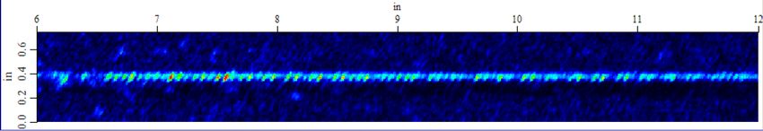
Metals 2019, 9, 624                                                                                     8 of 22

integrity and performance of the parts based on the location and exact nature of the stresses. Since
the magnitude of residual stresses can be as high as the yield strength of the materials, evaluation of
residual stresses found in FSW joints is crucial [56].

5.4. Hardness
      The mechanical properties of joints can be evaluated by measuring the hardness distribution.
In the case of FSW joints, measurements of the Vickers hardness is an appropriate method since values
can vary significantly over the region investigated [57]. It has been shown that dissolution and growth
of the precipitates during the thermal process of FSW can affect the hardness and consequently joint
efficiency [58]. Most of the hardness evaluations have been performed by first monitoring temperature
during FSW and then evaluating subsequent data in terms of its relationship to the microstructure and
hardness distributions. At higher temperatures (573 K in case of AA2024-T3), precipitates were found
to have started to dissolve and consequently the heat affected zone (HAZ) loses its hardness, resulting
in a reduction of joint efficiency. Precipitate growth time can be decreased by increasing the heating
rate and this then causes hardening in the HAZ [58].

5.5. Weld Microstructure
     The degree of heat generation which occurs during the joining process greatly alters the resulting
microstructure with four separate areas resultant when the material is examined and these are defined
by the American Welding Society (AWS) as:

1.    Base metal or unaffected metal: parent metal in which the microstructure and mechanical
      properties are the same as before the welding process.
2.    Heat affected zone (HAZ): volume close enough to the weld for thermal effects to modify the
      microstructure and/or mechanical properties but with no plastic deformation.
3.    Thermo-mechanically affected zone (TMAZ): This zone is identical to the HAZ but has plastic
      deformation. Recrystallization does in general occur but not for aluminum alloys.
4.    Stir zone: the area along the weld nugget in which the process passes through, recrystallization
      occurs for all materials in this zone [4].

      The weld nugget material is typically recrystallized and it has a fine and equiaxed grain
microstructure. There are also two shapes of the nugget zone: a basin shape that opens at the
top and an elliptical shape. Mishra et al. (2005) [39] reported that a basin shape is an artifact which
results from a lower tool rotation speed, typically between 300–500 rpm and an elliptical shape is due
to a tool rotation speed greater than 700 rpm [40].
      It is worth noting that a circular pattern called ‘onion rings’ are often seen in metallographic cross
sections in the weld nugget. The variations seen in the ring pattern, according to Mishra et al. [40],
are due to differences in dislocation density and texture effects. This is not believed to be a complete
explanation for the rings, but it is further thought that they are associated with effects due to the rotation
of the tool, as well as being associated with the direct function of tool geometry, and process rotation
and traverse travel speeds [40,59]. Notably, in aluminum materials subject to FSW, crystallization
occurs within the weld nugget and it isn’t unusual to finish with equiaxed grain sizes on the order of a
few micrometers. It is also possible to control grain size by use of external cooling or altering various
process parameters. In metallographic examinations, it is common to see larger grains at the top of the
weld due to the effects of heat dissipation through the backing plate and as a result of the lower peak
temperatures at the bottom of the weld [40,60].

6. Types of Defects
     With adequate process control, the FSW process is often capable of effectively eliminating, or at
least significantly reducing, the occurrence of many of the defects, which are associated with fusion
welding techniques such as shrinkage, solidification cracking and porosity. However, as in any weld,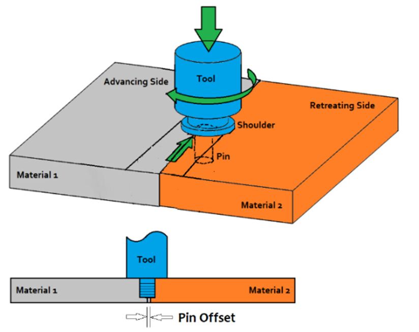
Metals 2019, 9, 624                                                                                      9 of 22

some defects can occur which are dependent on the joint geometry (butt or lap), but each type of defect
does not affect the material in the same way and therefore must be understood if it is to be identified
and then prevented by process modifications [61]. There are still various types of defects that can occur
during the FSW process irrespective of the welding orientation.
Metals 2019, 9, x; doi: FOR PEER REVIEW                                                                  9 of 22
6.1. Wormhole
     Wormhole defects are in the form of voids or trailing voids left in the material after the welding
     Wormhole defects are in the form of voids or trailing voids left in the material after the welding
process. Such defects are caused by abnormal material flow conditions during welding resulting from
process. Such defects are caused by abnormal material flow conditions during welding resulting from
sub-optimal combinations of numerous factors including stirring rotational speed, traverse speed,
sub-optimal combinations of numerous factors including stirring rotational speed, traverse speed,
resulting heat generation, and shoulder pressure. This type of defect can be prevented by using pins
resulting heat generation, and shoulder pressure. This type of defect can be prevented by using pins
with a design optimized to match the weld material and thickness or adjusting the welding process
with a design optimized to match the weld material and thickness or adjusting the welding process
parameters [62,63]. Kahl (2013) [45] evaluated the occurrence of wormhole voids along the weld
parameters [62,63]. Kahl (2013) [45] evaluated the occurrence of wormhole voids along the weld
nugget in 6061-T6 aluminum and observed a decrease of 10% of tensile strength and a large reduction
nugget in 6061-T6 aluminum and observed a decrease of 10% of tensile strength and a large reduction
in elongation when wormholes occur. For the same material fatigue testing between 42.5–57.5 MPa
in elongation when wormholes occur. For the same material fatigue testing between 42.5–57.5 MPa
stress amplitude the samples exhibited a decrease of ~20% in lifetime for those welds which contained
stress amplitude the samples exhibited a decrease of ~20% in lifetime for those welds which contained
small voids [45].
small voids [45].
6.2. Lack of Penetration (LOP)
6.2. Lack of Penetration (LOP)
      Lack of penetration (LOP) defects are found in butt welds, where the lower portion of the joined
      Lack of penetration (LOP) defects are found in butt welds, where the lower portion of the joined
interface is only partially disrupted (Figure 4). This is caused by the FSW pin not being long enough
interface is only partially disrupted (Figure 4). This is caused by the FSW pin not being long enough to
to penetrate both materials effectively, and it can be prevented by using a pin design which is
penetrate both materials effectively, and it can be prevented by using a pin design which is optimized
optimized for the specific weld application and by keeping the shoulder of the tool flush with the
for the specific weld application and by keeping the shoulder of the tool flush with the material
material surface [64].
surface [64].

                      Lack of
            Figure 4. Lack of penetration
                              penetration defect
                                          defect where
                                                 where the pin does not penetrate material completely.

     An
     An example
         example ofof LOP
                      LOP defects,
                           defects, which were caused
                                    which were caused byby change
                                                           change inin welding
                                                                       welding tool
                                                                                 tool rotational
                                                                                      rotational speed
                                                                                                 speed and
                                                                                                       and
pressure (load), are seen in the metallography of 3.175 mm   (0.125  in) thick Aluminum    7075-T73
pressure (load), are seen in the metallography of 3.175 mm (0.125 in) thick Aluminum 7075-T73 panelspanels
shown
shown in
       in Figure
          Figure 55 [65].
                    [65].
6.3. Partial and Kissing Bonds
6.3. Partial and Kissing Bonds
      Partial and kissing bonds (KB) typically occur in the root of the weld. This type of defect arises
      Partial and kissing bonds (KB) typically occur in the root of the weld. This type of defect arises
when two adjacent surfaces are in close contact, but never form a full metallurgical bond [66], giving
when two adjacent surfaces are in close contact, but never form a full metallurgical bond [66], giving
reduced strength. The kissing bond can have surfaces in contact and no metallurgical joining. This is
reduced strength. The kissing bond can have surfaces in contact and no metallurgical joining. This is
due to insufficient deformation of the joining surface interface due to incorrect tool design, lack of
due to insufficient deformation of the joining surface interface due to incorrect tool design, lack of
penetration, poor surface preparation, residual stress, contamination, or some combinations of these
penetration, poor surface preparation, residual stress, contamination, or some combinations of these
factors [67]. The effect of KB on the static strength of the weld can be negligible, and depends on the
factors [67]. The effect of KB on the static strength of the weld can be negligible, and depends on the
application. However, KB defects can significantly reduce the fatigue life depending on the size of the
application. However, KB defects can significantly reduce the fatigue life depending on the size of
KB defect area [68]. For example, Kadlec (2015) [46] performed mechanical testing to investigate the
the KB defect area [68]. For example, Kadlec (2015) [46] performed mechanical testing to investigate
effects of the KB defects on tensile and fatigue properties of 7475-T7351 friction stir welds against welds
the effects of the KB defects on tensile and fatigue properties of 7475-T7351 friction stir welds against
without any flaws. Various KB defects were investigated by Kadlec with the aim of evaluating which
welds without any flaws. Various KB defects were investigated by Kadlec with the aim of evaluating
which defect geometry has no influence to the fatigue life of joined 6.35 mm thick plates. A critical
value for KB geometry seemed to be 0.3 mm in depth considering influence on fatigue life for
investigated configurations. It was reported that samples with shorter kissing bonds allowed higher
elongation values and higher tensile strength. It was also reported that when a kissing bond ‘open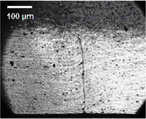
Metals 2019, 9, 624                                                                                          10 of 22

defect geometry has no influence to the fatigue life of joined 6.35 mm thick plates. A critical value
for KB geometry seemed to be 0.3 mm in depth considering influence on fatigue life for investigated
configurations. It was reported that samples with shorter kissing bonds allowed higher elongation
values and higher tensile strength. It was also reported that when a kissing bond ‘open ups’, it caused
fracture before necking could start. This study showed the detrimental effects of having kissing bonds
in welds
Metals 2019,in
             9, x;structure   materials
                    doi: FOR PEER REVIEW[46]. When using conventional NDT techniques the detection  and
                                                                                                 10 of 22
determination of an accurate size for the KB defect is a difficult task.

               LOP Depth (inches) = 0.0097                              LOP Depth (inches) = 0.0102

               LOP Depth (inches) = 0.0122                              LOP Depth (inches) = 0.0210

      Figure 5. Metallography
                Metallography of
                              of lack
                                 lack of
                                      of penetration
                                         penetration (LOP)
                                                     (LOP) defects
                                                           defects in 3.175
                                                                      3.175 mm
                                                                            mm (0.125
                                                                               (0.125 in) thick
                                                                                          thick AL
                                                                                                AL 7075-T73
                                                                                                   7075-T73
      panels. Reproduced
              Reproduced with permission from [69], Taylor & Francis,
                                                               Francis, 2019.
                                                                         2019.

6.4. Hooking
6.4. Hooking Bonds
             Bonds
     Hooking Bonds
     Hooking     Bonds are
                         are defects
                             defects that
                                      that are
                                            are specific
                                                specific to
                                                         to lap
                                                            lap joints,
                                                                 joints, and
                                                                         and they
                                                                              they are
                                                                                    are formed
                                                                                        formed when
                                                                                                 when the
                                                                                                       the interface
                                                                                                           interface
between the
between    thetwo
                twoadjoining
                      adjoiningsheets
                                  sheets   is stirred
                                        is stirred up up
                                                       intointo   the sheet,
                                                             the top   top sheet,
                                                                              whichwhich   effectively
                                                                                     effectively       reduces
                                                                                                 reduces          the
                                                                                                          the cross-
cross-sectional   area  of the  sheet.  It is found  that  the  two  main    causes  of hooking   defects
sectional area of the sheet. It is found that the two main causes of hooking defects are lower transverse are  lower
transverse
welding      welding
          speed         speed rotational
                  and higher   and higher     rotational
                                            speed.        speed. can
                                                    Such defects    Suchbedefects  can with
                                                                            prevented   be prevented   with double
                                                                                             double passing   welds
passing   welds   and   by  overlapping     the  advancing     sides  [21].  In designing
and by overlapping the advancing sides [21]. In designing a welding system the appropriate  a welding   system    the
appropriate    geometry    and   shape  of  the FSW   tool  should   be  obtained   to minimize
geometry and shape of the FSW tool should be obtained to minimize potential for this defect in thepotential  for this
defect insheet
bottom     the bottom
                of a lapsheet
                         joint of a lap joint [70].
                               [70].

6.5. Cracks
     Cracks can be generated in the welding zone of FSW by various factors. Among the causes of
cracking are excessive local load and stress concentration that can generate cracks in the welding area
due to high thermal stresses [51]. Resulting residual stresses and heat-affected zone properties can
also influence crack formation and propagation in FSW joints [51]. Furthermore, development of the
microstructures which occur in the weldment during the FSW process affects crack growth due to
both corrosion or fatigue [71]. Another mechanism involved with crack generation in FSW is Liquid
Metals 2019, 9, 624 11 of 22
6.5. Cracks
Cracks can be generated in the welding zone of FSW by various factors. Among the causes of
cracking are excessive local load and stress concentration that can generate cracks in the welding area
due to high thermal stresses [51]. Resulting residual stresses and heat-affected zone properties can
also influence crack formation and propagation in FSW joints [51]. Furthermore, development of the
microstructures which occur in the weldment during the FSW process affects crack growth due to
both corrosion or fatigue [71]. Another mechanism involved with crack generation in FSW is Liquid
Penetration Induced (LPI) cracking. The liquid penetration induced cracking mechanism has been
studied for a variety of alloys and situations. For example, Yamamoto et al. (2007) [72] explained
that LPI cracking in magnesium alloy AZ91 results from the following sequence of events: melted
eutectic film formation in the periphery of the stir zone region, subsequent engulfing of melted eutectic
films when the stir zone grows in width during the dwell period, and then penetration of α-Mg grain
boundaries in the stir zone extremity and crack propagation when torque is applied by the rotating
tool [72,73].
7. Material Evaluation and Quality Control of FSW
Increasing and widespread industrial application of FSW is still limited by the potential risk for
generation of defects that can occur during the process. Consequently, the ability to reliably detect
relatively small flaws and determine associated mechanical properties are important for quality control
and in the definition of acceptance standards for FSW joined material. To define what types and sizes
of acceptable anomalies are, a variety of techniques can be employed for the evaluation of the quality
of FSW joints and associated mechanical properties. These techniques can be categorized into both
destructive and nondestructive methods.
7.1. Destructive Testing and Evaluation Methods
Variations in the FSW process parameter directly affect the microstructure and mechanical
properties of the resulting joint [74]. For the material, the stress-strain curve and Young modulus of the
FSW can be determined by conventional tensile tests. Either standard flat or cylindrical dog-bone shape
samples are used for these tests. In case of FSW, flat dog-bone shape samples are being used. Tensile,
bending and fatigue performance of the FSW material are subjected to different loading conditions and
the resulting data are used to understand the mechanical behavior of the joints [75–77]. Metallographic
examinations can also reveal details of microstructure and some types of defects in FSW material such
as lack of penetration and kissing bonds [64].
7.2. Non-Destructive Testing and Evaluation Methods for FSW
As with other forms of welds, a range of nondestructive testing (NDT) methods have been used
extensively to detect and characterize flaws in FSW joints. Application of each NDT method depends
on knowledge regarding the desired application, needed joint and material properties, possible types of
defects and geometry of the joint and specimens [78]. Also, in assessing effectiveness of an inspection
method, the detectability or Probability of Detection (POD) for each method and class of defects needs
to be evaluated.
7.2.1. Radiography (X-Ray Imaging and Computed Tomography (CT))
X-ray radiography produces images that are potentially useful for detecting defects when there
are significant differences in radiation absorption between an anomaly and the surrounding parent
material. Thus, when the digital detector measures variations in radiation flux these are displayed as
darker or lighter regions on the displayed image which correspond to regions of either higher or lower
absorption. For larger and complex parts in many metals, this method has penetration limitationsMetals 2019, 9, 624 12 of 22
which vary with the different absorption coefficients of the materials. The penetration capabilities also
depend on the power of the X-ray system and inspection time employed.
In general terms, radiography works well for detecting volumetric flaws, of certain classes, after
production, but is be difficult and costly to implement into an in-line manufacturing process [69,79].
Examples of successful applications include work by Saravanan et al (2014) [80] who used a
micro-focused X-ray imaging technique to detect micro-pores and voids in FSW of dissimilar material
lap joints (150 × 100 mm), which were fabricated using 2 mm thick aluminum (grade 6061) and
zinc coated steel (SS 316) sheet of 1 mm thickness [80]. Gray et al. (2008) [65] demonstrated X-ray
radiography for detection of wormhole defects in different FSW sample panels [65]. The wormholes
detected were as small as 0.0017 mm2 in 6.35 mm (0.25 in) thick panels and 0.001 mm2 in 3.175 mm
(0.125 in) thick panels and examples of such features are shown in Figure 6. The sizes of the defects
were measured by metallography and are categorized as “very small: 0.0007 mm2 ”, “small: 0.001
mm2 ”, and “large: 0.0472 mm2 ”. However, it was mentioned that the shape and size of the welded
Metals 2019, 9, x; doi: FOR PEER REVIEW 12 of 22
parts and surface finish are in general the most challenging factors limiting defect detection when
using aa radiography
using radiography technique.
technique. The
The assessment
assessmentof of the
the POD
POD versus
versus defect
defect size
size characteristic
characteristic is
is also
also
challenging to
challenging to estimate,
estimate, particularly
particularly due
due to
to the
the effects
effects of
of the
the complex
complex geometric
geometric nature
nature of
of the
the welds
welds
and the difficulty faced with reliably identifying and determining the size
and the difficulty faced with reliably identifying and determining the size of defects. of defects.
(a) (b)
(c) (d)
Figure
Figure 6. Inspection
Inspection of of friction
friction stir
stir welded
welded panels
panels using
using X-ray
X-ray radiography
radiography method
method forfor detection
detection of
of
wormhole defects:
defects: (a)
(a)no
nodefect,
defect,
(b)(b) very
very small
small defect
defect (tiny(tiny
blackblack
spotsspots
in leftin left
side of side of zoomed
zoomed in
in section),
(c) small (c)
section), defect,
smalland (d) large
defect, defect
and (d) [65].
large defect [65].
7.2.2. Thermography
7.2.2. Thermography
Thermography produces
Thermography producesimages
imageswith
withananinspection
inspection employing
employing a contrast
a contrast mechanism
mechanism based
based on
on thermal property variations due to geometrical anomalies, material loss, inclusions, and
thermal property variations due to geometrical anomalies, material loss, inclusions, and voids. voids.
Thermography is a non-contact and potentially full-field methodology, making it a good candidate
for in-line monitoring. Due to the heat generation mechanisms which occur in the FSW process [81],
thermographic techniques can be used to find defects in real-time during the welding process [82]. In
such real-time monitoring, thermal behavior of joints can be correlated to process parameters and
thermography can hence be used to perform online monitoring of the FSW process. There is aMetals 2019, 9, 624 13 of 22
Thermography is a non-contact and potentially full-field methodology, making it a good candidate
for in-line monitoring. Due to the heat generation mechanisms which occur in the FSW process [81],
thermographic techniques can be used to find defects in real-time during the welding process [82].
In such real-time monitoring, thermal behavior of joints can be correlated to process parameters
and thermography can hence be used to perform online monitoring of the FSW process. There is a
possibility that this technique could be implemented to detect flaws as they are being created during
welding and the FSW tool control system would then be able to potentially proactively correct defects
on the part, before items move further along a production line [83].
7.2.3. Eddy Current
Eddy current NDT methods can be used for inspection of electrically conductive materials.
A limiting factor for this inspection method is the depth of penetration of the electric field used to
detect anomalies, which limits its use to detection of surface and near surface defects. Conventional
and pulsed eddy current techniques can both be used for testing. In conventional eddy current
testing, a sinusoidal waveform is used for excitation, while the response signals are represented on an
impedance plane diagram, as changes in the resistive and reactive components of the impedance give
the combined response of the coil, field and material. Pulsed eddy current measurements, in general,
use a square waveform to drive the excitation coil instead of a sinusoidal wave excitation, which is
more typically used in conventional eddy current testing. Generally, pulsed methods are capable of
probing deeper into the material than the conventional eddy current methods. Another significant
difference between conventional and pulsed eddy current measurements is that the signals in the latter
case are recorded in the time domain and not on an impedance plane diagram [64,84]. New advances
in eddy current probes and electronic devices now provide the capability to detect superficial defects
at variety of depth depending on the frequency [85].
7.2.4. Ultrasonic Testing
Ultrasonic testing, in a variety of forms including acoustic microscopy have been widely used
to detect and characterize defects in FSW and other solid-state welded interfaces [86,87]. In these
methods, both compression and shear wave excitation have been used in various studies for inspection
of FSW [88,89]. Stepinski et al. (2004) [90] prepared an excellent review on advanced ultrasound
techniques for inspection of FSW with an introduction to other NDE techniques that can potentially be
used and for illustrations mostly used results from the aerospace industry [90]. The main challenge
which limits using ultrasonic techniques, specifically with contact and immersion methods, is the
surface finish for FSW. For this reason, most inspections need to be performed with access from the
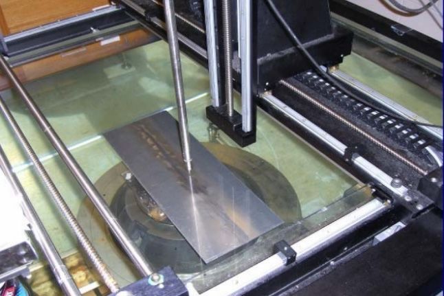
back of the weld or after surface preparation, which involves a machining process. An example of
the experimental setup and schematic configuration which was used by Gray et al. (2008) [65] for the
ultrasonic inspection of FSW panels with wormhole defects is shown in Figure 7 [65]. The C-scan
ultrasonic immersion results were obtained when using 45◦ shear wave with a 10 MHz 75 mm (3”)
focal length probe skewed at approximately 30◦ (azimuth) from weld line, showing examples for
“very small: 0.0007 mm2 ”, and “large: 0.0472 mm2 ” wormhole defect sizes which could be detected
(Figure 8).An example
(2008) [65] for ofthe
theultrasonic
experimental setup and
inspection schematic
of FSW panelsconfiguration
with wormholewhich wasisused
defects shownby in
Gray et al.7
Figure
(2008) [65]C-scan
[65]. The for theultrasonic
ultrasonicimmersion
inspectionresults
of FSWwere
panels with wormhole
obtained defects
when using is shown
45° shear waveinwith
Figure
a 107
[65]. The C-scan ultrasonic immersion results were obtained when using 45° shear wave
MHz 75 mm (3”) focal length probe skewed at approximately 30° (azimuth) from weld line, showing with a 10
MHz 75 mm
examples for(3”) focal
“very length
small: probe
0.0007 mm skewed
2”, and at approximately
“large: 0.0472 mm30° (azimuth) from
2” wormhole defectweld
sizesline, showing
which could
examples for “very
be detected (Figure 8).
Metals 2019, 9, 624 small: 0.0007 mm 2”, and “large: 0.0472 mm2” wormhole defect sizes which 14 could
of 22
be detected (Figure 8).
(a) (b)
(a) (b)
Figure 7. Inspection of FSW panels with wormhole defects (a) Experimental setup, and (b) schematic
Figure 7. Inspection
for theof
Inspection
configuration of FSW
FSW panels
ultrasonic with wormhole
inspection. [65]. defects (a) Experimental setup, and (b) schematic
configuration for the ultrasonic inspection. [65].
Metals 2019, 9, x; doi: FOR PEER REVIEW 14 of 22
(a)
(a)
(b)
Figure 8. Immersion C-scan ultrasonic imaging at 10 MHz using 45 45°◦ shear wave with probe skewed
approximately 30 ◦
30° (azimuth) from weld line
line for
for (a)
(a) “very
“very small:
small: 0.0007 mm22”, and (b) “large:
0.0007 mm “large: 0.0472
mm22”wormhole
”wormhole defect sizes [65].
Phased
Phased Array
Array
Phased
Phased array
array ultrasonic testing (PAUT)
ultrasonic testing (PAUT) is is aa form
form of
of testing,
testing, which
which differs
differs from
from other
other ultrasonic
ultrasonic
testing (UT) methods in the way the wave field is generated and detected.
testing (UT) methods in the way the wave field is generated and detected. It employs It employs an ultrasonic array
an ultrasonic
probe that is typically composed of 16 to 256 elements, each acts as a single transducer.
array probe that is typically composed of 16 to 256 elements, each acts as a single transducer. These These elements
are arranged
elements as a string,
are arranged as ring, or circular
a string, ring, or matrix
circularand can and
matrix be fired singularly
can be or together
fired singularly to formto
or together a
designed wave front. The resulting beam can then be modified by changing
form a designed wave front. The resulting beam can then be modified by changing the amplitude the amplitude and timing
of
andthe excitation
timing of thepulse sent topulse
excitation eachsent
element [91,92].
to each element [91,92].
In
In implementations of PUAT there are three main
implementations of PUAT there are three main electronic
electronic scanning
scanning methods: linear, dynamic
methods: linear, dynamic
depth focusing or swept angular scanning [93,94]. Swept or sectorial scanning,
depth focusing or swept angular scanning [93,94]. Swept or sectorial scanning, has proven successfulhas proven successful
in
in FSW
FSWapplications
applications[95,96].
[95,96].PAUT
PAUT hashas
broad application
broad in FSW
application quality
in FSW controlcontrol
quality and inspection [79,97].
and inspection
For defect detection in FSW, sectorial scanning has generally been used. This
[79,97]. For defect detection in FSW, sectorial scanning has generally been used. This is where the is where the beam is
moved through a sweep range for a specific depth, additional focal depths can
beam is moved through a sweep range for a specific depth, additional focal depths can be added for be added for the same
element,
the same which produces
element, which aproduces
shear wave. Thiswave.
a shear method Thishas been applied
method has been inapplied
the 4–10inMHz frequency
the 4–10 MHz
frequency range [98], and in process this should be targeted on the advancing side of the weld, as this
is the region where defects in general form.
PAUT has gained industry acceptance as a reliable and accurate detection method and is now
commonly implemented throughout industry because it potentially offers increased inspection
sensitivity and good coverage, as well being applicable in near-real time. Additionally, it allows forYou can also read