ISim Hardware Co-Simulation Tutorial: Processing Live Ethernet Traffic through Virtex-5 Embedded Ethernet MAC
←
→
Page content transcription
If your browser does not render page correctly, please read the page content below
ISim Hardware Co-Simulation
Tutorial:
Processing Live Ethernet
Traffic through Virtex-5
Embedded Ethernet MAC

UG819 (v 13.2) July 28, 2011
Xilinx is disclosing this user guide, manual, release note, and/or specification (the “Documentation”) to you
solely for use in the development of designs to operate with Xilinx hardware devices. You may not reproduce,
distribute, republish, download, display, post, or transmit the Documentation in any form or by any means
including, but not limited to, electronic, mechanical, photocopying, recording, or otherwise, without the prior
written consent of Xilinx. Xilinx expressly disclaims any liability arising out of your use of the Documentation.
Xilinx reserves the right, at its sole discretion, to change the Documentation without notice at any time. Xilinx
assumes no obligation to correct any errors contained in the Documentation, or to advise you of any corrections
or updates. Xilinx expressly disclaims any liability in connection with technical support or assistance that may be
provided to you in connection with the Information.
THE DOCUMENTATION IS DISCLOSED TO YOU “AS-IS” WITH NO WARRANTY OF ANY KIND. XILINX
MAKES NO OTHER WARRANTIES, WHETHER EXPRESS, IMPLIED, OR STATUTORY, REGARDING
THE DOCUMENTATION, INCLUDING ANY WARRANTIES OF MERCHANTABILITY, FITNESS FOR A
PARTICULAR PURPOSE, OR NONINFRINGEMENT OF THIRD-PARTY RIGHTS. IN NO EVENT WILL
XILINX BE LIABLE FOR ANY CONSEQUENTIAL, INDIRECT, EXEMPLARY, SPECIAL, OR INCIDENTAL
DAMAGES, INCLUDING ANY LOSS OF DATA OR LOST PROFITS, ARISING FROM YOUR USE OF THE
DOCUMENTATION.
© Copyright 2002-2011 Xilinx Inc. All Rights Reserved. XILINX, the Xilinx logo, the Brand Window and other
designated brands included herein are trademarks of Xilinx, Inc. All other trademarks are the property of their
respective owners. The PowerPC name and logo are registered trademarks of IBM Corp., and used under license.
All other trademarks are the property of their respective owners.

                                                                                  Processing Live Ethernet Traffic
2                                                www.xilinx.com                       UG819 (v 13.2) July 28, 2011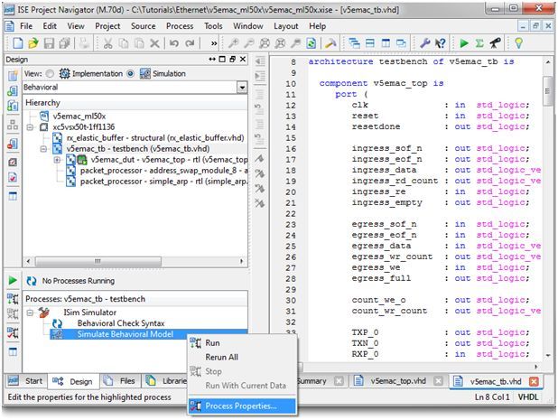
Table of Contents
       Chapter 1      Introduction ............................................................................................... 5
               Prerequisites......................................................................................................... 6
               Tutorial Files......................................................................................................... 7

       Chapter 2      Tutorial ....................................................................................................... 9
               Generating a Design in CORE Generator........................................................... 9
               Creating a Test Bench........................................................................................... 22
               Step 1: Generating a Design in CORE Generator .............................................. 22
               Step 2: Creating a Test Bench .............................................................................. 34
               Step 3: Creating a Custom Constraints File........................................................ 34
               Step 4: Compiling the Design for Hardware Co-Simulation ............................ 37
               Step 5: Running ISim Hardware Co-Simulation ............................................... 40

       Appendix       Additional Resources ...............................................................................45

Processing Live Ethernet Traffic
UG819 (v 13.2) July 28, 2011                               www.xilinx.com                                                                  3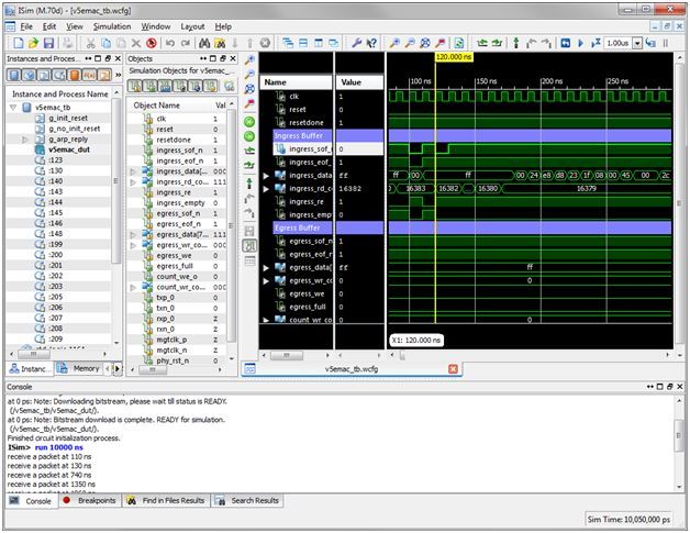
Processing Live Ethernet Traffic
4   www.xilinx.com       UG819 (v 13.2) July 28, 2011
Chapter 1

Introduction
                         This tutorial describes how to use ISim hardware co-simulation to capture live Ethernet
                         traffic through the Virtex®-5 FPGA Embedded Tri-mode Ethernet MAC and process the
                         captured packets from your HDL test bench at run-time.
                         When developing an FPGA design that uses Ethernet, it is often challenging to verify
                         the whole design including the Ethernet MAC, Multi-Gigabit Transceivers (if SGMII is
                         used to interface between the Ethernet MAC and PHY), and Ethernet PHY. Traditionally,
                         we either simulate the whole design in software, or run the whole design in hardware.
                         A full software simulation approach is useful in two aspects. It offers full visibility
                         into the design and allows the test bench or design to be changed and re-verified in a
                         rapid manner. The challenges, however, are setting a test bench that covers the Ethernet
                         MAC, MGT, and PHY, and achieving a reasonable simulation speed. Very often we
                         skip various details on the simulation of MGT and PHY, or bypass them altogether. In
                         contrast, running the design in hardware addresses these problems, but at the cost of
                         reduced visibility into the design, and the complexity to set up and change the test
                         bench in hardware.
                         ISim hardware co-simulation is a third option in your toolbox. It gives you the flexibility
                         to run a portion of your design in hardware while simulating the rest in software. The
                         Ethernet MAC, MGT and PHY are, for example, good candidates to put in hardware so
                         that they are modeled exactly and simulated quickly. The test bench and the application
                         logic such as the packet processor in your design, which are under development,
                         should be simulated in software so you can change, verify and debug them easily and
                         rapidly. Figure 1-1 on page 5 shows how a design for Ethernet packet processing can be
                         partitioned to leverage the ISim hardware co-simulation features.

Processing Live Ethernet Traffic
UG819 (v 13.2) July 28, 2011                     www.xilinx.com                                                   5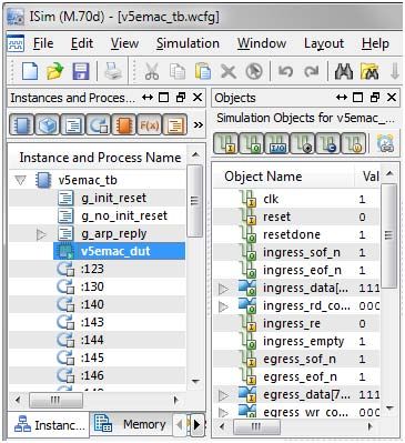
Chapter 1: Introduction

           Partitioning an Ethernet Design for ISim Hardware Co-Simulation

Prerequisites
                          This tutorial requires the following software and hardware:
                          •   ISE® Design Suite, version 13.2
                          •   Virtex®-5 ML506 Evaluation Kit
                          •   Design File: rdf0127_ live_emac_tutorial.zip
                          Note Please refer to the ML506 Evaluation Platform User Guide (UG347) to connect
                          your ML506 board to your PC using a JTAG cable. In this tutorial, we use the SGMII
                          mode to interface with the Ethernet PHY. As shown in the following figure, you need to
                          change the jumper J22, J23 and J24 on the ML506 board to select SGMII as the default
                          PHY interface.

                                           PHY Interface Mode Jumpers on ML506

                          •   J22: Jumper over pins 2-3
                          •   J23: Jumper over pins 2-3
                          •   J24: No jumper

                                                                                 Processing Live Ethernet Traffic
6                                                 www.xilinx.com                     UG819 (v 13.2) July 28, 2011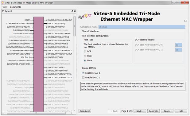
Chapter 1: Introduction

Tutorial Files
                          File                      Description
                          v5emac_top.vhd            Wrapper that instantiates the Ethernet MAC core, ingress FIFO,
                                                    egress FIFO, and packet count FIFO.
                          v5emac_tb.vhd             Top-level test bench that instantiates the packet processor.
                          simple_arp.vhd            A sample packet processor that responds to ARP requests.
                          v5emac_hwcosim.ucf        Custom constraints file for hardware co-simulation that indicates
                                                    which ports on the v5emac_top module to be mapped to external
                                                    I/Os and which ports are controlled from the test bench.
                          v5emac_ml50x.xise         ISE project for this tutorial.
                          ipcore_dir                CORE Generator™ directory that contains the Virtex®-5
                                                    Embedded Tri-mode Ethernet MAC Wrapper and FIFO cores.
                          init.tcl                  Custom simulation command file that tells ISim to initialize the
                                                    simulation.
                          v5emac_tb.wcfg            Custom waveform configuration file.
                          v5emac_tb.prj             Hardware co-simulation board support file for PEEP.
                          v5emac_tb.prj             Windows batch file to fully compile the design for hardware
                                                    co-simulation with the Fuse command line.
                          full_compile.sh           Linux shell script to fully compile the design for hardware
                                                    co-simulation with the Fuse command line.
                          incr_compile.bat          Windows batch file to incrementally compile the test bench for
                                                    hardware co-simulation with the Fuse command line.
                          incr_compile.sh           Linux shell script to incrementally compile the test bench for
                                                    hardware co-simulation with the Fuse command line.
                          run_isim.bat              Windows batch file to launch the ISim simulation.
                          run_isim.sh               Linux shell script to launch the ISim simulation.

                         Note As you work through this tutorial, you must copy all data files to your current
                         working directory.

Processing Live Ethernet Traffic
UG819 (v 13.2) July 28, 2011                    www.xilinx.com                                                          7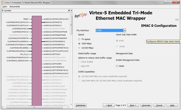
Processing Live Ethernet Traffic
8   www.xilinx.com       UG819 (v 13.2) July 28, 2011
Chapter 2

Tutorial
                         This tutorial is separated into five sections that contain the steps you need to perform
                         to run an Ethernet design through ISim hardware co-simulation. Perform the steps in
                         the order that they are presented.
                         This tutorial contains the following sections:
                         1.   Generate a Virtex®-5 Ethernet MAC example design using the Virtex-5 Embedded
                              Tri-mode Ethernet MAC Wrapper in CORE Generator™.
                         2.   Create a test bench to binds the Ethernet MAC wrapper to a packet processor.
                         3.   Create a custom constraints file to specify which ports on the example design are
                              controlled by ISim and which are mapped to external I/Os.
                         4.   Compile the test bench for ISim simulation with the example design targeted for
                              hardware co-simulation.
                         5.   Connect the target FPGA board to your PC and run the ISim simulation.

Generating a Design in CORE Generator
                         The Virtex-5 FPGA has an embedded tri-mode Ethernet MAC (EMAC) block, which
                         provides a simple and reliable way to interface with an Ethernet PHY interface. The
                         Virtex-5 Embedded Tri-mode Ethernet MAC Wrapper in CORE Generator simplifies
                         the configuration of the Ethernet MAC block. In this tutorial, we are going to use the
                         example design generated by the CORE Generator tool and create an ISim hardware
                         co-simulation test bench that runs on the Virtex-5 FPGA ML506 Evaluation Kit.
                         Note The screen captures in this tutorial are based on the Virtex-5 Embedded Tri-mode
                         Ethernet MAC Wrapper version 1.8. The CORE Generator GUI may look different in
                         later versions of the tool.
                         1.   Launch the ISE® Project Navigator.
                         2.   Choose File > New Project to open the New Project Wizard. Enter a project name
                              (v5emac_ml50x) and location. Click Next.

Processing Live Ethernet Traffic
UG819 (v 13.2) July 28, 2011                     www.xilinx.com                                                     9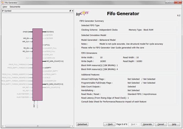
Chapter 2: Tutorial

                      3.   On the Project Settings page, choose the part for the ML605 board, which is Virtex-5
                           device XC5VSX50T, package FF1136, and speed -1. Select ISim as the simulator
                           and VHDL as the preferred language. Click Next and then Finish to complete
                           the project creation.

                      4.   Choose Project > New Source to open the New Source Wizard. Select IP (CORE
                           Generator & Architecture Wizard) and name the IPv5emac. Click Next.

                                                                               Processing Live Ethernet Traffic
10                                             www.xilinx.com                      UG819 (v 13.2) July 28, 2011
Chapter 2: Tutorial
5. Select Virtex-5 Embedded Tri-mode Ethernet MAC Wrapper version 1.8 or later
from the IP list. Click Next and then Finish.
6. When the Virtex-5 Embedded Tri-Mode Ethernet MAC Wrapper dialog box opens,
set the Host Type to None. Make sure Enable EMAC 0 is checked and Enable
EMAC 1 is unchecked. Click Next.
Processing Live Ethernet Traffic
UG819 (v 13.2) July 28, 2011 www.xilinx.com 11Chapter 2: Tutorial
7. Set Phy Interface to SGMII, and the Speed to 1000 Mbps. Leave the MDIO check
box unchecked. Click Next.
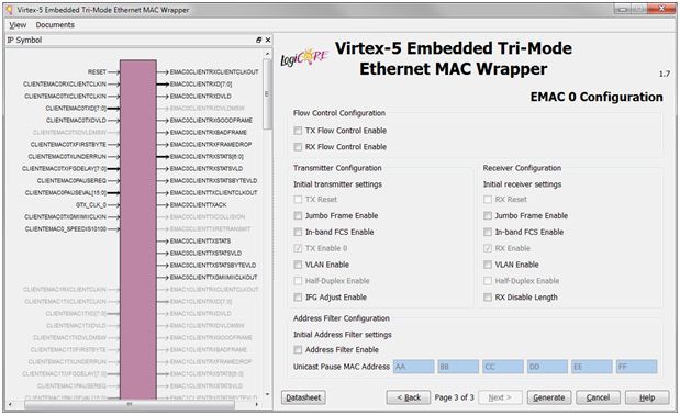
8. Use the default settings for the flow control, transmitter, receiver, and address filter
configuration. Click Generate to generate the core.
Processing Live Ethernet Traffic
12 www.xilinx.com UG819 (v 13.2) July 28, 2011Chapter 2: Tutorial
Note After the Ethernet MAC wrapper core is generated, we use the
LocalLink submodule v5emac_locallink in example design generated in the
ipcore_dir/v5emac/example_design directory.
In this tutorial, we do not use the entire example design v5emac_example_design,
since we need to partition the design into two asynchronous halves, one simulated
in lock-step with the ISim test bench and the other free-running on FPGA through
hardware co-simulation. The packet processing module is simulated in ISim to
achieve a full debug visibility and faster turnaround for modifications. The Ethernet
MAC and MGT are free-running on FPGA to interface with the external Ethernet
PHY chip on the ML506 board. This allows the Ethernet MAC to receive and
transmit Ethernet packets on a live Ethernet connection.
9. Choose Project > Add Source. Go to the ipcore_dir/v5emac/example_design
directory. Add the following HDL files to the ISE project (all HDL files in the
example design except v5_emac_example_design.vhd, which is not used in
this tutorial):
v5emac.vhd
v5emac_block.vhd
v5emac_locallink.vhd
client/address_swap_module_8.vhd
client/fifo/eth_fifo_8.vhd
client/fifo/rx_client_fifo_8.vhd
client/fifo/tx_client_fifo_8.vhd
physical/gtp_dual_1000X.vhd
physical/rocketio_wrapper_gtp.vhd
physical/rocketio_wrapper_gtp_tile.vhd
physical/rx_elastic_buffer.vhd
Typically, we can partition the design across the LocalLink interface where the
LocalLink FIFOs serves as asynchronous buffers for crossing clock domains.
However, the LocalLink FIFOs in the example design is not large enough and does
not work well with the emulated clock generated by ISim. Thus, we complement
the LocalLink FIFOs with a pair of asynchronous FIFOs for buffering ingress and
egress packets.
10. Choose Project > New Source to open the New Source Wizard. Select IP (CORE
Generator & Architecture Wizard) and name the IP packet_fifo. Click Next.
Processing Live Ethernet Traffic
UG819 (v 13.2) July 28, 2011 www.xilinx.com 13Chapter 2: Tutorial
11. Select Fifo Generator version 6.2 from the IP list. Click Next and then Finish.
12. When the Fifo Generator core GUI opens, set the FIFO implementation to
Independent Clocks (RD_CLK, WR_CLK) Block RAM. Click Next.
Processing Live Ethernet Traffic
14 www.xilinx.com UG819 (v 13.2) July 28, 2011Chapter 2: Tutorial
13. Set the Read Mode to First-Word Fall-Through. Set the Write Width and Read
Width to 10, and Write Depth to 16384. Click Next.
14. Use the default settings for Optional Flags, Handshaking Options and Error
Injection. Click Next.
Processing Live Ethernet Traffic
UG819 (v 13.2) July 28, 2011 www.xilinx.com 15Chapter 2: Tutorial
15. Use the default settings for Initialization and Programmable Flags. Click Next.
16. Set the Write Data Count and Read Data Count to 14. Click Next.
Processing Live Ethernet Traffic
16 www.xilinx.com UG819 (v 13.2) July 28, 2011Chapter 2: Tutorial
17. Click Generate to generate the FIFO core.
Note In this tutorial, the egress FIFO forwards a packet to the TX LocalLink FIFO
only when there is at least one complete packet in the egress FIFO. For this purpose,
we add another FIFO to monitor the packet count in the egress FIFO.
18. Choose Project > New Source to open the New Source Wizard. Select IP (CORE
Generator & Architecture Wizard) and name the IPcount_fifo. Click Next.
Processing Live Ethernet Traffic
UG819 (v 13.2) July 28, 2011 www.xilinx.com 17Chapter 2: Tutorial
19. Select Fifo Generator version 6.2 from the IP list. Click Next and then Finish.
20. When the Fifo Generator core GUI opens, set the FIFO implementation to
Independent Clocks (RD_CLK, WR_CLK) Distributed RAM. Click Next.
Processing Live Ethernet Traffic
18 www.xilinx.com UG819 (v 13.2) July 28, 2011Chapter 2: Tutorial
21. Set the Read Mode to First-Word Fall-Through. Set the Write Width and Read
Width to 1, and Write Depth to 32. Click Next.
22. Use the default settings for Optional Flags, Handshaking Options and Error
Injection. Click Next.
Processing Live Ethernet Traffic
UG819 (v 13.2) July 28, 2011 www.xilinx.com 19Chapter 2: Tutorial
23. Use the default settings for Initialization and Programmable Flags. Click Next.
24. Set the Write Data Count and Read Data Count to 14. Click Next.
Processing Live Ethernet Traffic
20 www.xilinx.com UG819 (v 13.2) July 28, 2011Chapter 2: Tutorial
25. Click Generate to generate the FIFO core.
26. Add a top-level module v5emac_top that instantiates the v5_emac_locallink module,
ingress FIFO, egress FIFO, and egress packet count FIFO. You can use the completed
v5emac_top.vhd provided in this tutorial. Choose Project > Add Source. Add
the v5emac_top.vhd.
Processing Live Ethernet Traffic
UG819 (v 13.2) July 28, 2011 www.xilinx.com 21Chapter 2: Tutorial
Creating a Test Bench
1. Add a VHDL test bench module v5emac_tb.vhd that binds the v5emac_top
instance to a packet processor. You can use the completed v5emac_tb.vhd file
provided in this tutorial. SelectProject > Add Source. Add the v5emac_tb.vhd
and simple_arp.vhd.
Step 1: Generating a Design in CORE Generator
The Virtex-5 FPGA has an embedded tri-mode Ethernet MAC (EMAC) block, which
provides a simple and reliable way to interface with an Ethernet PHY interface. The
Virtex-5 Embedded Tri-mode Ethernet MAC Wrapper in CORE Generator simplifies
the configuration of the Ethernet MAC block. In this tutorial, we are going to use the
example design generated by the CORE Generator tool and create an ISim hardware
co-simulation test bench that runs on the Virtex-5 FPGA ML506 Evaluation Kit.
Note The figures in this tutorial are based on the Virtex-5 Embedded Tri-mode Ethernet
MAC Wrapper version 1.8. The CORE Generator interface may look different in later
versions of the tool.
1. Launch ISE® Project Navigator.
2. File > New Project to open the New Project Wizard. Enter a project name
(v5emac_ml50x) and location. Click Next.
3. On the Project Settings page, choose the part for the ML605 board, which is Virtex-5
device XC5VSX50T, package FF1136, and speed -1. Select ISim as the simulator
and VHDL as the preferred language. Click Next and then Finish to complete
the project creation.
Processing Live Ethernet Traffic
22 www.xilinx.com UG819 (v 13.2) July 28, 2011Chapter 2: Tutorial
4. Choose Project > New Source to open the New Source Wizard. Select IP (CORE
Generator & Architecture Wizard) and name the IP v5emac. Click Next.
5. Select Virtex-5 Embedded Tri-mode Ethernet MAC Wrapper version 1.8 or later
from the IP list. Click Next and then Finish.
Processing Live Ethernet Traffic
UG819 (v 13.2) July 28, 2011 www.xilinx.com 23Chapter 2: Tutorial
6. When the Virtex-5 Embedded Tri-Mode Ethernet MAC Wrapper dialog box opens,
set the Host Type to None. Make sure Enable EMAC 0 is checked and Enable
EMAC 1 is unchecked. Click Next.
7. Set Phy Interface to SGMII, and the Speed to 1000 Mbps. Leave the MDIO check
box unchecked. Click Next.
Processing Live Ethernet Traffic
24 www.xilinx.com UG819 (v 13.2) July 28, 2011Chapter 2: Tutorial
8. Use the default settings for the flow control, transmitter, receiver, and address filter
configuration. Click Generate to generate the core.
Note After the Ethernet MAC wrapper core is generated, we use the
LocalLink submodule v5emac_locallink in example design generated in the
ipcore_dir/v5emac/example_design directory.
In this tutorial, we do not use the entire example design v5emac_example_design,
since we need to partition the design into two asynchronous halves, one simulated
in lock-step with the ISim test bench and the other free-running on FPGA through
hardware co-simulation. The packet processing module is simulated in ISim to
achieve a full debug visibility and faster turnaround for modifications. The Ethernet
MAC and MGT are free-running on FPGA to interface with the external Ethernet
PHY chip on the ML506 board. This allows the Ethernet MAC to receive and
transmit Ethernet packets on a live Ethernet connection.
9. Choose Project > Add Source. Go to the ipcore_dir/v5emac/example_design
directory. Add the following HDL files to the ISE project (all HDL files in the
Processing Live Ethernet Traffic
UG819 (v 13.2) July 28, 2011 www.xilinx.com 25Chapter 2: Tutorial
example design except v5_emac_example_design.vhd, which is not used in
this tutorial):
v5emac.vhd
v5emac_block.vhd
v5emac_locallink.vhd
client/address_swap_module_8.vhd
client/fifo/eth_fifo_8.vhd
client/fifo/rx_client_fifo_8.vhd
client/fifo/tx_client_fifo_8.vhd
physical/gtp_dual_1000X.vhd
physical/rocketio_wrapper_gtp.vhd
physical/rocketio_wrapper_gtp_tile.vhd
physical/rx_elastic_buffer.vhd
Typically, we can partition the design across the LocalLink interface where the
LocalLink FIFOs serves as asynchronous buffers for crossing clock domains.
However, the LocalLink FIFOs in the example design is not large enough and
does not work well with the emulated clock generated by ISim. Therefore, we
complement the LocalLink FIFOs with a pair of asynchronous FIFOs for buffering
ingress and egress packets.
10. Choose Project > New Source to open the New Source Wizard. Select IP (CORE
Generator & Architecture Wizard) and name the IP packet_fifo. Click Next.
11. Select Fifo Generator version 8.1 from the IP list. Click Next and then Finish.
Processing Live Ethernet Traffic
26 www.xilinx.com UG819 (v 13.2) July 28, 2011Chapter 2: Tutorial
12. When the Fifo Generator core GUI opens, set the FIFO implementation to
Independent Clocks (RD_CLK, WR_CLK) Block RAM. Click Next.
13. Set the Read Mode to First-Word Fall-Through. Set the Write Width and Read
Width to 10, and Write Depth to 16384. Click Next.
Processing Live Ethernet Traffic
UG819 (v 13.2) July 28, 2011 www.xilinx.com 27Chapter 2: Tutorial
14. Use the default settings for Optional Flags, Handshaking Options and Error
Injection. Click Next.
15. Use the default settings for Initialization and Programmable Flags. Click Next.
Processing Live Ethernet Traffic
28 www.xilinx.com UG819 (v 13.2) July 28, 2011Chapter 2: Tutorial
16. Set the Write Data Count and Read Data Count to 5. Click Next.
17. Click Generate to generate the FIFO core.
Processing Live Ethernet Traffic
UG819 (v 13.2) July 28, 2011 www.xilinx.com 29Chapter 2: Tutorial
Note In this tutorial, the egress FIFO forwards a packet to the TX LocalLink First
In First Out (FIFO) only when there is at least one complete packet in the egress
FIFO. For this purpose, we add another FIFO to monitor the packet count in the
egress FIFO.
18. SelectProject > New Source to open the New Source Wizard. Select IP (CORE
Generator & Architecture Wizard) and name the IPcount_fifo. Click Next.
19. Select Fifo Generator version 8.1 from the IP list. Click Next and then Finish.
Processing Live Ethernet Traffic
30 www.xilinx.com UG819 (v 13.2) July 28, 2011Chapter 2: Tutorial
20. When the Fifo Generator interface opens, set the FIFO implementation to
Independent Clocks (RD_CLK, WR_CLK) Distributed RAM. Click Next.
21. Set the Read Mode to First-Word Fall-Through. Set the Write Width and Read
Width to 1, and Write Depth to 32. Click Next.
Processing Live Ethernet Traffic
UG819 (v 13.2) July 28, 2011 www.xilinx.com 31Chapter 2: Tutorial
22. Use the default settings for Optional Flags, Handshaking Options and Error
Injection. Click Next.
23. Use the default settings for Initialization and Programmable Flags. Click Next.
Processing Live Ethernet Traffic
32 www.xilinx.com UG819 (v 13.2) July 28, 2011Chapter 2: Tutorial
24. Set the Write Data Count and Read Data Count to 5. Click Next.
25. Click Generate to generate the FIFO core.
Processing Live Ethernet Traffic
UG819 (v 13.2) July 28, 2011 www.xilinx.com 33Chapter 2: Tutorial
26. Add a top-level module v5emac_top that instantiates the v5_emac_locallink
module, ingress FIFO, egress FIFO, and egress packet count FIFO. You can use the
completed v5emac_top.vhd provided in this tutorial.
27. Select Project > Add Source. Add the v5emac_top.vhd.
Step 2: Creating a Test Bench
1. Add a VHDL test bench module v5emac_tb.vhd that binds the v5emac_top
instance to a packet processor. You can use the completed v5emac_tb.vhd file
provided in this tutorial.
2. Select Project > Add Source. Add the v5emac_tb.vhd and simple_arp.vhd.
Step 3: Creating a Custom Constraints File
Partitioning the Design into Lock-Step and Free-Running Portions
The key concept of this tutorial is to partition the design into two portions:
• A free-running portion that interfaces with the external Ethernet PHY through the
Virtex-5 Embedded Ethernet MAC. It connects to external I/Os and clocks, and runs
at full clock speed required by the Ethernet interface
• A lock-step portion that is driven by the HDL test bench through ISim. It is
synchronized to the ISim simulation, and receives stimuli and clock events virtually
over the hardware co-simulation interface. As a result, it runs at a much lower speed.
The following figure shows how the Ethernet design is clocked under hardware
co-simulation. The hardware co-simulation interface is inserted automatically during
the compilation. It generates an emulated clock based on the 100 MHz user clock on the
ML506 board. The emulated clock corresponds to the clock event on the clk signal in the
test-bench and drives the clk port of v5emac_top running in hardware. The MGT clock
for the Ethernet MAC is received from the 125 MHz differential clock on the ML506
board. The ingress and egress FIFO provide an asynchronous packet buffer for crossing
domains between the emulated clock clk and the LocalLink interface clock ll_clock.
Processing Live Ethernet Traffic
34 www.xilinx.com UG819 (v 13.2) July 28, 2011Chapter 2: Tutorial
Mapping Ports to External I/Os and Clocks
You can provide a custom constraints file, in Xilinx UCF format, to instruct the ISim
compiler about which ports of the instance under hardware co-simulation are to be
mapped to FPGA IOBs, and which ports are controlled by the HDL test bench. The
ISim compiler looks for LOC constraints in the provided UCF file. A port with a LOC
constraint is mapped to the corresponding FPGA IOB. A port without a LOC constraint
is mapped to the hardware co-simulation interface and is accessible from the HDL
test bench.
The partitioning of a design into a free-running portion and a lock-step portion happens
implicitly based on how clock ports are mapped. If a clock port is mapped to an FPGA
IOB via a LOC constraint, the logic driven by this clock belongs to the free-running
portion. If a clock port has no LOC constraint assigned, the hardware co-simulation
interface toggles the value on this port when a corresponding clock event occurs in the
test bench. The logic driven by this clock therefore belongs to the lock-step portion.
Because the free-running and lock-step portion run at different speeds with separate
clocks, the design should handle clock domain crossing between the two portions. The
ISim hardware co-simulation compilation does not modify the internal of the design,
and so it assumes the design can handle the speed difference and synchronization
between the two portions.
The following table lists the ports on the V5emac_top module that are mapped to
external I/Os, and those are controlled by the test bench.
Processing Live Ethernet Traffic
UG819 (v 13.2) July 28, 2011 www.xilinx.com 35Chapter 2: Tutorial
Partition of ports on the v5emac_top module
Ports mapped to external I/Os Ports controlled by the test bench
CTXP_0 clk
TXN_0 reset
RXP_0 resetdone
RXN_0 ingress_sof_n
MGTCLK_P ingress_eof_n
MGTCLK_N ingress_data
PHY_RST_N ingress_rd_count
ingress_re
ingress_empty
egress_sof_n
egress_eof_n
egress_data
egress_wr_count
egress_we
egress_full
count_we_o
count_wr_count
The example design provided by Virtex-5 Embedded
Tri-mode Ethernet MAC Wrapper has a UCF file,
ipcore_dir/v5emac/example_design/v5emac_example_design.ucf. We
are going to use it as a template to create the custom constraints file for hardware
co-simulation.
1. Copy
ipcore_dir/v5emac/example_design/v5emac_example_design.ucf to
the ISE project directory where v5_emac_top.vhd is located. Name the
copied file as v5emac_hwcosim.ucf.
2. Modify the v5emac_hwcosim.ucf file as follows for the ML506 board.
a. Comment out the area group constraints for the embedded Ethernet MAC.
#INST v5_emac_ll/* AREA_GROUP = AG_v5_emac ;
#AREA_GROUP "AG_v5_emac" RANGE = CLOCKREGION_X1Y2,CLOCKREGION_X1Y3 ;
Change the LOC constraints of MGTCLK_P and MGTCLK_N to P4 and P3,
respectively, if the default values are different.
INST "MGTCLK_N" LOC = "P3";
INST "MGTCLK_P" LOC= "P4";
b. Change the LOC constraint of GTP primitive from GTP_DUAL_X0Y2 to
GTP_DUAL_X0Y3.
INST "*GTP_DUAL_1000X_inst?GTP_1000X?tile0_rocketio_wrapper_i?gtp_
dual_i" LOC = "GTP_DUAL_X0Y3";
c. Enable auto-negotiation by default on EMAC0 of the Ethernet MAC primitive.
INST "*?v5_emac" EMAC0_PHYINITAUTONEG_ENABLE = TRUE;
d. Add the LOC constraint for TXN_0, TXP_0, RXN_0, RXP_0, and PHY_RST_N to
match the pin assignments on ML506.
INST "TXN_0" LOC = "N2";
INST "TXP_0" LOC = "M2";
INST "RXN_0" LOC = "P1";
INST "RXP_0" LOC = "N1";
INST "PHY_RST_N" LOC = "J14";
Processing Live Ethernet Traffic
36 www.xilinx.com UG819 (v 13.2) July 28, 2011Chapter 2: Tutorial
3. Modify the v5emac_hwcosim.ucf file for ISim hardware co-simulation
requirements.
a. Add a wildcard character “*” at the beginning of the hierarchical path for the
following constraints. This is required because the v5emac_locallink will be
wrapped as a submodule when it is compiled for hardware co-simulation.
NET "*clk125" TNM_NET = "clk_gtp";
b. Put a timing ignore constraints (TIG) on the resetdone signal to avoid any timing
error as it will be monitored by the ISim test bench.
NET "*resetdone" TIG;
Step 4: Compiling the Design for Hardware Co-Simulation
Once you have created the test bench and the custom constraints file, you can compile
the design for hardware co-simulation using the ISim compiler. This can be done
in Project Navigator by enabling hardware co-simulation on a selected instance in
your design. The selected instance, including its submodules, will be co-simulated in
hardware during the ISim simulation. Other modules will be simulated in software.
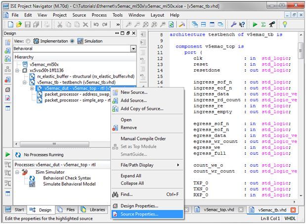
1. Switch to the Simulation View in Project Navigator. Right-click on the v5emac_dut –
v5emac_top instance from the Pane of the Design panel and click Source Properties.
2. Select the Hardware Co-Simulation category. Check the Enable Hardware
Co-Simulation checkbox. Set the Clock Port to clk. Select ML506 (JTAG) as the
Target Board for Hardware Co-Simulation.
Processing Live Ethernet Traffic
UG819 (v 13.2) July 28, 2011 www.xilinx.com 37Chapter 2: Tutorial
Note The instance enabled for hardware co-simulation is now marked with a
special icon .
If the instance selected for hardware co-simulation does not change in subsequent
runs, you can turn on the Enable Incremental Implementation option to skip the
synthesis, implementation, and bitstream generation for hardware co-simulation.
It allows the test bench or any portion simulated in software to be modified and
simulated again quickly.
3. Select the v5emac_tb instance from the Pane of the Design panel. Go to the Pane
of the Design panel, right-click on Simulate Behavioral Model, and click Process
Properties.
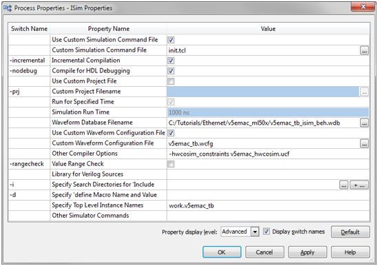
4. Change the Property display level to Advanced. Set the following properties for the
Simulate Behavioral Model process:
• Check Use Custom Simulation Command File.
Processing Live Ethernet Traffic
38 www.xilinx.com UG819 (v 13.2) July 28, 2011Chapter 2: Tutorial
• Set Custom Simulation Command File to init.tcl.
• To set this option, the Use Custom Waveform Configuration File needs to be
checked.
• Set Other Compiler Options to -hwcosim_constraints v5emac_hwcosim.ucf.
The init.tcl script is executed when the ISim simulation starts. It runs the simulation
for 50 ns to perform an initial reset of the design.
The v5emac_tb.wcfg file provides a customized waveform configuration view for
this tutorial.
Note The custom constraints file for hardware co-simulation is provided to the ISim
compiler through the —hwcosim_constraints switch. This property is currently not
accessible in the Project Navigator GUI, so that we specify it through the Other
Compiler Options.
5. Run the Simulate Behavioral Model process for the v5emac_tb instance.
Processing Live Ethernet Traffic
UG819 (v 13.2) July 28, 2011 www.xilinx.com 39Chapter 2: Tutorial
Compiling from the Command Line
The ISim compiler can be invoked through the Fuse command line tool. As in the pure
software simulation flow, you need to provide Fuse a project file, the design top-level
module(s), and other optional arguments such as libraries to link in and library search
paths. To compile the design for hardware co-simulation, you need to provide the extra
arguments listed below:
fuse -prj
-hwcosim_instance
-hwcosim_clock
-hwcosim_board
-hwcosim_constraints
-hwcosim_incremental
• hwcosim_instance specifies the full hierarchical path of the instance to co-simulate
in hardware.
• hwcosim_clock specifies the port name of the clock input for the instance.
– This is the clock in the lock-step portion, which is to be controlled by the test
bench.
– For a design with multiple clocks, specify the fastest clock using this option so
that ISim can optimize the simulation. Other clock ports are treated as regular
data ports.
• hwcosim_board specifies the identifier of the hardware board to use for
co-simulation. A few Virtex-5 boards are supported by default:
– ml501-jtag: Xilinx ML501 Evaluation Platform
– ml505-jtag: Xilinx ML505 Evaluation Platform
– ml506-jtag: Xilinx ML506 Evaluation Platform
– ml507-jtag: Xilinx ML507 Evaluation Platform
– ml510-jtag: Xilinx ML510 Evaluation Platform
– xupv5-jtag: Xilinx XUPV5-LX110T Evaluation Platform
• hwcosim_constraints (optional) specifies the custom constraints file that provides
additional constraints for implementing the instance for hardware co-simulation.
We also use the constraints file to specify which ports of the instance are mapped to
external I/Os or clocks.
• hwcosim_incremental (optional) specifies whether Fuse should reuse the last
generated hardware co-simulation bitstream and skip the implementation flow.
For example, to compile the EMAC design for this tutorial, you can run the Fuse
command line as follows:
fuse -prj v5emac_tb.prj v5emac_tb
–o v5emac_tb.exe
-hwcosim_instance /v5emac_tb/v5emac_dut
-hwcosim_clock clk
-hwcosim_board ml506-jtag
-hwcosim_constraints v5emac_hwcosim.ucf
Step 5: Running ISim Hardware Co-Simulation
The simulation executable generated by the ISim compiler runs in the same way in
both the pure software simulation and hardware co-simulation flow. Project Navigator
automatically launches the simulation executable in GUI mode after the compilation
finishes.
Processing Live Ethernet Traffic
40 www.xilinx.com UG819 (v 13.2) July 28, 2011Chapter 2: Tutorial
In the Instances and Processes view, a special icon indicates that an instance is
selected for hardware co-simulation. As the instance runs in hardware, you cannot
expand it to see its internal signals and submodules.
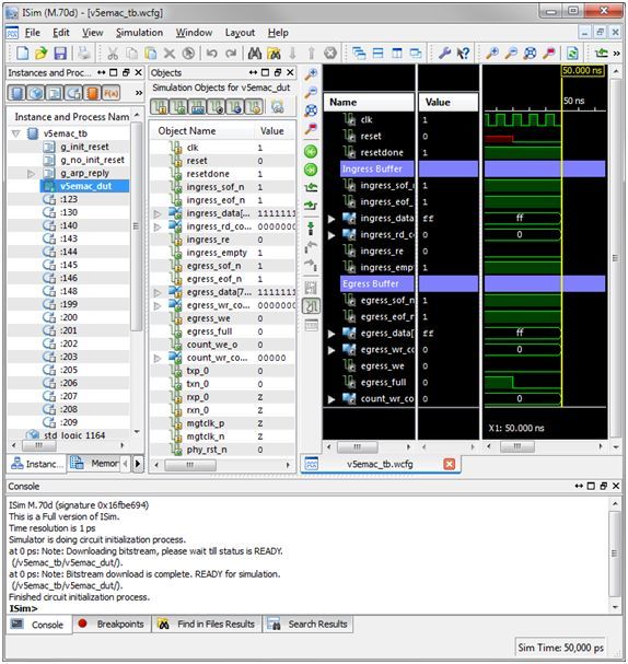
Before the simulation starts, ISim programs the FPGA with the bitstream file generated
for hardware co-simulation. You may notice the message in the ISim console window:
Downloading bitstream, please wait till status is READY. After the
FPGA is configured, the console shows Bitstream download is complete.
READY for simulation. From this point, you can run the simulation and interact
with the ISim interface the same way you do in the software simulation flow.
The test bench initially resets the system by asserting the reset signal. The resetdone
signal transits from low to high quickly after the reset is de-asserted. This is because the
reset process takes place in hardware at full speed. It may take a much longer time if
the same process is simulated in software.
Processing Live Ethernet Traffic
UG819 (v 13.2) July 28, 2011 www.xilinx.com 41Chapter 2: Tutorial
If the Ethernet MAC receives packets, the packets are forwarded from RX LocalLink
FIFO to ingress FIFO. When the test bench runs for a few thousand nanoseconds, it
starts to read packets out from the ingress FIFO. The ISim console prints out a message
like receive a packet at 110 ns when there is a packet read from the ingress
FIFO. You can also observe the packet data (ingress_data) from the ISim waveform.
If you run the ISim simulation continuously (using the Run All command), you
can observe the packet stream and how the packet processor processes the packets.
As a validity check, you can install a third-party packet sniffer such as Wireshark
(http://www.wireshark.org) to compare the packets captured by the ISim test bench, and
the ones captured by the sniffer.
Processing Live Ethernet Traffic
42 www.xilinx.com UG819 (v 13.2) July 28, 2011Chapter 2: Tutorial
Now you can modify your packet processor in your test bench and quickly
recompile the ISim test bench with the Enable Incremental Implementation turned
on in the Hardware Co-Simulation properties. This substantially speeds up the
develop-compile-debug cycle for your HDL design.
Processing Live Ethernet Traffic
UG819 (v 13.2) July 28, 2011 www.xilinx.com 43Processing Live Ethernet Traffic 44 www.xilinx.com UG819 (v 13.2) July 28, 2011
Appendix

Additional Resources
                         •   Xilinx Glossary -
                             http://www.xilinx.com/support/documentation/sw_manuals/glossary.pdf
                         •   Xilinx Documentation - http://www.xilinx.com/support/documentation
                         •   Xilinx Support - http://www.xilinx.com/support

Processing Live Ethernet Traffic
UG819 (v 13.2) July 28, 2011                   www.xilinx.com                                      45
You can also read