MILL QUICK START GUIDE - RHINOCAM 2021 - MECSOFT CORPORATION
←
→
Page content transcription
If your browser does not render page correctly, please read the page content below
MILL
Quick Start Guide
     RhinoCAM 2021
           Published: January 2021

                                     MecSoft Corpotation
                                       © Copyright 1998-2021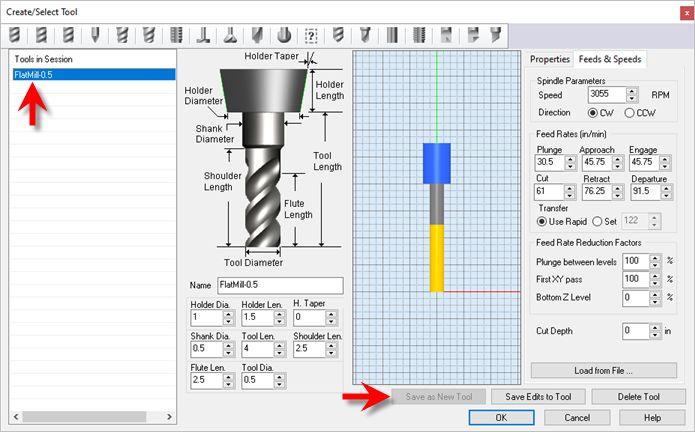
RhinoCAM-MILL 2021 Quick Start Guide
                          by MecSoft Corporation

User Notes:
________________________________
________________________________
________________________________
________________________________
________________________________
________________________________
________________________________
________________________________
________________________________
________________________________
________________________________
________________________________
________________________________
________________________________
________________________________
________________________________
________________________________
________________________________
________________________________
________________________________
Contents                3

Table of Contents

Quick Start                                                                                                                                           5

Resource Guide                                                                                                                                        8

About this Guide                                                                                                                                      9
            1 Useful ...................................................................................................................................
                      Tips                                                                                                                               9
            2 About...................................................................................................................................
                     the MILL Module                                                                                                                   10
            3 Using...................................................................................................................................
                     this Guide                                                                                                                        10
            4 Watch
                  ...................................................................................................................................
                     the Video                                                                                                                        11

Getting Ready                                                                                                                                        12
            1 Running
                  ...................................................................................................................................
                        RhinoCAM                                                                                                                      12
            2 About...................................................................................................................................
                     the RhinoCAM Display                                                                                                              12
            3 Load ...................................................................................................................................
                    the MILL Module                                                                                                                    13
            4 Load ...................................................................................................................................
                    the Part Model                                                                                                                     16
            5 Machining
                  ...................................................................................................................................
                           Strategy                                                                                                                   18
            6 Main ...................................................................................................................................
                    Programming Steps                                                                                                                  18
            7 Define
                   ...................................................................................................................................
                      the Machine Tool                                                                                                                 19
            8 Select
                   ...................................................................................................................................
                      the Post Processor                                                                                                               20

The Setup                                                                                                                                            23
            1 Machining
                  ...................................................................................................................................
                           Setup - Skip if in STD or EXP Configuration                                                                                23
            2 Create
                   ...................................................................................................................................
                      Stock Geometry                                                                                                                   23
            3 Align...................................................................................................................................
                    Part and Stock                                                                                                                     26
            4 About...................................................................................................................................
                     Fixtures - Skip if XPR Configuration                                                                                              28
            5 Specify
                  ...................................................................................................................................
                       Material                                                                                                                       29
            6 Set Work
                   ...................................................................................................................................
                          Coord Sys (Work Zero)                                                                                                        31

Create Tools                                                                                                                                         37

Machine the Inner Profiles                                                                                                                           43
            1 Control
                   ...................................................................................................................................
                       Geometry                                                                                                                        44
            2 Cutting
                    ...................................................................................................................................
                        Tool                                                                                                                            46
            3 Feeds...................................................................................................................................
                     and Speeds                                                                                                                        47
            4 Clearance
                   ...................................................................................................................................
                            Parameters                                                                                                                 48
            5 Cut Parameters
                   ................................................................................................................................... 50
            6 Cut Level
                   ...................................................................................................................................
                           Parameters                                                                                                                  52

© MecSoft Corporation

                                                                                                                                                             3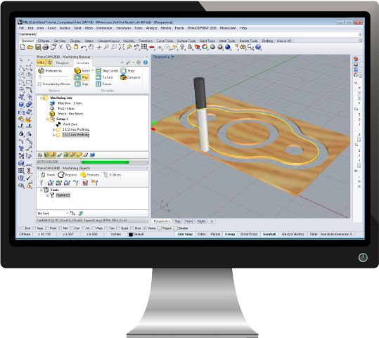
4     RhinoCAM-MILL 2021 Quick Start Guide

       7 Entry/Exit
              ...................................................................................................................................
                      Parameters                                                                                                                  52
       8 Cut Material
              ...................................................................................................................................
                          Simulation                                                                                                              54

Machine the Outer Profile                                                                                                                     59

Post G-Code                                                                                                                                   65

Generate Reports                                                                                                                              68
       1 Information
              ...................................................................................................................................
                         Report                                                                                                                   68
       2 Shop...................................................................................................................................
              Documentation                                                                                                                      69

Where to go for more help                                                                                                                     72

          Index                                                                                                                               73

                                                                                                                         © MecSoft Corporation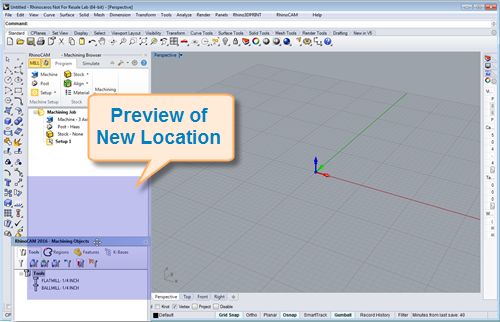
Quick Start        5

Quick Start

                                          RHINOCAM2021

                                  Prefer Printed Documentation? Check Here!
          Quick Start Guides for each RhinoCAM module are available in both PDF and Video format. Refer
          to the following information to access these resources:

                        What's New!
                        You can find out What's New in the latest release of RhinoCAM here:
                        What's New in RhinoCAM 2021
                        Watch the What's New in 2021 Webinar! (Coming Soon!)

                        The Complete Quick Start Video Play List
                        Here is a link to the complete 2021 Video Play List

                        How to Access the Quick Start Guide Documents
                        To help you quickly get started in working with each module, select one of the Help
                        buttons located on the RhinoCAM Learning Resources dialog.
                        You will find:
                        · Quick Start Guides
                        · What's New documents
                        · Online Help links
                        The Quick Start Guides will help you step through an example tutorial which will
                        illustrate how to use the module. To access the Learning Resources dialog:
                        1. From the Rhino Main Menu, drop down the Main menu and select Learn ...

© MecSoft Corporation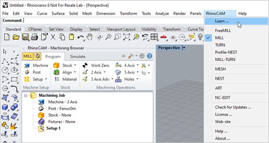
6   RhinoCAM-MILL 2021 Quick Start Guide

                                      To access the Learning Resources dilog in RhinoCAM

         2. Select a document from the Learning Resources dialog to get started using the
            module of your choice.

                You can also select the Open Quick Start Files Folder button located at the bottom
            of the dialog to open the Quick Start folder where the source files (start and
            completed versions) are located.

                                                                                           © MecSoft Corporation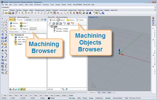
Quick Start   7

                        Learning Resources Dialog

© MecSoft Corporation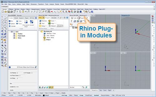
8      RhinoCAM-MILL 2021 Quick Start Guide

Resource Guide
      Download this PDF Guide for a list of the available RhinoCAM Resources.

              2021 RhinoCAM Resource Guide

                                       The 2021 RhinoCAM Resource Guide!
                                       18 Pages
                                       Lists PDF downloads and Online resources including Quick Start
                                       Guides, Reference Guides, Exercise Guides, Tutorials and
                                       More.

                                       Click Here to download this Free guide!

                                                                                    © MecSoft Corporation
About this Guide 9
About this Guide
RHINOCAM2021
On-line help compiled on: Friday, January 22, 2021
3.1 Useful Tips
Here are some useful tips that will help you use this guide effectively.
1. For purposes of brevity, Rhino refers to both Rhinoceros 6 or Rhino 7.
2. Copy the tutorial files to a location other than the installation folder to make sure you
have read/write privileges to the files.
3. Once you start working with the tutorial file, save your work periodically!
4. Don’t stress out too much if you are having trouble with the tutorial. Call us or send us
email and we can help you out.
5. Most of all have fun!
© MecSoft Corporation10 RhinoCAM-MILL 2021 Quick Start Guide
3.2 About the MILL Module
The RhinoCAM MILL module offers fast gouge free solids/surface model machining technology
coupled with cutting simulation/verification capabilities running inside Rhino (6 or 7) for
programming CNC Mills. This integration allows for seamless generation of toolpath and cut
material simulation/verification within Rhino, for programming milling machines that support 3, 4
and 5 axis continuous machining.
The module also comes with numerous post-processors to output the programmed G-code to
some of the most popular machines on the market. A simple and well thought out user interface
makes this system one of the most intuitive and easy to use milling systems available today.
You can work with the native Rhino (5 or 6) data as well as use any of the data types that can be
imported into Rhino such as solids, surfaces and meshes. Then you can use the RhinoCAM MILL
module with its wide selection of tools and toolpath strategies to create machining operations
and associated toolpaths for CNC Mills. These toolpaths can then be simulated and verified, and
finally post-processed to the controller of your choice.
3.3 Using this Guide
If you have installed RhinoCAM successfully on your computer and are now looking at the blank
screen of Rhino and wondering what to do next, this is the guide for you. This guide will explain
how to get started in using the RhinoCAM MILL module to program a simple part through an
example.
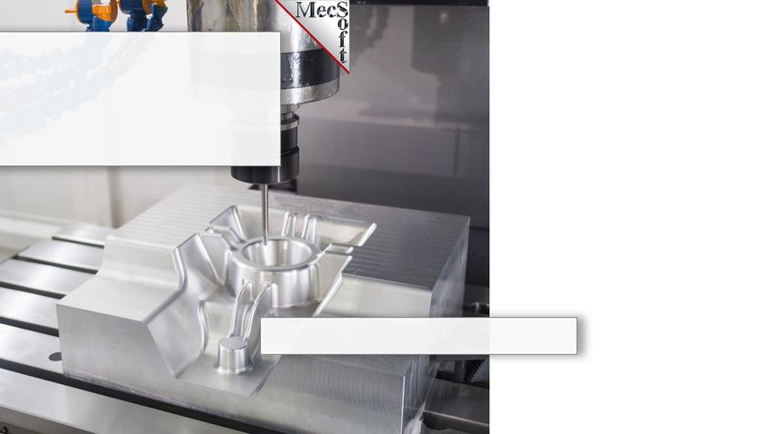
This guide will illustrate machining of a simple prismatic part such as this gasket using 2-1/2 Axis
milling operations. Even though we have created a 3D representation of the gasket, it will become
apparent as we go that we can machine this using just 2D curves. The reason we are able to do
this is because of the prismatic nature of this model, which means that the curves can be treated
as the edges of vertical walls in the geometry.
This guide has two associated Rhino files that you can find located in the QuickStart folder under
the installation folder of RhinoCAM. The first file is a completed file that contains all of the
completed toolpaths and machining operations and represents the file that you should end up
with after working through the tutorial. The other file is a starter file that contains only the
geometry. Use the completed file as a reference. Copy the starter file and use this file to begin
the tutorial.
© MecSoft CorporationAbout this Guide 11
MILLQuickStartTutorial.3dm
3.4 Watch the Video
Want to see a video demonstration of this quick start guide? Just click on the image below.
RhinoCAM Milling Quick Start Guide
© MecSoft Corporation12 RhinoCAM-MILL 2021 Quick Start Guide
Getting Ready
4.1 Running RhinoCAM
Locate the Rhinoceros 6 (or Rhinoceros 7) shortcut on your desktop and double click to launch the
application.
Alternatively you can also click on the Windows Start button and select All Programs. Go to the
program group containing Rhinoceros 6 (or Rhinoceros 7). (The name of this program group will
usually be called Rhinoceros, unless you specified otherwise during setup.)
Once you locate the program group, select it and then select Rhinoceros to launch the application.
If the installation was successful, upon launching of Rhino you should observe a menu entry called
RhinoCAM 2021 in the main menu bar of Rhino.
If you do not see this menu entry then please check the On Line Help document of the product
(found in the installation folder) for help with trouble shooting the installation.
4.2 About the RhinoCAM Display
Before we begin, let's talk a bit about the RhinoCAM display. When you run RhinoCAM for the
very first time, your screen may look this.
These windows on the left belong to plug-in modules that are currently loaded. For now, let's
close all of them.
© MecSoft CorporationGetting Ready 13
With all plug-in modules closed your screen will look like this:
4.3 Load the MILL Module
Now, let's begin by launching the RhinoCAM MILL module.
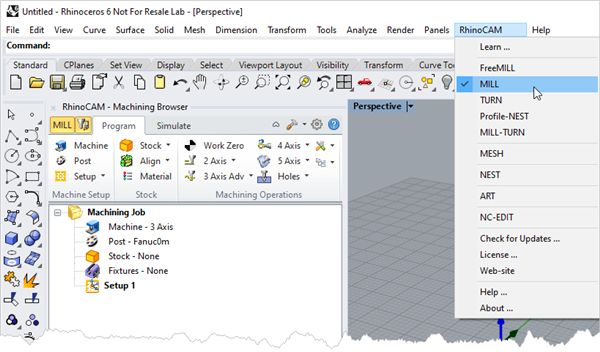
1. From the Rhino main menu bar, you will see the RhinoCAM menu item.
2. Drop-down the menu and pick MILL to load the module.
© MecSoft Corporation14 RhinoCAM-MILL 2021 Quick Start Guide
3. Docked on the left you will see the Machining Browser and the Machining Objects
Browser. When you first run RhinoCAM, these two browsers my be docked side by side.
However, you can move them anywhere on the screen that feels comfortable for you.
4. For example, let's move the Machining Objects Browser so that it displays under the
Machining Browser on the left. Simply left-click and hold the title bar of the browser and
drag it around on your screen.
© MecSoft CorporationGetting Ready 15
While do so you will see possible docking location highlight on the display.
5. We'll drag the Machining Objects Browser over the base of the Machining Browser until
the cursor activates the the bottom docking location as shown below.
When the preview of the new location displays, let go of the right-mouse button and the
browser will move to that location.
6. You can also re-size the height and width of each browser making sure that all of the
command icons and menus are easily accessible.
© MecSoft Corporation16 RhinoCAM-MILL 2021 Quick Start Guide
4.4 Load the Part Model
“Part” refers to the geometry that represents the final manufactured product. You can create parts
within Rhinoceros or import geometry created in another CAD system.
1. Select File / Open from the Main Menu bar, or click the Open icon from the Standard bar.
2. From the Open dialog box, select the MILLQuickStartTutorial.3dm file from the C:
\ProgramData\MecSoft Corporation\RhinoCAM 2021 for Rhino x.x\QuickStart\ folder. As
mentioned before, it is advisable to make a copy of this part at a suitable alternative
folder so that you have write privileges to modify the part.
© MecSoft CorporationGetting Ready 17
By default, the ProgramData folder is "hidden" from view. Here are the steps
to Show hidden files and folders:
1. For Windows 8 users: Go to Control Panel > Appearance and Personalization >
Folder Options.
For Windows10 users: Go to Control Panel > Appearance and Personalization >
File Explorer Options.
2. Select View tab and under advanced settings select Show Hidden files and
folders, clear the check boxes for:
· Hide extensions for known file types
· Hide protected operating system files (Recommended)
3. Click Apply and OK.
When the Load Settings from File dialog appears, pick No for this file. In the future you
may have older files whose CAM System Preferences you wish to use so leave the box Do
not display dialog again unchecked for now.
The part appears as shown below
© MecSoft Corporation18 RhinoCAM-MILL 2021 Quick Start Guide
MILLQuickStartTutorial.3dm
You can import 2D drawings, Solid, Surface and Mesh models that are
supported in Rhinoceros.
3. From the Rhino display, double-left-click on the Perspective View tab to maximize it.
4.5 Machining Strategy
Based on the type of geometry of this part, we will machine this model out of a 10 x 6 x 1/8 inch
poplar wood sheet. Since the part is relatively thin and prismatic, we will machine this out by
using only a single type of machining operation - 2-½ axis machining method called Profiling. We
will also use just a single 0.5 inch flat end mill for performing all machining. We will also assume
that the wooden sheet will be held to the machine table or the spoil sheet on the table using
double-sided tape or a vacuum table requiring no clamps or fixtures.
4.6 Main Programming Steps
The following steps will be followed in machining this model. Some of these steps will have to be
performed just once and others may have to be repeated to complete the machining.
1. Define the Machine and Post-processor to use.
2. Define the Machining Setup including Stock Geometry, Material and Work Zero.
3. Create and Select a Tool to use for machining.
© MecSoft CorporationGetting Ready 19
4. Create the Machining Operations including the Feeds and Speeds, the Clearance Plane
and other Cutting Parameters.
5. Generate the toolpaths.
6. Simulate the toolpaths.
7. Post Process the toolpaths.
8. Generate Shop Documentation.
4.7 Define the Machine Tool
Let's start by defining the Machine to use for this job.
1. From the Program tab select Machine to display the dialog box.
2. Under Machine Type, set the Number of Axes to 3 Axis.
3. Pick OK and notice that the Machine type now appears under Machining Job in the
Machining Browser.
© MecSoft Corporation20 RhinoCAM-MILL 2021 Quick Start Guide
4.8 Select the Post Processor
Next, we'll define the Post Processor.
1. From the Program tab select Post to display the dialog.
2. For the Current Post Processor, select Haas from the list of available posts.
3. Then set the Posted File Extension to .nc. Other file extensions are available depending
on your machine requirements.
© MecSoft CorporationGetting Ready 21
By default, post processor files are located under
C:\ProgramData\MecSoft Corporation\RhinoCAM 2021 for Rhino
x.x\Posts\MILL\
The program to send the posted output data to is set to notepad.
4. Pick OK and notice that the Post type now appears under Machining Job in the Machining
Browser.
© MecSoft Corporation22 RhinoCAM-MILL 2021 Quick Start Guide
© MecSoft CorporationThe Setup 23
The Setup
5.1 Machining Setup - Skip if in STD or EXP Configuration
Now let's define the Machining Setup. The Machining Setup allows you to orient the Machine
Coordinate System such that the part is aligned in exactly same way as it would be fixtured on the
machine tool for cutting.
This functionality is available only in the Professional and
Premium configurations of the product. When working with
your part files and running the Express, Standard or Expert
configuration, you will have to use the CAD tools to orient the part
geometry so that it is in the correct orientation for machining.
If in the future, if there is no Setup1 listed under your Machining Job, the system automatically
creates one when a Work Zero or an operation is generated.
However in our tutorial part, by default, the MCS (Machine Coordinate System) is already aligned
with the WCS (World Coordinate System) so this step is not required for this part.
However, in production you can have multiple setups and assign different machining orientations
for each, when running the Professional or Premium configurations.
5.2 Create Stock Geometry
In this step we'll define the raw stock from which to cut the part.
1. From the Program tab select Stock and then select Box Stock from the menu to display the
dialog.
© MecSoft Corporation24 RhinoCAM-MILL 2021 Quick Start Guide
2. Under Dimensions, set the Length L to 10.0, Width W to 6.0 and Height H to 0.125.
Note that the stock dimensions you enter are measured from the corner of the bounding
box selected in this dialog.
© MecSoft CorporationThe Setup 25
The dimensions of the stock are interpreted in relation to the
corner selected in the dialog box above. For example if the corner
of the box is selected as the Bottom South West corner (as shown in
the dialog above), the Length (L) is interpreted to be along the +X axis,
the Width (W) along the +Y axis and the Height (H) along the +Z axis.
The direction of the dimensions will change depending on the corner
selected. For example if the Top South West corner is selected, then
the Height (H) is interpreted to be along the –Z axis and so the stock
will extend below the corner.
3. Pick OK and notice that the Stock type now appears under Machining Job in the Machining
Browser.
© MecSoft Corporation26 RhinoCAM-MILL 2021 Quick Start Guide
4. If the stock does not display on the screen, select the Stock Visibility icon located at the
base of the Machining Browser.
5.3 Align Part and Stock
Once the stock model is created you can move it in alignment with the part if needed.
1. From the Program tab select Align and then Align Stock from the menu to display the
dialog. Notice that we are working our way from left to right in the Program tab.
© MecSoft CorporationThe Setup 27
2. For Z Alignment select Top and for XY Alignment select Center and then pick OK.
© MecSoft Corporation28 RhinoCAM-MILL 2021 Quick Start Guide
The stock is now aligned to the Center of the part in XY and the Top of the part in Z.
5.4 About Fixtures - Skip if XPR Configuration
If you are running the STD or higher configuration, you will notice an icon in your Machining Job
named Fixture. For this exercise we are assuming that our stock is fastened to the machining
table using vacuum or double-sided tape. In the future you can model your fixtures and define
them using the steps below.
1. Find the Fixture icon located under the Machining Job tree and double-left-click on it.
Double-left-click on the Fixture icon to
define a fixture
2. You are prompted to select one or more solids to represent your fixture(s). Right-click or
press when done. The Create Machining Fixture dialog will display listing your
selected geometry.
© MecSoft CorporationThe Setup 29
Create Machining Fixture Dialog
3. Since we are not using fixtures for this exercise, select the Cancel button to continue.
5.5 Specify Material
Next, we'll set the material for the stock geometry.
1. From the Program tab select Material to display the dialog box.
© MecSoft Corporation30 RhinoCAM-MILL 2021 Quick Start Guide
2. For Material, select Wood from the list of available materials and then pick OK.
3. If the material texture does not display on the stock, select the Material Texture Visibility
icon located at the base of the Machining Browser.
© MecSoft CorporationThe Setup 31
5.6 Set Work Coord Sys (Work Zero)
Now that the stock is aligned to the part geometry, in this step, we will establish the work
coordinate origin also referred to as the Work Zero. The Work Zero translates the MCS origin from
the Setup to the desired location. This can be set to any location on the part or stock geometry.
The Work Zero defines the zero point with respect to which all
toolpath points are interpreted by the controller. This would
normally be the same as the tool touch off point on the actual
work-piece on your machine. So care should be taken to make sure
that this Work Zero point defined in RhinoCAM matches the tool
zero point used on the actual work piece located on the table of
your machine.
1. From the Program Tab select Align and then Set World CS.
© MecSoft Corporation32 RhinoCAM-MILL 2021 Quick Start Guide
2. Then select Set to Stock Box.
3. Then set Zero Face to Highest Z and Zero Position to South West corner. This sets the
machine home to the top of the stock material and the southwest corner of the stock
geometry.
4. Pick OK and the part and stock geometry are now transformed to the World Coordinate
Origin (WCS).
© MecSoft CorporationThe Setup 33
Alternatively you can use Work Zero to set the work coordinate origin. Instead of moving the part
and stock to the WCS origin, this moves the machine coordinate system origin to the specified
location.
1. From the Program Tab select Work Zero to display the dialog.
© MecSoft Corporation34 RhinoCAM-MILL 2021 Quick Start Guide
5. Then select Set to Stock Box.
6. Then set Zero Face to Highest Z and Zero Position to South West corner. This sets the
machine home to the top of the stock material and the southwest corner of the stock
geometry.
© MecSoft CorporationThe Setup 35
7. Pick Generate and notice that the MCS is translated and that the Work Zero now appears
under Setup 1 in the Machining Browser.
© MecSoft Corporation36 RhinoCAM-MILL 2021 Quick Start Guide
Note that the Work Zero should appear as the FIRST item UNDER
the Setup in the Machining Job tree so that all operations in that
Setup will inherit that Work Zero origin.
© MecSoft CorporationCreate Tools 37
Create Tools
To machine the above part we will now create a ½ inch (0.5”) Flat End Mill.
1. Next to the Program tab at the top of the Machining Browser, locate and select the Tools
Machining Objects button. Selecting this button toggles the Machining Objects lower
portion of the browser On and Off. Then locate the Tools tab and pick the Create/Edit
Tools icon.
These buttons and icons are shown in the menus below:
First pick the Tools Machining Objects button to make sure the Tools tab is displayed:
Then select the Create/Edit Tools icon:
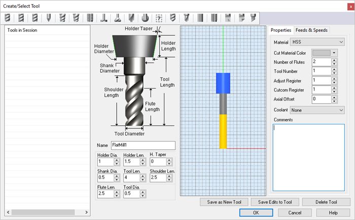
2. This will display the Create/Select Tool dialog. Select Flat Mill from the Tool Type menu at
the top of the dialog.
© MecSoft Corporation38 RhinoCAM-MILL 2021 Quick Start Guide
3. Set tool Name to FlatMill-0.5 and Tool Diameter to 0.5. Under the Properties tab set
Material to HSS and Tool Number to 1.
4. Switch to Feeds and Speeds tab and click Load from File.
© MecSoft CorporationCreate Tools 39
5. From the dialog that displays, set Stock Material to Wood and Tool Material to HSS. Check
the other parameters in this dialog and adjust as required for your machine tool.
© MecSoft Corporation40 RhinoCAM-MILL 2021 Quick Start Guide
6. Now pick OK and the computed cut feedrate and spindle speed are transferred to the
Feeds and Speeds tab of the Create/Select Tool dialog.
© MecSoft CorporationCreate Tools 41
7. Pick Save as New Tool to save the tool. The tool is now created and listed under Tools in
Session on the left side of the dialog.
8. Pick OK to close the dialog.
You can edit the tool properties and pick Save Edits to Tool to
save the changes to this tool. To edit and save this as a New
Tool, you must enter a different tool Name.
The created tool is now listed under the Tools tab in Machining Objects browser.
In the future you can save your tools to a Tool Library. To save
Tools to a library, click Save Tool Library under the Tools tab in
© MecSoft Corporation42 RhinoCAM-MILL 2021 Quick Start Guide
the Machining Objects Browser and specify a folder location and file
name in the Save as dialog box. Two Tool Library file formats are
supported (*.vkb and *.csv). The native Tool Library file format for
RhinoCAM is *.vkb.
© MecSoft CorporationMachine the Inner Profiles 43
Machine the Inner Profiles
Now we're ready to create our first machining operation.
1. From the Program tab select 2 Axis and then Profiling from the menu of 2 Axis operations.
2½ Axis Profiling Menu Item
This will display the 2½ Axis Profiling operations dialog. We will go over the steps for
creating the profile operation for the inner features of the Gasket.
© MecSoft Corporation44 RhinoCAM-MILL 2021 Quick Start Guide
7.1 Control Geometry
2. Under the Control Geometry tab pick Select Curve/Edge Regions.
The Profiling operation dialog is now minimized and allows selection of features to
machine. We will now select the surface edges of the 3 inside hole features.
3. Select the first hole by clicking near the upper surface edge as shown below.
© MecSoft CorporationMachine the Inner Profiles 45
4. Repeat to select the edges of the two smaller holes.
Press or right-click to end the selection.
5. The 2½ Axis Profiling dialog comes back up displaying the selected Part Regions. They are
also highlighted on the part.
6. Notice that selecting a Part Region from the list highlights the corresponding surface edge
curve on the part.
© MecSoft Corporation46 RhinoCAM-MILL 2021 Quick Start Guide
7.2 Cutting Tool
Now we'll select the Tool for our operation:
1. Switch to the Tool tab of the dialog.
2. Select Flat Mill-0.5 under Tools. The 0.5" Flat End Mill is now selected as the active tool.
© MecSoft CorporationMachine the Inner Profiles 47
Note that the Tool parameters of the currently active tool are always displayed in the
status bar at the bottom of the Machining Objects Browser.
7.3 Feeds and Speeds
Now we'll set the Speeds and Feeds for our operation:
1. Switch to the Feeds & Speeds tab of the dialog.
2. Select the Load from Tool button. RhinoCAM will retrieve the feeds and speeds
parameters that were set when the tool was defined and associate them with the current
operation.
© MecSoft Corporation48 RhinoCAM-MILL 2021 Quick Start Guide
7.4 Clearance Parameters
Now we'll set the Clearance parameters for our operation:
1. We'll switch to the Clearance Plane tab of the dialog.
2. Set the Clearance Plane Definition to Automatic and Cut Transfer Method to Clearance
Plane.
© MecSoft CorporationMachine the Inner Profiles 49
In the Automatic mode, RhinoCAM will determine a safe Z height for locating the
clearance plane. Setting the Cut Transfer Method to Clearance Plane will force all transfer
moves to be performed in this determined clearance plane.
When this tab of the dialog is active, the clearance plane is shown on the graphics screen.
© MecSoft Corporation50 RhinoCAM-MILL 2021 Quick Start Guide
7.5 Cut Parameters
Now we'll set the Cut Parameters for our operation:
1. Switch to the Cut Parameters tab of the dialog.
2. Set the Stock to 0. This means that we will not be leaving any thickness on the part after
machining.
3. Under Cut Start Point, uncheck Use Mid-Point of longest side.
4. Under the Cut Start Side section check the box next to Use Outside/Inside for Closed
Curves and then select Inside.
© MecSoft CorporationMachine the Inner Profiles 51
Alternately you could use the Determine using 3D Model option. In this case RhinoCAM
would use the 3D model to determine which side of the curve to place the cutter for
machining.
© MecSoft Corporation52 RhinoCAM-MILL 2021 Quick Start Guide
7.6 Cut Level Parameters
Now we'll set the Cut Level parameters for our operation:
1. Select the Cut Levels tab of the dialog.
2. Set Location of Cut Geometry to At Top.
3. For Total Cut Depth, enter 0.125. The cut depth is always set as an absolute value.
4. This automatically sets the Rough Depth and Rough Depth/Cut to 0.125.
7.7 Entry/Exit Parameters
Next we'll set Entry and Exit parameters for our operation:
1. Select the Entry/Exit tab of the dialog.
© MecSoft CorporationMachine the Inner Profiles 53
2. Entry/Exit parameters control how the cutter will engage material as it begins cutting and
how it leaves the material as it completes cutting.
3. Set Entry Motions and Exit Motions to None.
4. Now pick Generate.
© MecSoft Corporation54 RhinoCAM-MILL 2021 Quick Start Guide
5. The 2½ Axis Profile toolpath is generated and the operation is listed under Setup 1 in the
Machining Browser. NOTE: Notice that it appears UNDER the Work Zero in the Setup.
6. The toolpath is also displayed in the graphics screen.
7. Note that the display of the toolpath in the graphics screen can be turned on/off by
selecting the Toggle Toolpath Visibility icon located at the base of the Machining
Browser.
7.8 Cut Material Simulation
The new toolpath can now be Simulated to display the in-process stock model.
1. Switch to the Simulate tab at the top of the Machining Browser.
2. Select Preferences from the Simulate tab.
© MecSoft CorporationMachine the Inner Profiles 55
3. From the Preferences dialog set the following:
Simulation Model: Polygonal Model
Simulation Accuracy: Fine
Remove Remnants During Simulation: Unchecked
© MecSoft Corporation56 RhinoCAM-MILL 2021 Quick Start Guide
CAM Preferences > Simulation
4. Now pick OK to close the Simulation Preferences dialog.
5. Pick OK from the message dialog.
© MecSoft CorporationMachine the Inner Profiles 57
6. Then from the Simulate tab, uncheck Simulate by Moves and adjust the slider to the left to
slow down the simulation speed.
7. Now, under Setup 1 in the Machining Job tree, select the 2½ Axis Profiling operation we
just created and then pick Play to start the simulation.
8. You can stop the simulation at anytime by selecting the Pause button from the Simulate
tab. Subsequent to pausing the simulation, you can either choose to continue the
simulation by selecting the Play button again or exit the simulation by selecting the Stop
button.
© MecSoft Corporation58 RhinoCAM-MILL 2021 Quick Start Guide
9. To view the cut model with textures applied, select the Toggle Material Texture Visibility
icon located at the base of the Machining Browser.
© MecSoft CorporationMachine the Outer Profile 59
Machine the Outer Profile
Now we will turn our attention to machining the outer profile of the part. Again, we will create a
simple profile toolpath, this time around the outer perimeter of the part.
1. Switch to Program tab in the Machining Browser.
2. Select the 2½ Axis Profiling operation we just created.
3. Right-click on the selected operation and select Copy.
4. Now Right-click again and select Paste.
© MecSoft Corporation60 RhinoCAM-MILL 2021 Quick Start Guide
5. This creates a copy of the operation and places it below the original in the Machining Job.
© MecSoft CorporationMachine the Outer Profile 61
6. Now right-click on the second operation and pick Edit to adjust its parameters.
7. From the Control Geometry tab, pick Remove All.
8. From the Control Geometry tab, pick Select Curve/Edge Regions.
9. Select the top outer surface edge and then right-click or press enter to complete the
selection.
© MecSoft Corporation62 RhinoCAM-MILL 2021 Quick Start Guide
10. Switch to the Cut Parameters tab and change the Cut Start Side to Outside.
© MecSoft CorporationMachine the Outer Profile 63
11. We'll accept all of the remaining parameters and pick Generate.
12. The new 2½ Axis Profiling toolpath is generated and displayed on the graphics screen.
© MecSoft Corporation64 RhinoCAM-MILL 2021 Quick Start Guide
13. Now we'll select the new 2½ Axis Profiling operation we just created, select the
Simulation tab and then pick Play.
© MecSoft CorporationPost G-Code 65
Post G-Code
Now with the toolpaths complete we're ready to post-process to an output text file containing G-
codes that can then be sent to the machine tool to actually machine the part.
1. Select Setup 1 from the Machining Job, right-click and select Post. This will post-process
all operations created under the Setup.
2. The Post & Save As dialog is displayed. By default, the Part file name and the Setup name
are appended for the G-code File name. Also by default, the posted G-code file is Saved
in the folder where the part file is located.
The output file names can be controlled by setting the Posted
File Naming Conventions sections of the Set Post-Processor
Options dialog. Refer to the Select the Post Processor step for
displaying this dialog.
© MecSoft Corporation66 RhinoCAM-MILL 2021 Quick Start Guide
As you may recall we set the post to Haas back in the Select Post
Processor section of this guide. You can change the post
processor from this dialog by selecting a different one from the drop
down menu in the Current Post list. The posted G-code by default
will be saved to the folder where the part file is located.
3. Now pick Post and the G-code file is displayed in Notepad where it can be viewed or
edited manually.
© MecSoft CorporationPost G-Code 67
4. Now close Notepad.
© MecSoft Corporation68 RhinoCAM-MILL 2021 Quick Start Guide
Generate Reports
10.1 Information Report
At any time, you can create a Report of your Machining Operations.
1. Switch to Program tab in the Machining Browser.
2. Select Setup 1.
3. Right-click and select Information to display and Print the report.
This dialog provides an estimate of the machining time required for the operations in the
Setup.
Note (Professional & Premium configurations only): In the future, if your Machining Job
contains multiple Setups, you can perform the same right-click sequence on the
Machining Job to determine the estimated machining time for all Setups.
© MecSoft CorporationGenerate Reports 69
4. Now pick OK to close the Information dialog.
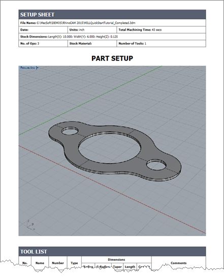
10.2 Shop Documentation
You can also create a Setup Sheet by generating a Shop Document. This is typically used to instruct
machine operators on how to setup and machine the part on the CNC machine.
1. Under the Machining Job, select Setup1.
2. Right-click and select Shop Documentation.
3. From the Save Shop Documentation File dialog, select Template1 and pick Save.
© MecSoft Corporation70 RhinoCAM-MILL 2021 Quick Start Guide
4. This creates an HTML based Shop Document that can be viewed in a web browser.
You can select from one of the multiple HTML templates that are shipped with the product
and generate shop documentation. Each template provides varying amounts of
information. Once you have selected the Output Template and pick Save, a shop
documentation html file will be created and saved. This file can then be printed and/or
viewed in your default web browser such as Internet Explorer.
© MecSoft CorporationGenerate Reports 71
5. Note (Professional & Premium configurations only): In the future, if your Machining Job
contains multiple Setups, you can perform the same right-click sequence on the
Machining Job to generate Shop Documentation for all Setups.
© MecSoft Corporation72 RhinoCAM-MILL 2021 Quick Start Guide
Where to go for more help
Download this PDF Guide for a list of the available RhinoCAM Resources.
2021 RhinoCAM Resource Guide
The 2021 RhinoCAM Resource Guide!
18 Pages
Lists PDF downloads and Online resources including Quick Start
Guides, Reference Guides, Exercise Guides, Tutorials and
More.
Click Here to download this Free guide!
© MecSoft CorporationIndex 73
Index -E-
Entry/Exit
-2- 2½ Axis Profiling 52
2½ Axis Profiling 43
Clearance Plane tab 48 -F-
Control Geometry tab 44 Fixtures 28
Copy/Paste 59
Cut Levels tab 52
Cut Parameters 50 -G-
Edit 59
Entry/Exit tab 52 Generating Reports 68
Feeds and Speeds tab 47 Getting Ready
Information Report 68 Load the Part Model 16
Post G-Code 65 Machining Strategy 18
Simulate 54 Main Programming Steps 18
Tool tab 46
-L-
-A- Learning Resources 5
About Load the Part Model 16
the MILL Module 10 Load the RhinoCAM MILL Module 13
the RhinoCAM Display 12
This Guide 9
using this Guide 10
-M-
Align Part and Stock 26 Machine
Define 19
-C- Machining Fixtures 28
Machining Setup - Skip if in STD or EXP Configuration
23
Clearance Plane 48
Machining Strategy 18
Control Geometry 44
Machining the Outer Perimeter 59
Copy/Paste a Toolpath 59
Machining Time 68
Create Machining Operations 43
Main Programming Steps 18
Create Stock Geometry 23
Create Tools 37
Cut Levels
2½ Axis Profiling 52
-P-
Cut Parameters Post
2½ Axis Profiling 50 Create G-Code 65
Select 20
Print Media Archive 8, 72
-D- Profiling 43
Define the Machine Tool 19
© MecSoft Corporation74 RhinoCAM-MILL 2021 Quick Start Guide
-Q-
Quick Start Guides 5
-R-
Running RhinoCAM 12
-S-
Select Cutting Tool 46
Select the Post Processor to use 20
Set Feeds and Speeds 47
Set Work Zero 31
Setup
Machine 23
Setup Sheet 69
Shop Documentation 69
Simulate
2½ Axis Profiling 54
Specify Material 29
Stock
Align with Part 26
Create Box Stock 23
Specify Material 29
-T-
Tool
Create 37
-U-
Useful Tips 9
Using this Guide and Associated Part Files 10
-W-
What's New 5
Where to go for more help 72
Work Zero 31
© MecSoft CorporationYou can also read