KX4Z POWERSWITCH/SMARTCHARGER CONSTRUCTION / OPERATION MANUAL - QSL.NET
←
→
Page content transcription
If your browser does not render page correctly, please read the page content below
PowerSwitch/SmartCharger
             Construction / Operation Manual

                                           KX4Z

                                    Version 2.001
                                         May 11 2020
                   Updated: August 26, 2020 – concurrent with software 2.004
     Updated Sept 6 2020, improved construction steps & tests, concurrent with software 2.007

Construction / operation manual                 1                                August 28 2020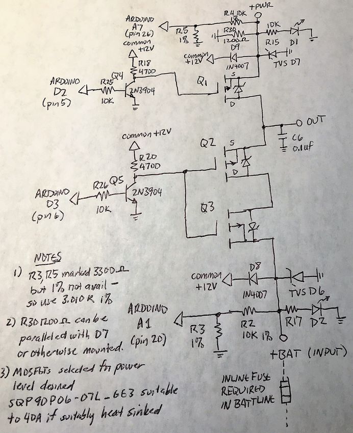
Introduction.

Amateur radio operators involved in emergency communication and others often need to have backup
battery power for their station. It is advantageous if that backup power comes on-line immediately if
there is a loss of AC power. There are excellent commercial solutions that accomplish this goal using
P-channel power MOSFETs and associated circuitry. Some also provide for background charging of
the battery; there is also a commercial solution based on high power Shottky diodes with current-
controllable battery charging --- but these systems come at hefty prices.

This batteryswitcher/smart charger can be built for below $50 and the builder will likely learn a lot in
the process.

There were multiple purposes to this project:

   •   Create an immediate-backup battery switching system ( with such a fast switchover that digital
       or other connections would not be lost)
   •   Provide for charging of the backup battery-- not just “trickle charging” REAL charging
   •   Possibly provide for multiple types of backup batteries, both lead-acid and LIFEPO4
   •   Provide learning opportunities for amateur radio operators in construction
   •   Provide learning opportunities for amateur radio operators in Arduino programming

I recommend that you read this entire manual before attempting to construct this device. Building this
device and setting it up for proper operation requires some level of skill and knowledge

                                         SPECIFICATIONS
           Current handling capacity                 Depends solely on the size of the
                                                     heatsink—can extend to 40 Amps @
                                                     13.8VDC with a suitable heatsink.
           Switch-over time                          Approx. 50 milliseconds
                                                     (software adjustable)
           Maximum AC power supply voltage           15.0 VDC max recommended.
                                                     Beyond 20V, damage is likely to
                                                     occur to the MOSFET gate insulation.
           Battery charging                          User-setting of battery chemistry and
                                                     amp-hours at startup:

                                                         •   Lead acid
                                                         •   Sealed lead acid
                                                         •   Absorbed glass Mat lead acid
                                                         •   LiFePO4, Bioenno type, with
                                                             or without their special

Construction / operation manual                     2                                  August 28 2020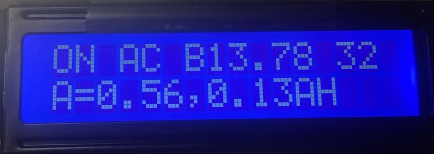
15VDC charger

                                                             Ahr from 5-50+
             Display                                         Inexpensive 2-line 16 character
                                                             display
             Current Monitoring                              Both battery charging current, and
                                                             radio usage current. Measured every
                                                             10 seconds (software adjustable)

             Power Source:                                   13.8-14.5 VDC typical amateur radio
                                                             DC power supply. The higher
                                                             voltage is more important if LiFePO4
                                                             battery is utilized

OBTAINING MAXIMUM BATTERY BACKUP LIFE:

Lead Acid: Keeping a lead-acid type battery in a charged state while providing radio power from a
standard power source may make batteries last longer (potentially up to 6 years1) than our previous
Alachua County technique of using the battery to power the radio and continuously recharge with a
smart battery maintainer.

LIFEPO4: Avoiding continuous maintenance at full charge improves lifespan of these batteries. It’s
best to charge it to a value somewhat below full charge and let it discharge somewhat before recharging
back up. The exact optimum spot is a trade-off between desired backup storage and longevity; some
advise only storing at 50-60% state of charge.

1   https://www.mastervolt.com/determining-the-lifespan-of-a-battery/    Suggesting up to 6 year life span for lead acid
    batteries, down to 80% capacity.

Construction / operation manual                            3                                          August 28 2020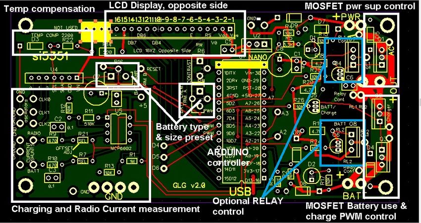
TYPICAL OPERATION

This information is provided here because understanding the usage of this device helps one when
constructing and setting it up.

Be certain to connect AC-based supply, battery, and radio to the proper connections and avoid incorrect
polarity. (Power pole connectors are strongly suggested.)

As soon as either power source is connected, the Arduino will automatically turn on. It goes through
several setup steps:

Step       Description                   User Actions Required
    1      Presentation of GNU GPL       None
           license information and
           software version
    2      Checking quiescent bias on    None. A few millivolts above 0.000 is desirable. Software
           op amp measurement of         remembers the tare value and appropriately adjusts.
           battery and radio current.
    3      Countdown to set battery      During this time, you can adjust the battery chemistry
           chemistry, 5-4-3-2-1-0        trimmer potentiometer with an insulated screwdriver; the
                                         reading is immediately presented. Multiple “zones” in the
                                         angular rotation of the trimmer are defined to allow you to
                                         set the type of battery chemistry

                                          ZONE          Type of Battery          Software Moniker
                                               0      Undefined                  BATTUNDEFINED
                                             (fully
                                          countercloc
                                            kwise)
                                                1       Flooded type lead acid   FLOODED
                                                        battery (with battery
                                                        caps to allow you to
                                                        check and add water)
                                                2       Sealed type lead acid    SEALED
                                                        battery, no way to add
                                                        water
                                                3       Absorbed Glass Mat       AGM
                                                        lead-acid battery
                                                4       Bioenno LIFEPO4          LIFEPO_W_CHGR
                                                        battery using its own
                                                        charger
                                                5       Bioenno LIFEPO4          LIFEPO_ALONE

Construction / operation manual                     4                                  August 28 2020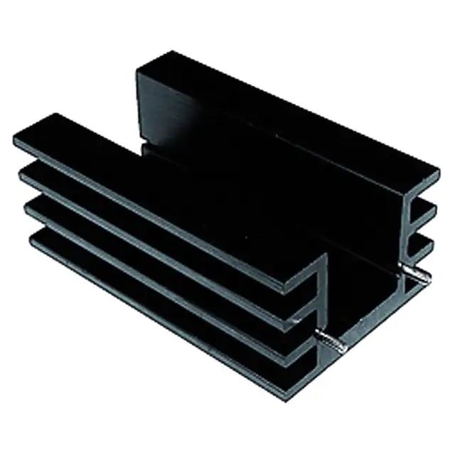
battery without its own
                                                        charger; must be
                                                        charged by this device
                                                6                                 NOBATT
                                              (fully
                                           clockwise)

                                          You must be settled on the correct battery type by the time 0
                                          arrives. If any question, power down the unit and start over.
     4     Countdown to set battery    During this time, you can adjust the battery amp-hour from 5
           amp-hr capacity 5-4-3-2-1-0 to 50 Ahr. For any battery above 50 A-hr, choose the 50
                                       value. This does NOT have to be exact, just within about
                                       10% of the correct value is fine. If you do not get it set by
                                       the 0 presentation, power down the unit and begin anew
     5     Initial measurement of         No required user effort
           battery status, voltage and
           equivalent series resistance
           (except LIFEPO4 using
           external charger)
     6     Proceeds to continuously       No required user effort.
           running normal
           programming

After the setup, the endless loop of normal operation begins.

As long as AC power based supply voltage appears useful, the system will utilize the AC supply.

When the radio current is less than 10Amps (software adjustable) the system will attempt to charge a
discharged battery. If the radio current is above the preset value, the system will temporarily
discontinue charging a discharged battery so as not to place any excessive load on the AC based power
supply.

If the AC power based supply appears to be significantly lower voltage than the battery, the system will
shift to the battery for power; this measurement is made, in general, every 0.050 seconds (50
milliseconds) and changeover takes only a few milliseconds.

Construction / operation manual                    5                                  August 28 2020
During CHARGING from the internal system, the charging current and accumulated charge are
presented. Charging protocol is dependent on battery type and battery capacity. Accumulated charge
is reset to zero anytime the system goes back to AC-based supply from battery usage.
During battery usage, the system will measure the radio current being consumed every 10 seconds
(software adjustable) and present this value, and use it to estimate the total charge removed from the
battery; this assumes that the current was constant during the previous 10 seconds (unlikely to be true
for a single-sideband or CW station).
There is no ON-OFF switch for the system.
The system includes a crude measurement of ambient temperature and adjusts voltage points for lead-
acid chemistry batteries using this; this is only important at very extreme temperatures.
Optimal AC power supply voltage (if adjustable) depends on the type battery being used for battery
backup:
• Lead Acid of any type: 13.8 VDC-14.5 VDC is fine.
• LIFEPO4 using this system as charger 14.5VDC is recommended.
LED Indicators: Understanding their function.
The LED lights provide a visible indication of the voltage present at two points – the +PWR input and
the +BAT input. However, it is important to realize that there are three MOSFETS in series between
these points and that each MOSFET includes a body diode that will definitely carry current from its
anode to the cathode. Further, the system is designed to move current from the +PWR input to the
+BAT terminal in order to charge the battery. Thus….just because an LED is lit does not necessarily
mean that there is a power source at that terminal!
• When the device is powered up for the first time, during setup all MOSFETS are turned OFF
and at this point, the LEDs do indicate whether a power source is present at the input terminal.
• When operating from battery supply, the body diode of the MOSFET connected to the +PWR
terminal will allow current from the battery to light the AC PWR led, regardless of the actual
state of the AC-based power supply.
• When operating from the AC-based power supply, any time there is a charging or testing current
directed at the battery, it will light the battery LED.
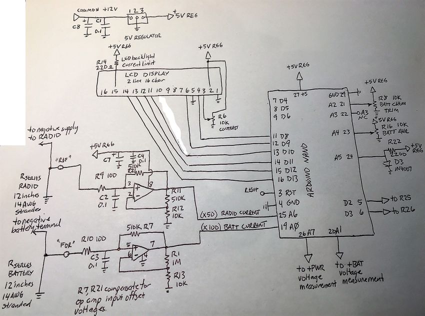
Construction / operation manual 6 August 28 2020SCHEMATIC DIAGRAM Figure 1: Schematic of the logic/measurement portions of the project. Construction / operation manual 7 August 28 2020
Figure 2. Schematic of the output control portion of the project.

Construction / operation manual                    8                August 28 2020
CONSTRUCTION INFORMATION

HEAKSINK NOTES

The choice of the MOSFET heatsink is key to having adequate current capacity for the individual
desired application. Low power radio assets may need only a few amperes capacity; while higher
powered asserts or multiple assets running simultaneously may require up to 40A

       The MOSFETs have an “on” resistance of 0.0067 ohms and will likely drop a lot less voltage
       than even a power Shottky diode. Nevertheless, for high currents (>5A) and CONTINUOUS
       operation (e.g., FM) they require a heatsink. The three power mosfets that would handle this
       level of current are at one end of the board, allowing the easy positioning of some heatsinking.

The power dissipated within each MOSFET is I2R.

This table gives an approximation of the power dissipated by each MOSFET at various levels of
current. During AC operation, a single MOSFET dissipates this power; during Battery backup
operation, TWO MOSFETS are both dissipating this amount, so the total amount is TWICE. While
the junction MUST be kept below 175 degrees, it is advisable to keep the heat sink below 60 degrees C
for operator safety. The thermal resistance between junction and case is approximately 0.5 deg C/watt,
and that of the insulated silicone spacer may be on the order of 0.2 deg C/W – a total of 0.7 deg C/W.
With a heat sink temp of 60 degrees C, and a junction temp of a conservative 150 degrees C, this
allows a dissipation of (150-60) (deg C) / 0.7 deg C/W = 128W

Amperes       Individual      Junction temp     Max thermal      Typical suitable heatsink
              MOSFET          if NO heatsink    resistance of
              dissipation     (25 deg C         heatsink to keep
              = I*I*(0.007)   ambient)          its temperature
                              Junction –        below 60 (on an
                              ambient = 40      individual
                              deg C/W           MOSFET)
                                                (30 deg C amb)
5             0.175 W         32                171 deg C/W      No heatsink required
10            0.7 W           53                42 deg C/W       Heatsink optional

15            1.58 W          88                19 deg C/W       https://www.digikey.com/product-
                                                                 detail/en/assmann-wsw-components/

Construction / operation manual                   9                                  August 28 2020
V5236B-T/AE10802-ND/3511523
20 2.8 W (not safe) 11 deg C/W https://www.digikey.com/product-
detail/en/assmann-wsw-components/
V5220W/AE10798-ND/3511401
30 6.3 W (not safe) 4.7 deg C/W https://www.digikey.com/product-
detail/en/aavid-thermal-division-of-
boyd-corporation/6398BG/6398BG-
ND/1624804
Construction / operation manual 10 August 28 202040 11.2 W (not safe) 2.5 deg C/W Larger heatsink Construction / operation manual 11 August 28 2020
MAJOR FUNCTIONS OF BOARD

    Measure output voltage of AC-based power             Accuracy of approximately 0.1 Volt (calibrated by
    supply                                               user)
    Measure output voltage of Battery                    Accuracy of approximately 0.1 Volt (calibrated by
                                                         user)
    Measure charging current to battery                  Gross measurement of charging current,
                                                         approximate measurement resolution 50 mA;
                                                         based on tapping into a 12” 14-gauge WIRE on the
                                                         negative side of the battery so that we don’t waste
                                                         battery voltage.
    Measure current usage by radio                       Gross measurement of radio current usage;
                                                         approximate measurement resolution 100 mA;
                                                         based on tapping into a 12” 14-gauge WIRE on the
                                                         negative side of the battery so that we don’t waste
                                                         battery voltage.
    Electronically connect/disconnect the AC-based
    power supply to the output terminal
    Electronically connect/disconnect the DC battery     We can choose when the battery is feeding the load.
    to the output terminal
    Electronically control charging of the DC battery
    by the AC -based power supply
    Polarity protection                                  Because of the way the MOSFETs are wired for
                                                         this system we can’t use them for the polarity
                                                         protection (otherwise because of their inherent
                                                         diode, we wouldn’t be able to use them to turn the
                                                         supplies on and off…) but do provide a reverse-
                                                         connected DIODE across the line to blow a series
                                                         fuse if a power supply is reverse connected
    I2C Connection                                       Available, but not used in this current base design.

                                                         This offers immense additional functions. For
                                                         example, an I2C based display could be controlled.
                                                         A frequency synthesizer chip Si5351 can provide
                                                         three digitally controlled synthesized frequencies
                                                         from this board. I2C based
                                                         temperature/humidity/pressure sensors can act as
                                                         altimeters, thermostats,, and even explosive gas
                                                         detectors.

Construction / operation manual                         12                                    August 28 2020
Soldering & Construction
GENERAL WARNINGS
SOLDERING TECHNIQUE
Soldering Iron: Low wattage 25-watt or lower soldering iron with pointed tip and relatively thin
solder is recommended.
If your soldering skills aren’t quite up to soldering the close terminals of the Arduino Nano, work on
simpler portions of the circuit beforehand. Be very careful when soldering the 2N3904 transistors not
to short out their terminals.
STATIC PROTECTION
The MOSFETS specified have a maximum gate-source voltage of only 20VDC and do not have any
zener diode protection built in. They should be considered static sensitive and very carefully handled.
Note that if you are using heatsinks to the side of the printed circuit board, you will mechanically prefer
to have the metal tabs of the MOSFETS pointing AWAY from the board. Q1 and Q2 if mounted on the
top of the board, will face the wrong direction. You can mount them on the underside of the board
which will work properly with their metal tabs now pointing away from the board. Carefully think
through the effect of this to understand the correctness of the pin positions as a result.
Suggested extremely conservative static-sensitive MOSFET -technique:
Place a conductive surface (aluminum foil is useful) below the soldering area. Touch your
hands to it to discharge yourself and then don’t move in your chair or get up. Place the static-
protective delivery packager of the MOSFETS right onto the aluminum foil. Also place the
printed circuit board on the foil – you should only install the MOSFETS after you have already
installed their driving transistors, resistors, and all the protective diodes in the circuit. Do not
install the MOSFETS “first”. They depend on the remainder of the circuitry to help protect
their gates.
I suggest having a few fine strands from stranded hookup wire available, approximately 3” in
length. Remove the MOSFETS from their protective holder directly onto the aluminum foil,
with your hands in contact with it, and quickly wrap a strand of thin wire around the three
terminals from the MOSFET, leaving the ends so that you can remove it later; and snug the
strand up to the plastic body. This strand of wire keeps the gate shorted to the channel and
prevents damage. Now solder the MOSFET into position, considering physical positing to the
heatsink – you will want to AVOID putting significant torque or stress on the wiring when you
physically mount the MOSFET to the heatsinks to avoid possibly delaminating the MOSFET
die internally from the TO-220 tab. Once soldered, remove the wiring strand.
Construction / operation manual 13 August 28 2020Soldering is conventional but requires skill, a sufficiently pointed tip and low-temperature solder. I
prefer lead/tin 60/40 for this purpose but others will prefer lead free despite higher temperatures
required. The secret to not damaging semiconductors is to get enough temperature to the joint
QUICKLY, flow solder, and then WITHDRAW.
Expensive Complicated Semiconductors That Might be Faulty
You may wish to use a socket for the LCD display or the Arduino. Otherwise, I suggest that you TEST
those components before soldering into the printed circuit board. Note the yellow-marked pin areas
where the components are NOT positioned (the PCB has more holes than the devices have pins, so
position them carefully, avoiding the pins that are marked out as non-used).
You can purchase standard sockets easily and carefully cut them off at the appropriate number
of socket holes. But you can’t really abutt two such sockets next to each other in order to “add
them together” as you will have an extra plastic wall where they abut and the spacing will be
wrong right there.
Components that go on the BACK of the printed circuit board
• Remember that the LCD display goes on the BACK side (NOT the side with the silk screen
printing) of the board.
• You probably wish to position the LEDs on the back side also.
Unusual Resistors or Corrections
Construction / operation manual 14 August 28 2020R7/R21 are for the purpose of slightly biasing the op-amp current measurements such that the op-amp inputs are not near enough to zero volts such that the imperfect “offset voltage” of the op-amp would create a dead band. The software measures the offset and takes it into account. R7/R21 can be 510K resistors to create a small positive offset. The MPS6002 op amps have an offset voltage of up to 4 millivolts. The small positive offset created in this circuit will be enough for most but not all of them, but the remaining error in current measurement should be relatively small. R9 and R10 should be 100 ohm resistors, not the 470 that is marked on the board. Construction / operation manual 15 August 28 2020
POLARITY CONCERNS
Semiconductors (diodes, LED diodes, chips, voltage regulator and transistors) have to be inserted the
proper way to operate!

The voltage regulator and the three MOSFET transistors’ screen print shows the direction their heatsink
tab should be when mounted on the top side in order to position them properly. BE CERTAIN YOU
KEEP THE HEATSINK ON THE PROPER SIDE. I blew out several devices once by accidentally
putting the voltage regulator in backwards. You may choose to solder some of the MOSFETS on the
bottom side of the board to physically mount your heatsink --- pay attention to their pin alignment – the
heatsink tab will switch to the opposite side if they are mounted on the bottom side of the board.

Pay careful attention to polarity of electrolytic capacitors. These usually have the NEGATIVE side
marked – which obviously is the opposite of the side that goes to the + mark on the board.
Pay careful attention to the banded cathode of all diodes. The TVS transient suppression diodes
specified for this design are zener-like and DO have a polarity (cathode) that must be observed.
Pay careful attention to the cathode end of Light Emitting Diodes (squared off side of their plastic case)
Almost ANY light-emitting diode will work, so choose those that fit with your preferred mounting. In
my case, I mounted the LED’s on the BACK side of the printed circuit board so that they can be seen
from the front panel along with the LCD display.

U4 is not utilized in this design. The Si5351 is from a previous use of the basic design of this board
for a software controlled VFO.

The largest wire that can be easily soldered for power wiring to the board is #16 stranded. If you plan
to use this for currents above 20 Amps, transition from there to 14gauge as soon as possible.

PLACE A FUSE IN YOUR BATTERY POSITIVE WIRING. This is for safety as most batteries can
produce very large currents if there is a short.

The 5V regulator does NOT need a heatsink. It should NOT get warm. If it does, you have something
wrong.

I suggest to build the base system without any of components for the relays, as those are optional and
involve additional complexity. You might wish later to add the battery-sided relay if necessary.

Be VERY careful not to have solder bridges or shorts particularly at the +PWR or BATT or RADIO
OUTPUT.

Add an additional ground wire (simple stranded hookup wire) from the ground point near pin 1 of the
LCD, over to the ground connections beneath the OP-AMP. This is to improve the ground plane of
the design.

Construct your two #14 12-inch current shunts and carefully connect them to the single point ground
beneath the op amp, and use smaller wire to connect to their tap ends over to the inputs left of the op

Construction / operation manual                    16                                  August 28 2020
amp. I suggest that you add an external bit of wire to well-connect ALL of the ground wires that go to
the ground connection below the op amp.

SUGGESTED BUILDING SEQUENCE

+12VDC Systems/ +5VDC Voltage Regulator

In this section you’ll install the basic power supply systems for the circuitry and test the resulting
regulated power.

   ❒ Install the 5V regulator, paying attention to the correct direction for its heat sink tab.
   ❒ Install C8 electrolytic capacitor
   ❒ Install C1 rf bypass capacitor

   ❒   Install R2 10K 1%
   ❒   Install R3 3.010K 1%
   ❒   Install R17 10K dropping resistor for D2
   ❒   Install LED D2 – note the flat side of the plastic case and match to the silk screening You
       may wish to install this diode on the bottom side of the board, which will face the user along
       with the LCD display. The flat side still needs to be properly aligned.

   ❒ Install D8 1N4007 – paying attention that the band on the diode matches the band on the silk
     screening
   ❒ Install TVS diode D6, again being sure that the band on the TVS diode matches that on the silk
     screening

   ❒   Install R11 10K 1%
   ❒   Install R5 3.010 K 1%
   ❒   Install R15 dropping resistor the LED Diode D1
   ❒   Install D1 LED, paying attention that the flat on the diode matches the flat on the silk screening.
       You may wish to install this diode on the bottom side of the board, which will face the user
       along with the LCD display. The flat side still needs to be properly aligned.

   ❒ Install D9 1N4007, paying attention that the band on the diode matches the band on the silk
     screening
   ❒ Solder a 1200 ohm resistor R30 in parallel with the leads of the TVS Diode D7, with the leads
     close to the body of the diode, but don’t overheat the diode when soldering. After it has
     cooled, install on the board in the proper spot, against paying attention that the band on the
     diode matches the band on the silk screening.

Construction / operation manual                      17                                  August 28 2020
❒ Arrange #16 (or for currents higher than 20A, #14) wiring for battery and AC-based supply.
The ground wires will go to the ground wiring holes near the op amp. Be certain to have an
inline fuse in the battery plus lead, near the battery if possible. I strongly suggested polarity
protected connections, typically POWER POLE connectors.
Once all the above steps have been completed,
❒ Power the circuit briefly from the AC-based power supply and verify that the LED D1 lights up
and that +5V (within 0.1 VDC) shows up at the +5 VDC marked point near the op amp.
❒ Power the circuit briefly from the Battery input (you can use the AC based supply for this
purpose) and verify that the LED D2 lightss and that +5VDC (within 0.1 VDC) shows up at the
+5VDC makred point near the op amp.
❒ Correct any errors in the power supply wiring before proceeding any farther in the construction.
Next install the op amp current measurement section and verify its proper operation
Next install the LCD and temperature measurement diode
Next install the Arduino Microcontroller and verify its proper operation
Finally install the output circuitry – without any of the relay components for now.
Construction / operation manual 18 August 28 2020POWER-OFF TESTS AFTER ASSEMBLY
Before applying any power use a digital multi meter to verify:
• No short from +PWR input to ground.
• No short from +BAT input to ground
• No short from +OUT to ground.
• Very low resistance from the GROUND point near the op-amp, to the grounded (anode) side of
D7 and D6.
CAREFULLY VERIFY
Voltage regulator properly positioned with heatsink tab on the proper side (assuming device mounted
on the top side of the board)
LCD is mounted on the BOTTOM side of the board.
Check every single diode to be certain you have soldered them in the correct direction.
Check every mosfet to be certain you have properly soldered them so that their pins are in the right
spots.
SOFTWARE PREPARATION
Current software as of the time of this writing is version 2.007.
This software does not yet include support for relays.
Software can be downloaded here: http://qsl.net/nf4rc/2020/BatteryBackupVer2.0.zip
In the source code, adjust the value of the resistors (either 3010 or 3300 ohms) depending on
which ones you used for R3 and R5. In my prototype I used 3300 ohm resistors that were only 5%,
but in the Bill of materials I specified inexpensive 1% 3010 ohms:
Adjust the bolded resistor values in the subroutines below to match the resistors that you
actually installed. The publicly released software will be set for the recommended 3010 ohm
1% resistors after August 28 2020
void Read_Battery_Voltage()
{
battery_voltage = (float) BATTERYVOLTAGEFUDGE * ( 5* ((float)
(analogRead(BATTSUPPLYVOLTAGEPIN)) )* (10000 + 3300)/(3300))/1023 ;
#ifdef VOLTAGEOUTPUTS
Serial.print(F("\nBattery Voltage = "));
Serial.println(battery_voltage);
Construction / operation manual 19 August 28 2020#endif
return;
}
void Read_AC_Supply_Voltage()
{
AC_supply_voltage = (float) ACSUPPLYVOLTAGEFUDGE * ( 5* ((float)
(analogRead(ACSUPPLYVOLTAGEPIN))) * (10000+3300)/3300 )/1023;
#ifdef VOLTAGEOUTPUTS
Serial.print(F("AC pin reads: "));
Serial.println((float)analogRead(ACSUPPLYVOLTAGEPIN));
Serial.print(F("\nAC-based Supply Voltage = "));
Serial.println(AC_supply_voltage);
#endif
return;
}
• Compile the software, which should have no errors.
• Using standard Arduino techniques, load the software onto the Arduino. Using a suitable
small screwdriver, adjust the contrast potentiometer so that you can read the LCD.
• You will probably wish to monitor the Arduino output using the Arduino IDE serial monitor
during your original checkout and setup. Set for 115kbaud, 8N1.
INITIAL POWER-UP
The Arduino can be powered from its USB port and the software loaded up without applying any
12VDC power. However the LCD will not light up because it has to get its power from the voltage
regulator.
Apply power only for a second or so, from the +PWR input, and observe the current draw which
should be small (Figure. Example of Screen Display.
ON AC = radio is powered by AC-based supply
B13.78 = current battery voltage is 13.78VDC
Note: On 10 second intervals this automatically reports the AC based
supply output voltage in the same position
A=0.56 = battery is being charged with 0.56 Amps
0.13AH = battery has so far absorbed 0.13AH since charging began
32 = current pulse width modulation is 32/255 duty cycle
CHECK VOLTAGE MEASUREMENT CALIBRATION
Using a sensitive digital voltmeter carefully measure the DC quiescent output of the two op amps,
which should be slightly positive by a few millivolts (not all the way to +5V), with the current shunts
correctly installed.
Once you have the software up and running, experiment with power applied to the +BATT connector.
The system will measure the voltage of both +PWR and +BAT inputs and display on both the serial
output and the LCD Display. It should be fairly accurate. Using simple ratios, if it is not within 0.1
volt make the necessary corrections to the “fudgefactors”
After August 28, 2020, the publicly released software will be set for 1.000 factors
#define BATTERYVOLTAGEFUDGE 0.976 // correction factor for battery voltage
measurement
#define ACSUPPLYVOLTAGEFUDGE 1.010 // correction factor for ac supply voltage
measurement
These should be within a few percent of 1.000.
Adjust the trimmer potentiometers to properly set your battery type and ampere-hour rating.
The setup routine gives you about10 seconds in which to see what it see you as having selected. You
may need a few startup-tries to get these set to your preference. If you are using an external LIFEPO4
Construction / operation manual 21 August 28 2020charger, be sure to select the option that includes the charger; if you wish for the board to charge the LIFEPO4, then select the option that indicates LIFEPO4 ALONE These settings are used to pick the proper charging voltages and currents. MOUNTING Chosen heatsinks can be mounted to the MOSFETS using insulated silicone insulators and insulated bushings and 3mm screws/nuts. The heatsinks if heavy can be further secured to the mounting box after the system is positioned. I chose to use a double thickness of thin aluminum roof flashing as the front panel. Holes were easily drilled into the soft metal, and edges and cutouts made with tin-snips or heavy toenail scissors. Brass standoffs (3mm) of approximately 1.5 cm allowed the display to fit within a cutout. I placed a cardboard shield over the LCD display to guarantee that it did not short out its terminals to the front panel. With the printed circuit board attached to the front panel, the assembly was lowered into the ganged electrical boxes, and the wiring routed through a knockout with a cable securement to avoid any damage to the wiring insulation by the sharp edges. The 12” current shunts were within the mounting box. SOFTWARE commentary SETUP() Turn OFF all the outputs so no current flows until the software is ready to go. Initialize the Serial connection Initialize the LCD display Initialize the global variables sets up a “watchdog timer” (an available function from a library) that if not called within every two seconds….will restart the code. LOOP() (Note that in the Arduino environment, the LOOP function is repetitively executed; you don’t need to write it into a loop as it will loop on its own.) Software actions are carried out on time intervals. Construction / operation manual 22 August 28 2020
•   A call to wdt_reset() is made so that this timer gets reset. If the code hangs, this call will
       fail to be made, causing the watchdog timer to reset the processor.
   •   If the time has advanced to the next_millisecond_time, the AC-based supply voltage, and the
       battery voltage are both measured; if the AC-based supply voltage has declined unacceptably,
       the MOSFETS are switched to connect the battery to the output terminal, and a message is sent
       to the LCD and the serial monitor. using_battery is set to 1 if powering from the battery;
       0 if using the AC powered supply.

   •   If the time has advanced to the (slower) time interval at which the charging system should be
       checked, the battery voltage (which may be in charging mode) is measured, and displayed on
       the top line of the display.
   •   Then, if we are using the AC-based power supply, it is appropriate to consider charging and thus
       the following is carried out:

              Based on the measured battery voltage, the desired_battery_charge_ma is chosen.

              The current charging current is then measured by making a number of measurements of
              the voltage from the current shunt in the negative lead of the battery.

              Changes are then made to the pulse-width-command to be sent to the PWM output pin
              driving the charging MOSFET; this number can vary between 0 (0% duty cycle) and
              255 (100% duty cycle).

              A series of rules are used to slowly advance the actual charging toward the desired
              number; note that the effects of these choices will be evaluated only on the SECONDs
              intervals

              if(instant_current_reading>desired_battery_charge_ma + 100)
              battery_charge_pwm = battery_charge_pwm/2; // cut it way down

                     If we are more than 100 mA above the desired charging current, the duty cycle is
                     cut in half.

              if(instant_current_reading>desired_battery_charge_ma)battery_charge_pwm
              =battery_charge_pwm-3;   // decrease by 1% of our range

                     If we are above the desired charge level, but by less than 100 mA, the charging
                     duty cycle is reduced by 1%

              if(instant_current_reading
A couple of sanity checks finish out the control
if(battery_charge_pwm 255) battery_charge_pwm = 255; // can't go
beyond these limits!
This desired PWM modulation is then sent to the CHARGER pin control using
analogWrite(CHARGER ,battery_charge_pwm);
The next moment in time at which the battery needs to be measured and charging possibly adjusted is
then set.
The loop is now done and repeats. Recognize that the Arduino moves through this loop at FULL
SPEED, hundreds of thousands of times per second, but only stops to carry out our orders at the
appointed discrete time intervals, which are adjustable. Why? Because we wish to minimize radio
frequency interference created by this switching system, and by using slower decision making
intervals, we can reduce the repetitive base frequency of the interference, thus reducing the strength of
harmonics that make it to our radio.
Construction / operation manual 24 August 28 2020FACTORS TO INCREASE BATTERY BACKUP LIFESPAN
Battery Type Desirable factors
Lead-Acid (flooded, sealed, or Avoid discharging the battery below 50%; strictly avoid leaving
AGM) the battery in a discharged state for days or weeks (forms large
sheets of sulfate crystals on plate); strictly avoid overcharging
such that the liquid declines with air access to the tops of the
plates.
Store in a fully charged state and maintain a float voltage.
The software maintains a small trickle charge on all lead-acid
type batteries The voltage chosen is lower for batteries that are
not open to air (that is, flooded cells).
LithiumFePhosphate Avoid storing at full charge due to damage to Lithium plate;
instead store at 50-80%
As of 2.007 the setting is designed to stop charging once the
battery reaches 13.90 volts, and to begin to recharge if it
declines to 13.70 volts – a bit of hysteresis.
TROUBLESHOOTING
Problem Possible Causes
Display cannot be read Contrast setting is not appropriate; re-adjust
Very low battery charging current Battery may already be charged
Lead Acid battery may be sulfated (variable
success by leaving it to charge for several days—
software is set to try this; equivalent series
resistance calculations printed out on the serial
port will demonstrate series resistances >> 100
milliohms.)
Audible hum heard Normal to hear the 500 Hz pulse width
modulation carrier sound.
Construction / operation manual 25 August 28 2020Battery or AC-supply voltage readings are Incorrect values for chosen resistors in
erroneous subroutines; or lack of calibration when originally
constructed.
Both Battery and AC leds light up Normal. See above discussion of operation of the
LEDs and the impact of the inherent body diode
of the MOSFETs
Construction / operation manual 26 August 28 2020You can also read