Large- and small-amplitude shock-wave oscillations over axisymmetric bodies in high-speed flow
←
→
Page content transcription
If your browser does not render page correctly, please read the page content below

Downloaded from https://www.cambridge.org/core. IP address: 46.4.80.155, on 11 Oct 2021 at 00:46:44, subject to the Cambridge Core terms of use, available at https://www.cambridge.org/core/terms. https://doi.org/10.1017/jfm.2021.115
J. Fluid Mech. (2021), vol. 913, R7, doi:10.1017/jfm.2021.115
Large- and small-amplitude shock-wave
oscillations over axisymmetric bodies in
high-speed flow
Vaisakh Sasidharan1 and Subrahmanyam Duvvuri1, †
1 Turbulent Shear Flow Physics and Engineering Laboratory, Department of Aerospace Engineering,
Indian Institute of Science, Bengaluru 560 012, India
(Received 19 December 2020; revised 24 January 2021; accepted 2 February 2021)
The phenomena of self-sustained shock-wave oscillations over conical bodies with a blunt
axisymmetric base subject to uniform high-speed flow are investigated in a hypersonic
wind tunnel at Mach number M = 6. The flow and shock-wave dynamics is dictated by
two non-dimensional geometric parameters presented by the three length scales of the
body, two of which are associated with the conical forebody and one with the base.
Time-resolved schlieren imagery from these experiments reveals the presence of two
disparate states of shock-wave oscillations in the flow, and allows for the mapping of
unsteadiness boundaries in the two-parameter space. Physical mechanisms are proposed
to explain the oscillations and the transitions of the shock-wave system from steady
to oscillatory states. In comparison with the canonical single-parameter problem of
shock-wave oscillations over spiked-blunt bodies reported in literature, the two-parameter
nature of the present problem introduces distinct elements to the flow dynamics.
Key words: high-speed flow, shock waves
1. Introduction
The presence of shock waves in some compressible flow scenarios can lead to flow
unsteadiness. A commonly encountered example of this is the unsteadiness generated
from interactions between a shock wave and boundary-layer flow, where an adverse
pressure gradient imposed by the flow geometry or the shock wave leads to boundary-layer
separation. The separation bubble, described by a separation length scale Lsep , generates
a separation shock that exhibits unsteady oscillatory motion along a region of length Li
upstream of the bubble (Clemens & Narayanaswamy 2014; Kokkinakis et al. 2020). Such
† Email address for correspondence: subrahmanyam@iisc.ac.in
© The Author(s), 2021. Published by Cambridge University Press. This is an Open Access article,
distributed under the terms of the Creative Commons Attribution-NonCommercial-NoDerivatives
licence (https://creativecommons.org/licenses/by-nc-nd/4.0/), which permits non-commercial re-use,
distribution, and reproduction in any medium, provided the original work is unaltered and is properly
cited. The written permission of Cambridge University Press must be obtained for commercial re-use
or in order to create a derivative work. 913 R7-1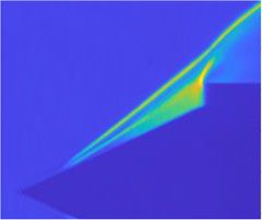
Downloaded from https://www.cambridge.org/core. IP address: 46.4.80.155, on 11 Oct 2021 at 00:46:44, subject to the Cambridge Core terms of use, available at https://www.cambridge.org/core/terms. https://doi.org/10.1017/jfm.2021.115
V. Sasidharan and S. Duvvuri
(a) (b)
Reattachment shock Incident shock
Separation shock
Separation bubble
Separation bubble Separation shock
Boundary-layer edge Boundary-layer edge Wall
Ramp
Li Lsep Li Lsep
Figure 1. A schematic illustration of two canonical flows with small-amplitude shock-wave oscillations.
(a) Bow shock (b) (c)
Separation
region
Spike
D D D
Separation Separation
shock Separation
L shock shock
L L
Figure 2. A schematic illustration of shock-wave unsteadiness in flow over axisymmetric spiked cylinders,
with increasing spike length to cylinder diameter ratio from (a–c). (a) Large-amplitude oscillations (termed
pulsations). (b) Small-amplitude oscillations. (c) Steady shock-wave system.
interactions typically occur in high-speed flow deflection over a ramp/fin/protuberance
or with impingement of an oblique shock onto a surface (see figure 1); here, the ratio
Li /Lsep is observed to be approximately 0.3 (Dussauge, DuPont & Debieve 2006). These
types of flows can broadly be classified under a category of small-amplitude shock-wave
oscillations. In contrast, large-amplitude shock-wave oscillations is the key characteristic
associated with terminal shock unsteadiness over a transonic airfoil (Lee 2001) and buzz
instability in high-speed air intakes (Seddon & Goldsmith 1999).
The canonical and seemingly simple geometry of an axisymmetric spiked cylinder,
shown in figure 2, also exhibits large-amplitude shock-wave oscillations in high-speed
flow for combinations of spike length L and base cylinder diameter D that approximately
fall in the range 0.2 < L/D < 1.5 (see Kenworthy (1978), Panaras (1981), Feszty,
Badcock & Richards (2004a), Panaras & Drikakis (2009), and references therein). These
large-amplitude oscillations, termed as pulsations in literature, are self-sustained and are
characterized by unsteady and periodic shock-wave motion and separated flow along
almost the entire spike length. Interestingly, an increase in L/D into the range 1.5 <
L/D < 2.5 results in distinct small-amplitude shock-wave oscillations, termed simply
as oscillations, characterized by periodic flipping of the leading separation shock wave
between convex and concave shapes (Kenworthy 1978; Feszty, Badcock & Richards
2004b). A steady shock-wave system forms around the body outside of these ranges,
i.e. for L/D < 0.2 and L/D > 2.5 (the values for L/D boundaries cited here are based
on experimental evidence and are found to slightly vary with flow Mach number). The
important aspect to note for this class of spiked-blunt body problems is that the dynamics
is governed by a single non-dimensional geometric parameter, i.e. L/D.
The present work aims to understand shock-wave oscillations in a class of problems with
two geometric parameters. With the exception of a very recent computational study of the
canonical double cone problem by Hornung, Gollan & Jacobs (2021), large-amplitude
shock-wave oscillation problems governed by more than a single geometric parameter
913 R7-2Downloaded from https://www.cambridge.org/core. IP address: 46.4.80.155, on 11 Oct 2021 at 00:46:44, subject to the Cambridge Core terms of use, available at https://www.cambridge.org/core/terms. https://doi.org/10.1017/jfm.2021.115
Shock-wave oscillations in high-speed flow
θ
(a) (b) θ o o (c)
d 45 35 25o 15o
5
M=6 Steady θ = 15o
4 Pulsation 20 θ = 25o
h Oscillation θ = 35o
θ = 45o
D/d (log scale)
3 16
θ
Tu/L
d D
2 12
8
L
1 4
0.5 1.0 1.5 2.0 0 1 2 3 4 5
L/d D/d
Figure 3. (a) Axisymmetric model geometry; (b) L/d–D/d parameter space with classification of shock-wave
behaviour at experimental data points into three states. The solid-line curves represent empirical boundaries
between the states; (c) non-dimensional pulsation time period Tu/L.
have not been subject to detailed study. The geometry chosen for this exercise is a
forward-facing circular cylinder with a right circular conical forebody (see figure 3a).
This geometry can be fully described by three independent length scales – base cylinder
diameter D, forebody cone length L and cone base diameter d – which naturally gives
two independent non-dimensional parameters, taken here to be L/d and D/d. Note that
the cone half-angle θ = tan−1 (d/2L). Flow behaviour across the two-parameter space was
studied by extensive wind tunnel experimentation at Mach number M = 6. Both large- and
small-amplitude shock-wave oscillations were observed in the experiments, and physical
mechanisms are proposed to explain the observations. The following sections present
experimental details followed by results and discussions.
2. Experimental results and discussion
2.1. Hypersonic wind tunnel experiments
Experiments were performed in the Roddam Narasimha Hypersonic Wind Tunnel
(RNHWT) at IISc – a 0.5 metre diameter enclosed free-jet facility (pressure-vacuum type)
that uses dry air as the working fluid and can be operated in the Mach number range
6 to 10. All the present experiments were carried out at M = 6 and a free-stream unit
Reynolds number of 7.7 × 10⁶ m−1 , with a corresponding free-stream velocity u = 900
m s−1 . Stagnation pressure and temperature were set to P0 = 11.1 bar and T0 = 455 K,
respectively, in all cases. At M = 6, the facility provides a usable wind-on duration
of 6 seconds in a single run. Test models with various combinations of D, L and d
were used; for reference, dimensions of the largest model used are D = 100, L = 40
and d = 80 mm. Four different values of L/d = [0.5, 0.71, 1.07, 1.87], corresponding
to θ = [45◦ , 35◦ , 25◦ , 15◦ ], were studied, each at different D/d values in the range
1 < D/d < 5. Note that the conical shock-wave detachment angle at Mach 6 is θd = 55.4◦ .
Shock-wave location and motion were visualized by employing the schlieren technique in
a time-resolved manner by using a high-power pulsed diode laser (Cavilux Smart, 640
nm wavelength, 10 ns pulse width) as the light source and a high-speed camera (Phantom
V1612) for imaging. The short pulse width of the light source allows for a high degree of
spatial localization in imaging fast-moving shock waves. Data was recorded with frame
913 R7-3Downloaded from https://www.cambridge.org/core. IP address: 46.4.80.155, on 11 Oct 2021 at 00:46:44, subject to the Cambridge Core terms of use, available at https://www.cambridge.org/core/terms. https://doi.org/10.1017/jfm.2021.115
V. Sasidharan and S. Duvvuri
rates in the range of 48 000 to 160 000 frames-per-second, and 20 000 frames (images)
were stored from each experiment. The corresponding number of periodic shock-wave
pulsation/oscillation cycles recorded were in the range 400 to 1200 (depending on the
dimensional frequency). The data sets provide good temporal resolution for detailed
analysis of flow features. Figure 3(b) gives an overview of all the combinations of L/d and
D/d studied here; data markers in the figure denote individual experiments. Based on the
shock-wave system behaviour, each location (or data marker) in the L/d–D/d parameter
space is classified into one of three states: steady, pulsations and oscillations. The
terminology used here is borrowed from spiked cylinder literature referenced above, where
pulsations and oscillations refer to large- and small-amplitude shock-wave oscillations,
respectively. The boundary curves between states shown in figure 3(b) are empirically
inferred based on the available data points and are qualitative in nature. Observations and
discussions for the three flow states and transitions between them are presented next. Note
that the terminology of transition in the present context refers to a change in the flow from
one state to another, brought about by changes to the governing geometric parameters.
Hereon, shock waves will be referred in short as shocks.
2.2. Steady shock-wave systems
For any given L/d, it is easy to understand the formation of a steady shock system for
trivial cases at limiting values of D/d, i.e. a large value of D/d (where D/d is sufficiently
greater than L/d) and a value of D/d very close to 1. In the former case, the base cylinder
gives rise to a steady leading bow shock with the conical forebody situated entirely in
the downstream subsonic region. In the latter case, a steady conical shock forms around
the forebody (for θ < θd ) along with a downstream expansion region centred at the base
cylinder shoulder.
Now consider the case of L/d = 0.71, (θ = 35◦ ) for which formation of non-trivial
steady shock systems were observed for D/d 1.3 (see figure 3b). As D/d is reduced
starting from a large value, the bow shock stand-off distance reduces and eventually the
shock moves downstream of the cone tip and leads to scenarios where an attached conical
shock forms on the forebody. The schlieren images in figure 4 show an example of this
for D/d = 1.43 θ = 35◦ , and the key features of the shock structure are schematically
illustrated in figure 4(c) (given the axisymmetric nature of the flow, only the top half of the
flow field is shown in all the schlieren images presented here). The shock structure seen
in the schlieren images can be understood in the following sequential order. The initial
transmitted shock generated at the intersection of the conical and bow shocks impinges on
the boundary-layer flow over the cone surface. The adverse pressure jump across this shock
results in partial separation of the boundary layer and formation of a separation bubble,
which in turn generates a separation shock with a shock angle larger than the conical shock
(angles with reference to the cone axis). It is this separation shock that then intersects the
bow shock and leads to the formation of the final transmitted shock and the steady shock
system seen in figure 4. The intersection point of separation, bow and transmitted shocks
is referred to as the triple point. The nature of interaction between the separation and
bow shocks falls under the type IV classification of Edney (1968). The difference in flow
velocities downstream of the bow and transmitted shocks results in the development of
a shear layer with subsonic and supersonic flow above and below the velocity slip line,
respectively. Downstream of the transmitted shock, a supersonic shock train forms in the
region between the shear layer and the wall, typical of type IV interactions, and this is
referred to as a supersonic jet. It is to be noted that the terminology of shock train is used
913 R7-4Downloaded from https://www.cambridge.org/core. IP address: 46.4.80.155, on 11 Oct 2021 at 00:46:44, subject to the Cambridge Core terms of use, available at https://www.cambridge.org/core/terms. https://doi.org/10.1017/jfm.2021.115
Shock-wave oscillations in high-speed flow
(a) (b) (c) Bow shock
Reattachment shock
Bow shock Sonic line
Slip line
M 1.07. However, an important distinction is
noted – the separation bubble was found to be relatively smaller in size and therefore does
not lead to interaction between the separation and bow shocks, while other features such
as formation of a shear layer and a shock train remain the same. This distinction can be
attributed to the relatively large cone half-angle which results in a stronger conical shock
and lower downstream Mach number, and thereby a weaker transmitted shock that leads to
a more localized separation bubble. For L/d = 1.07 (θ = 25◦ ), a trivial steady state was
observed at D/d close to 1, similar to θ = 35◦ . Interestingly, non-trivial steady states were
not observed for θ = 25◦ at larger values of D/d that are below the D/d threshold beyond
which the bow shock moves upstream of the cone tip; D/d = 3.57, the largest value in
this study for θ = 25◦ , was experimentally found to be very close to the threshold value.
It therefore is concluded that θ = 25◦ cannot support a steady shock system (excluding
the trivial scenarios). Similarly, a steady state was not observed for L/d = 1.87 (θ = 15◦ ),
with D/d = 4.57 being the largest value investigated. It is to be noted that as θ is further
reduced toward the limit θ = 0◦ , the geometry approaches a spiked cylinder, where a
steady state was observed in literature for D/L 5 (Kenworthy 1978); this is a trivial case
with the bow shock standing upstream of the spike tip. This implies that in the scenario
of θ → 0◦ (L d), only trivial steady shock systems are observed at very large values
of D/d where D/L 5. Therefore, by qualitative interpolation of the steady-pulsation
boundary between θ = 25◦ and θ → 0◦ , it is hypothesized that non-trivial steady states
do not exist for θ below a critical value, which lies somewhere between 35◦ and 25◦ .
913 R7-5Downloaded from https://www.cambridge.org/core. IP address: 46.4.80.155, on 11 Oct 2021 at 00:46:44, subject to the Cambridge Core terms of use, available at https://www.cambridge.org/core/terms. https://doi.org/10.1017/jfm.2021.115
V. Sasidharan and S. Duvvuri
2.3. Shock-wave pulsations
2.3.1. Transition between steady and pulsation states
Data from these experiments exhibit a clear trend by which transition from non-trivial
steady to pulsation state occurs with decrease in D/d for fixed L/d and for increase in L/d
for fixed D/d. A physical mechanism to explain this behaviour is proposed by examining
the influence of two parameters: base cylinder shoulder height h = (D − d)/2 and strength
of the attached conical shock. Consider the steady case of L/d = 0.71 (θ = 35◦ ) and
D/d = 1.43 shown in figure 4. Starting with this steady flow, a decrease in D/d for fixed
L/d brings about a reduction in the non-dimensional shoulder height h/d. With that the
bow shock retracts closer to the base cylinder, and thereby the triple point also moves
closer to the base cylinder and further away from the cone axis. The transmitted shock
then impinges on the cone surface (hereon referred to as the wall) at a location closer to
the cone base. Note that the pressure jumps along the shock train and the inward turning
of the wall at the cone base, by an angle (90 − θ)◦ , result in static pressure increase along
the wall downstream of the triple point. The average magnitude of this adverse pressure
gradient is set by the stagnation pressure at the cone base and the distance along the wall
over which the pressure rise occurs. Now with a decrease in D/d, the total mass flow
through the conical shock increases given the increase in distance between the triple point
and cone axis, and for the same reason the mass flow through the bow shock reduces. This
reduction in the mass flow through the bow shock is in addition to the reduction brought
about by the decrease in h/d, which shortens the vertical extent of the shock. Therefore,
a relatively larger mass of fluid with higher total pressure (in comparison with the total
pressure downstream of the bow shock) is introduced by the shock train in the base region.
Hence, the stagnation pressure at the cone base plausibly increases, and certainly does
not decrease, with a decrease in D/d. This leads to the conclusion that a decrease in D/d
brings about an increase in the gradient of adverse wall pressure, chiefly due to the change
in the transmitted shock impingement location. As D/d is reduced below some critical
value, the increasing gradient is expected to induce significant flow reversal near the wall,
and allow for mass influx into the separation bubble and therefore a growth in its size. As
will be seen in § 2.3.2, unsteady growth of the separation bubble drives shock pulsations,
and hence characterizes the onset of pulsations. From figure 3(b), it is observed that the
critical D/d value for this transition lies between 1.43 to 1.19 for θ = 35◦ .
Now consider the reverse transition, i.e. from pulsation to steady state, for decrease in
L/d (increase in θ) at fixed D/d. For instance, at D/d = 1.53, the shock system undergoes
such a transition going from θ = 25◦ to 35◦ . In this scenario, h/d, and therefore the
bow shock stand-off distance remains nearly unchanged, whereas the cone half-angle
increases, thereby increasing the conical shock angle and shock strength. The stronger
shock results in relatively higher total pressure loss, thereby reducing the wall pressure
gradient downstream of the triple point. Further, the reduction in the inward turning
angle at the cone base also alleviates to some extent the adverse pressure gradient along
the wall. Above a critical value of θ (which falls between θ = 25◦ and θ = 35◦ for
D/d = 1.53) these effects curtail flow reversal and arrest the growth of the separation
bubble, and thereby restore stability to the shock-wave system. The above discussions can
be generalized for other values of D/d and L/d where transitions between steady and
pulsation states are observed.
2.3.2. Pulsation mechanism
During pulsations, the shock structure is severely disrupted from its steady state, and the
shock system executes periodic motion with a time period T and amplitudes comparable
913 R7-6Downloaded from https://www.cambridge.org/core. IP address: 46.4.80.155, on 11 Oct 2021 at 00:46:44, subject to the Cambridge Core terms of use, available at https://www.cambridge.org/core/terms. https://doi.org/10.1017/jfm.2021.115
Shock-wave oscillations in high-speed flow
(a) t/T = 0 (b) t/T = 0.09 (c) t/T = 0.18 (d ) t/T = 0.24
(e) t/T = 0.35 ( f ) t/T = 0.40 (g) t/T = 0.51 (h) t/T = 0.55
(i) t/T = 0.60 ( j) t/T = 0.64 (k) t/T = 0.73 (l) t/T = 0.78
(m) t/T = 0.82 (n) t/T = 0.86 (o) t/T = 0.91 ( p) t/T = 0.98
Figure 5. A selection of schlieren images in sequence at 16 different instances over one pulsation time period
T for D/d = 2.14 and θ = 25◦ . A body-fixed reference line (in colour) is provided in all images as a visual aid
to track shock-wave motion (also see supplementary movie file).
to the length scale L of the conical forebody. As a representative example, figure 5 shows a
selection of schlieren images in sequence at 16 different instances over one pulsation cycle
for D/d = 2.14 and θ = 25◦ . The starting point for the cycle, i.e. time t/T = 0 (figure 5a),
is chosen to be the instant where the bow shock stand-off distance and its shape above the
triple point match the bow shock that forms over a forward-facing cylinder of the same
diameter without the conical forebody (which was obtained by a separate experiment). At
t/T = 0, the instantaneous shock wave and flow structure show a close resemblance to a
steady state, like seen in figure 4(a). Growth of the separation region, for reasons outlined
in § 2.3.1, results in upstream motion of the separation point along with a continuous
increase in the separation shock angle, and consequently upward motion of the triple point;
this is seen in figures 5(a) through 5(d). The separation region continues to grow and
distorts the shape of the separation shock, which now begins to resemble a bow shock as
seen in figures 5(e) and 5( f ). During this phase, the bow shock stand-off distance remains
unchanged. Following this, the triple point rapidly moves downstream as it continues
its upward motion, and the separation shock transforms itself into a bow shock, as seen
913 R7-7Downloaded from https://www.cambridge.org/core. IP address: 46.4.80.155, on 11 Oct 2021 at 00:46:44, subject to the Cambridge Core terms of use, available at https://www.cambridge.org/core/terms. https://doi.org/10.1017/jfm.2021.115
V. Sasidharan and S. Duvvuri
in figures 5( f ) through 5(i). Figure 5(i) shows the instance where this transformation is
complete and the newly-formed bow shock fully envelopes the axisymmetric body. At this
point in the cycle, the sonic region around the cylinder shoulder (denoted in figure 4(c) by
a sonic line) reaches its maximum area and allows for a high mass flux. The increased mass
flux around the cylinder shoulder results in a rapid size reduction of the separated region
and thereby a pull back of the newly-formed bow shock (figures 5( j) through 5(n)). The
conical shock re-appears during this pull-back phase and interacts with the retreating bow
shock. Note that bow shock overshoots the reference stand-off distance (t/T = 0) during
pull back and reaches closer to the base; this is clearly seen in figure 5(n) which shows
the instant where the retreating bow shock comes to a stop before reversing its direction of
motion. Following the direction reversal, the bow shock returns to the stand-off position
held at the beginning of the cycle (figures 5(n) through 5(p)) and the next cycle of pulsation
begins.
The key features of shock pulsation are growth of the separation region, deformation
of the shock structure and upward motion of the triple point, and rapid collapse of the
separation region and deformed shock structure. These features were consistently observed
in the schlieren data across the entire region that exhibits pulsations in the L/d–D/d
parameter space. However, changes in relative values of L/D and D/d within the pulsation
region bring about some differences in the deformed shock structures. Particularly for low
values of D/d, close to the transition from pulsations to oscillations, there is no formation
of a large bow shock like the one observed in figure 5. For all the pulsation cases shown
in figure 3(b), the non-dimensional time periods Tu/L were calculated by shock-location
tracking over multiple pulsation cycles, and the results are reported in figure 3(c). It
is interesting to note the steady-pulsation transition boundary trend seen in figure 3(b)
indicates that with increasing θ the shock unsteadiness either completely ceases beyond
some value of θ slightly larger than 45◦ , or is confined to an increasingly small region
of D/d close to 1 until θ = θd . This observation can be attributed to reduction in the
transmitted shock strength with increasing θ (as discussed in § 2.2), which implies that
beyond a certain θ the wall pressure gradient is perhaps not sufficiently strong to induce
flow reversal and trigger large-scale unsteadiness.
2.4. Shock-wave oscillations
Consider the pulsation region of the parameter space for reducing values of D/d at L/d =
1.07 (θ = 25◦ ). At D/d ≈ 1.3, the nature of shock oscillations undergoes a distinct change
from large-amplitude unsteadiness to small-amplitude fluctuations in shock structure.
A mechanism for this transition is proposed by considering the flow behaviour with
increasing D/d starting at the limiting value of D/d = 1, i.e. h/d = 0. As h/d is gradually
increased, a separation bubble begins to grow in the vicinity of the cone base, nested
by the corner. This situation is similar to the canonical problem of high-speed flow
over a forward-facing step (e.g. Murugan & Govardhan 2016), albeit here the step has
a downstream inclination. The separation bubble will be accompanied by the development
of a shear layer in the region over the bubble, driven by the velocity gradient between the
subsonic flow inside the bubble and supersonic flow outside. For small bubble sizes, i.e. for
relatively small values of h/d, this shear layer remains steady, and overall the shock system
is steady. The steady states recorded for θ = 25◦ and 35◦ at D/d close to 1 (see figure 3b)
are representative of this scenario. With increasing h/d, the bubble size increases and
pushes the separation shock upstream along the conical surface, and leads to a longer
development length of the shear layer. Instabilities in the shear layer begin to manifest
and grow beyond a critical value of the development length; this is clearly observed in
913 R7-8Downloaded from https://www.cambridge.org/core. IP address: 46.4.80.155, on 11 Oct 2021 at 00:46:44, subject to the Cambridge Core terms of use, available at https://www.cambridge.org/core/terms. https://doi.org/10.1017/jfm.2021.115
Shock-wave oscillations in high-speed flow
(a) (b) (c)
Expansion waves High
Reattachment shock
Separation shock
Conical shock
Unsteady
shear layer Shear layer Separation region
Low
S S
Figure 6. (a) An instantaneous schlieren image of the oscillating shock system for θ = 25◦ and D/d = 1.26
(also see supplementary movie file); (b) an average (temporal) intensity map; (c) a standard deviation (temporal)
intensity map. Here, ‘S’ denotes the separation point.
figure 6(a) which shows an instantaneous schlieren image for the case D/d = 1.26 and
θ = 25◦ as a representative example for shock oscillations. These instabilities interact
with the separation shock, resulting in small-amplitude high-frequency undulations in
its structure. Further, these shear-layer instabilities are accompanied by small-amplitude
expansions and contractions in the size of the separation region due to impingement of the
unsteady shear layer on the cylinder base, and this results in periodic fore-and-aft motion of
the separation point along the conical surface. The motion of the separation point naturally
imparts unsteadiness to the separation shock. These flow features are collectively termed
as oscillations for the purposes of classification and making a distinction from pulsations.
Figures 6(b) and 6(c) show the average and standard deviation, respectively, of image
intensity obtained from a temporal sequence of 5000 schlieren images for D/d = 1.26 and
θ = 25◦ . The separation shock clearly stands out in the standard deviation map as a region
of relatively large fluctuations in intensity, indicative of the unsteadiness caused due to
its interaction with unsteady shear-layer structures along with the unsteadiness brought
about by the fore-and-aft motion of the separation point (denoted by ‘S’ in figure 6). The
unsteadiness within the separation region is also highlighted by the standard deviation
map.
The size of the separation bubble ceases to scale with D/d beyond a certain threshold,
and a bow shock forms around the base cylinder and interacts with the separation shock.
This brings into play the pulsation mechanisms discussed in § 2.3, and at this point the
shock-wave system makes a transition from oscillation to a pulsation state; this transition
is observed at D/d ≈ 1.3 for θ = 25◦ . This understanding can be generalized for other
values of L/d (θ ) where an increase in D/d starting in the oscillation regions brings
about a transition in the shock system from oscillation to pulsation state, with the D/d
transition boundary dependent on L/d. The pulsation–oscillation boundary trend in the
L/d−D/d parameter space also indicates a narrowing of the unsteadiness regime in D/d
with increasing θ, and lends support to the conclusions drawn in § 2.3.2 on the basis of the
steady-pulsation boundary behaviour.
2.5. Spectral analysis
The contrasting flow features between shock pulsations and oscillations were also studied
by a comparison of the Fourier spectra obtained from time-resolved schlieren data.
Analysis of the spectral content of temporal fluctuations in the local spatial density
gradient (which is captured by schlieren) can give useful insights into the frequencies
associated with flow features of interest (Leidy et al. 2020). Figure 7 presents maps of
913 R7-9Downloaded from https://www.cambridge.org/core. IP address: 46.4.80.155, on 11 Oct 2021 at 00:46:44, subject to the Cambridge Core terms of use, available at https://www.cambridge.org/core/terms. https://doi.org/10.1017/jfm.2021.115
V. Sasidharan and S. Duvvuri
log10(Φ/Φ max) 0 –1 –2 –3 –4 –5 log10(Φ/Φ max) 0 –1 –2 –3 –4 –5
P1 P2
(a) (b) (c)
l=1 1.0 1.0
0.8 0.8
P1
L/4 0.6 0.6
l=1 l
0.04d 0.4 0.4
P2 l=0
l=0 0.2 0.2
0 0
10–2 10–1 100 10–2 10–1 100
0.058 0.058
log10(Φ/Φ max) 0 –1 –2 –3 –4 –5 log10(Φ/Φ max) 0 –1 –2 –3 –4 –5
O1 O2
(d ) (e) (f)
1.0 1.0
0.8 0.8
l = 1 L/4 0.6
0.6
O1 l=1
l
0.02d 0.4 0.4
O2
l=0
l=0
0.2 0.2
0 0
10–2 10–1 100 10–2 10–1 100
0.16 0.16
fL/u fL/u
Figure 7. Power spectral density (Φ) maps of fluctuations in schlieren image intensity. (a) An instantaneous
schlieren image of the pulsating shock system for D/d = 2.14 and θ = 25◦ (reproduced from figure 5a); the
lengths of lines P1 and P2 are 0.71d and 1.18d, respectively. (b) Normalized Φ for data from P1 . (c) Normalized
Φ for data from P2 . (d) An instantaneous schlieren image of the oscillating shock system for D/d = 1.26
and θ = 25◦ (reproduced from figure 6a); the lengths of O1 and O2 are 0.25d and 0.99d, respectively.
(e) Normalized Φ for data from O1 . ( f ) Normalized Φ for data from O2 . Tick marks on lines P1 , P2 , O1 ,
O2 in figures (a) and (d) are in 0.2l increments.
power spectral density (Φ) of image intensity fluctuations for the pulsation and oscillation
cases shown in figures 5 and 6, respectively. In each case, Φ was calculated from temporal
data extracted along two lines of pixels that are indicated in the figure; the lines are labelled
P1 and P2 in figure 7(a), and O1 and O2 in figure 7(d). Lines P1 and O1 are perpendicular
to the cone axis, and lines P2 and O2 are parallel to the respective cone generator line at
the top. For each line, l indicates the normalized distance along the line, with l = 0 and
l = 1 being the end points. In each of the colourmaps, Φ is normalized by its maximum
value Φmax from that colourmap.
In the case of pulsation, a strong spectral peak is seen at a non-dimensional frequency
fL/u = 0.058 for both P1 and P2 (figures 7(b) and 7(c)). As discussed previously,
the pulsation flow field is dominated by the periodic motion of the shock system, and
the same is clearly reflected in the spectra. Note that f = 0.058 u/L = 1/T, where T is the
time period of shock pulsations. The spectral signature seen at the harmonic frequencies
of fL/u = 0.058 merely indicates the fact that image intensity fluctuations produced by
the pulsating shock (and the associated flow) are periodic but not purely sinusoidal.
In comparison with pulsation, the oscillation case presents a relatively broad region of
spectral activity. Data for O1 shows a band of strong fluctuations between l ≈ 0.6 and
913 R7-10Downloaded from https://www.cambridge.org/core. IP address: 46.4.80.155, on 11 Oct 2021 at 00:46:44, subject to the Cambridge Core terms of use, available at https://www.cambridge.org/core/terms. https://doi.org/10.1017/jfm.2021.115
Shock-wave oscillations in high-speed flow
l ≈ 0.8, with activity spread across a wide range of frequencies. This band corresponds to
the spatial location where the separation shock exhibits unsteady undulations, as discussed
in the previous section. This observation is consistent with the standard deviation intensity
map (figure 6c) wherein the region around the separation shock stands out. The spectral
peak in this band is found to be at fL/u = 0.16, and the spectral signature at this
frequency extends down into the shear-layer region until l ≈ 0.2. Hence, fL/u = 0.16 can
be identified as the characteristic frequency of oscillations. Note that data for O2 also
shows a clear spectral signature at fL/u = 0.16. The band of strong fluctuations between
l ≈ 0.2 and l ≈ 0.4 for O2 is indicative of the fore-and-aft motion of the separation
point.
3. Conclusions
Shock behaviour over a conical body with a blunt axisymmetric base is explained by
this detailed experimental study. A steady and two distinct oscillatory states of the shock
system were identified, and the boundaries between these states were mapped out in the
governing two-parameter space. Interplay between the physical effects brought about by
the base cylinder shoulder height (in terms of the bow shock stand-off distance) and the
cone half-angle (in terms of the conical shock strength) determine the nature of shock
unsteadiness and transition boundaries. Large-amplitude shock oscillations (pulsations)
are driven by periodic unsteady growth and collapse of the separated flow region that forms
over the conical surface. Whereas the small-amplitude shock oscillations are primarily
driven by instabilities in the shear layer that forms over a corner separation bubble.
Disturbances in the wind tunnel free stream are expected to not bear a discernable influence
on the observed unsteady flow behaviour. This is supported by the fact that computational
studies of similar shock pulsation/oscillation problems (Feszty et al. 2004a,b; Panaras &
Drikakis 2009; Hornung et al. 2021) are able to reproduce experimental observations with
disturbance-free inflow conditions.
Experimental evidence indicates that below a critical value of θ, which lies somewhere
between 35◦ and 25◦ at M = 6, the flow cannot sustain a non-trivial steady shock system.
Further, shock unsteadiness either completely ceases beyond another critical value of θ
that lies somewhere between 45◦ and θd , or is restricted to a narrow region in D/d for
45◦ < θ < θd at M = 6. Given that the bow shock stand-off distance and the conical shock
strength depend on the free-stream Mach number M, the transition boundaries given by
this study will undergo a shift with changes in M. However, the qualitative features of
shock unsteadiness and driving mechanisms are expected to broadly remain the same.
Supplementary movie. Supplementary movie is available at https://doi.org/10.1017/jfm.2021.115.
Acknowledgements. The authors are thankful to B.M. Shiva Shankar and N. Shanta Kumar for their
assistance in operations and maintenance of the hypersonic wind tunnel facility. This paper is dedicated to
the memory of Professor Roddam Narasimha (1933–2020).
Funding. This work was supported by the Indian Institute of Science through an internal grant (SD).
Declaration of interests. The authors report no conflict of interest.
Author ORCIDs.
Vaisakh Sasidharan https://orcid.org/0000-0001-5537-1966;
Subrahmanyam Duvvuri https://orcid.org/0000-0001-8082-1658.
913 R7-11Downloaded from https://www.cambridge.org/core. IP address: 46.4.80.155, on 11 Oct 2021 at 00:46:44, subject to the Cambridge Core terms of use, available at https://www.cambridge.org/core/terms. https://doi.org/10.1017/jfm.2021.115
V. Sasidharan and S. Duvvuri
R EFERENCES
C LEMENS , N.T. & NARAYANASWAMY, V. 2014 Low-frequency unsteadiness of shock wave/turbulent
boundary layer interactions. Annu. Rev. Fluid Mech. 46, 469–492.
D USSAUGE , J.-P., D U P ONT, P. & D EBIEVE , J.-F. 2006 Unsteadiness in shock wave boundary layer
interactions with separation. Aerosp. Sci. Technol. 10, 85–91.
E DNEY, B. 1968 Anomalous heat transfer and pressure distributions on blunt bodies at hypersonic speeds in
the presence of an impinging shock. FFA Rep. 115. Aeronautical Research Institute of Sweden.
F ESZTY, D., BADCOCK , K.J. & R ICHARDS , B.E. 2004a Driving mechanisms of high-speed unsteady spiked
body flows. Part 1. Pulsation mode. AIAA J. 42 (1), 95–106.
F ESZTY, D., BADCOCK , K.J. & R ICHARDS , B.E. 2004b Driving mechanisms of high-speed unsteady spiked
body flows. Part 2. Oscillation mode. AIAA J. 42 (1), 107–113.
H ORNUNG , H.G., G OLLAN , R.J. & JACOBS , P.A. 2021 Unsteadiness boundaries in supersonic flow over
double cones. J. Fluid Mech. (submitted).
K ENWORTHY, M. 1978 A study of unsteady axisymmetric separation in high speed flows. PhD thesis, Virginia
Polytechnic Institute and State University.
KOKKINAKIS , I.W., D RIKAKIS , D., R ITOS , K. & S POTTSWOOD , S.M. 2020 Direct numerical simulation of
supersonic flow and acoustics over a compression ramp. Phys. Fluids 32 (6), 066107.
L EE , B.H.K. 2001 Self-sustained shock oscillations on airfoils at transonic speeds. Prog. Aerosp. Sci. 37,
147–196.
L EIDY, A.N., N EEL , I.T., T ICHENOR , N.R. & B OWERSOX , R.D.W. 2020 High-speed schlieren imaging of
cylinder-induced hypersonic-shock-wave-boundary-layer interactions. AIAA J. 58 (7), 3090–3099.
M URUGAN , J.N. & G OVARDHAN , R.N. 2016 Shock wave-boundary layer interaction in supersonic flow over
a forward-facing step. J. Fluid Mech. 807, 258–302.
PANARAS , A.G. 1981 Pulsating flows about axisymmetric concave bodies. AIAA J. 19 (6), 804–806.
PANARAS , A.G. & D RIKAKIS , D. 2009 High-speed unsteady flows around spiked-blunt bodies. J. Fluid Mech.
632, 69–96.
S EDDON , J. & G OLDSMITH , E.L. 1999 Intake Aerodynamics, 2nd edn. Blackwell Science (Oxford).
913 R7-12You can also read