MODEL 212 PROFILER OPERATION MANUAL - Document No. 212-9800 Revision E
←
→
Page content transcription
If your browser does not render page correctly, please read the page content below
MODEL 212
                              PROFILER
                            OPERATION MANUAL
                          Document No. 212-9800 Revision E

                 Met One Instruments, Inc
                 1600 NW Washington Blvd.
                 Grants Pass, Oregon 97526
                 Telephone 541-471-7111
                 Facsimile 541-471-7116

212-9800 Rev E                                               Page 2 of 23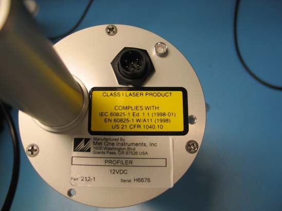
Copyright Notice

Model 212 Profiler Operation Manual
© Copyright 2007 Met One Instruments, Inc. All Rights Reserved Worldwide.
No part of this publication may be reproduced, transmitted, transcribed, stored in
a retrieval system, or translated into any other language in any form by any
means without the express written permission of Met One Instruments, Inc.

Technical Support
Should you require support, please consult your printed documentation to resolve
your problem. If you are still experiencing difficulty, you may contact a Technical
Service representative during normal business hours—7:30 a.m. to 4:00 p.m.
Pacific Standard Time, Monday through Friday.
   Voice:    (541) 471-7111
     Fax:    (541) 471-7116
   E-Mail:   service@metone.com
     Mail:   Technical Services Department
             Met One Instruments, Inc.
             1600 Washington Boulevard
             Grants Pass, OR 97526

212-9800 Rev E                                                          Page 3 of 23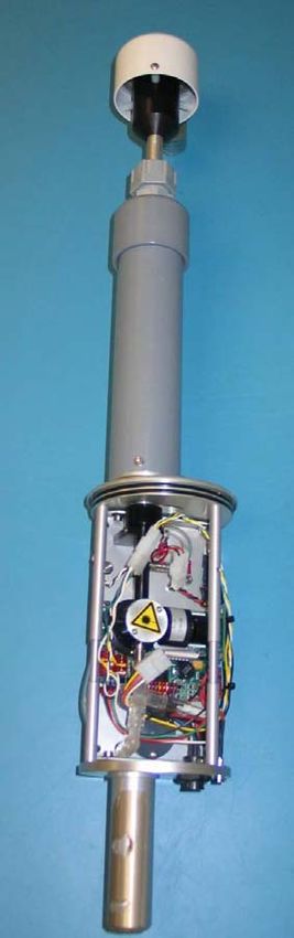
Safety Notice
The contents of this manual have been checked against the hardware and
software described herein. Since deviations cannot be prevented entirely, we
cannot guarantee full agreement. However, the data in this manual is reviewed
regularly and any necessary corrections are included in subsequent editions.
Faultless and safe operation of the product presupposes proper transportation,
storage, and installation as well as careful operation and maintenance. The seller
of this equipment cannot foresee all possible modes of operation in which the
user may attempt to utilize this instrumentation.
The user assumes all liability associated with the use of this instrumentation.
The seller further disclaims any responsibility for consequential damages.

                                     NOTICE

              CAUTION—Use of controls or adjustments or performance of
              procedures other than those specified herein may result in
              hazardous radiation exposure.

              WARNING—This product, when properly installed and
              operated, is considered a Class I laser product. Class I
              products are not considered to be hazardous.
There are no user serviceable parts located inside the cover of this device.
Do not attempt to remove the cover of this product. Failure to comply with
this instruction could cause accidental exposure to laser radiation.
This system contains a laser operating at 650 or 780 nm depending on model.
This wavelength is invisible to the naked eye and can cause damage to the eye if
directly exposed. A protective housing protects the unit. To avoid the possibility
of accidental exposure, always power down the system any time service or repair
work is being preformed.
Repair of instrumentation manufactured by Met One Instruments, Inc. should
only be attempted by manufacturer trained service personnel.

212-9800 Rev E                                                           Page 4 of 23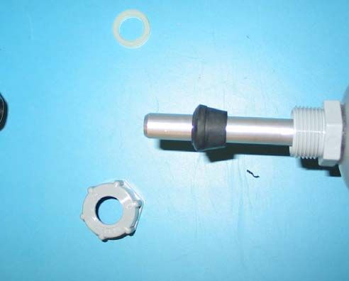
Electrical & Safety Conformity
The manufacture certifies that this product operates in compliance with following
standards and regulations:

      •      FDA / CDRH This product is tested and complies with 21 CFR,
             Subchapter J, of the health and Safety Act of 1968.
      •      European Community (CE) Directive 72/23/EEC
             EN 61010-1 (Safety)
      •      IEC 60825-1 Ed.1.1 (1998-01)
      •      EN 60825-1 W/A11 (1996)
      •      US 21 CFR 1040.10

Warranty
Products manufactured by Met One Instruments, Inc. are warranted against
defects in materials and workmanship for a period of (1) year from the date of
shipment from the factory. Offered products not manufactured by Met One
Instruments, Inc. will be warranted to the extent and in the manner warranted by
the manufacturer of that product.
Any product found to be defective during the warranty period will, at the expense
of Met One Instruments, Inc. be replaced or repaired and return freight prepaid.
In no case shall the liability of Met One Instruments, Inc. exceed the purchase
price of the product.
This warranty may not apply to products that have been subject to misuse,
negligence, accident, acts of nature or that have been modified other than by Met
One Instruments, Inc. Opening the particle counter, e.g. removing the cover,
voids warranty!
Consumable items such as bearings are not covered under this warranty.
Other than the warranty set forth herein, there shall be no other warranties,
whether expressed, implied or statutory, including warranties of fitness or
merchantability.

212-9800 Rev E                                                          Page 5 of 23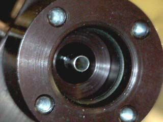
Table of Contents

1.    Safety ......................................................................................................................7
      1.1. Safety Indicators ........................................................................................................................ 7
      1.2. Laser Safety ............................................................................................................................... 7

2.    Familiarization ........................................................................................................8

3.    Installation ..............................................................................................................9
      3.1. Additional Assembly ................................................................................................................... 9
      3.1.1.  Attaching the Aluminum Inlet ............................................................................................... 9
      3.1.2.  Properly seating the heated inlet tube. ................................................................................ 9
      3.1.3.  Attaching the TSP Inlet to the Aluminum Inlet ................................................................... 11
      3.2. Site Considerations .................................................................................................................. 11
      3.3. Mounting .................................................................................................................................. 11
      3.3.1.  Standard camera tripod ..................................................................................................... 11
      3.3.2.  Met One sensor mount ...................................................................................................... 12
      3.3.3.  Mounting bracket ............................................................................................................... 12
      3.4. Wiring ....................................................................................................................................... 12
      3.4.1.   Power................................................................................................................................. 12
      3.4.2.   Communication RS-232 .................................................................................................... 12
      3.4.3.   Special order RS-422 / RS-485 ......................................................................................... 12

4.    Description ........................................................................................................... 13
      4.1. Overview .................................................................................................................................. 13
      4.2. Principle of Operation............................................................................................................... 13
      4.2.1.   Inlet tube Heater ................................................................................................................ 14
      4.3. Specifications ........................................................................................................................... 15
      4.4. Applications .............................................................................................................................. 16

5.    Communication Services for 212 ....................................................................... 17
      5.1. Terminal Service ...................................................................................................................... 17
      5.2. Terminal Commands ................................................................................................................ 17

6.    Inlet Flow Calibration........................................................................................... 19
      6.1. Flow overview (See appendix 2) .............................................................................................. 19
      6.2. Flow Calibration using terminal commands ............................................................................. 19
      6.3. Flow Calibration using the Profiler Utility Program. ................................................................. 20

7.    Software................................................................................................................ 22
      7.1. Appendix 1: RS422 wiring diagram (SPECIAL ORDERS ONLY) ........................................... 23

Appendix 2: 212 Flow Diagram ................................................................................... 23

212-9800 Rev E                                                                                                              Page 6 of 23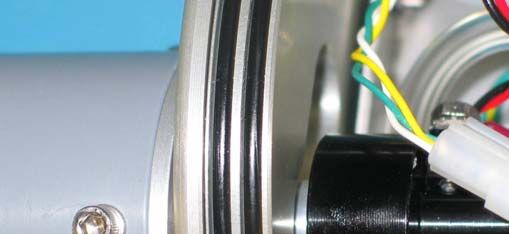
1.      Safety

     1.1.   Safety Indicators
                 This manual uses a CAUTION and a WARNING indication. Familiarize
                 yourself with the following definitions for the meanings of these
                 indicators.
                 A CAUTION indicates a hazard and calls attention to a procedure that
                 if not correctly followed could result in damage to the instrument. Do
                 not proceed beyond a caution indicator without understanding the
                 hazard.
                 A WARNING indicates a hazard to you and calls attention to a
                 procedure that if not correctly followed could result in injury or even
                 death. Do not proceed beyond a warning without understanding the
                 hazard.

     1.2.   Laser Safety
                 This product incorporates a laser diode based sensor that is a CLASS1
                 product as defined in 21 CFR, Subchapter J, of the Health and Safety
                 Act of 1968. This applies when the instrument is used under normal
                 operating conditions and with proper maintenance.
                 Service procedures performed on the sensor can result in exposure to
                 invisible laser radiation. Only a factory-authorized person must perform
                 service on this instrument.
                 The laser diode based sensor inside this instrument has a warning
                 label on it as shown below.

      212-9800 Rev E                                                            Page 7 of 23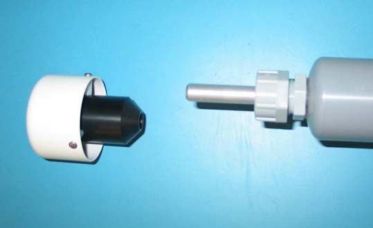
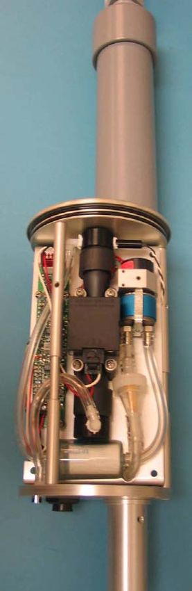
2.    Familiarization
     Figure 1 shows the inside of the 212 Profiler

     Heated Inlet Tube

                                                                    Pump

                                                                   Mass Flow Sensor

                                                                   Pump Filter
      Laser Sensor

                                                                    Zero Filter

                          Figure 1: 212 Profiler (Cover Removed)

     212-9800 Rev E                                                   Page 8 of 23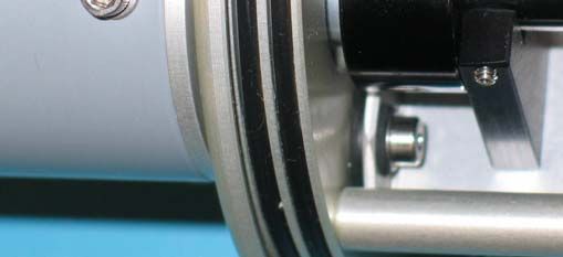
3.      Installation

     3.1.    Additional Assembly

            3.1.1. Attaching the Aluminum Inlet
                  The 212 may be shipped without the aluminum inlet tube being
                  attached to the sensor. Units with the RH controlled inlet heater may
                  come with the heater and inlet tube assembly pre-installed.

                  Insert the aluminum inlet tube into the sample inlet of the sensor. While
                  doing so slightly rotate the aluminum tube until it’s stopped by the
                  sample inlet wall. Connect the white plug from inlet tube to the
                  matching connector from the 212. This is the connection for the heater
                  on the inlet tube for heated units, for non heated units this provides a
                  ground path for the inlet tube.
                  Note: It’s very important to insert the aluminum tube all the way.
                  Only then the O-ring inside the sample inlet properly seals the inlet.
                  If the aluminum tube is not inserted completely, the zero count test
                  might fail due to ambient air leaking into the sample inlet.

        O-ring located inside
        inlet tube receptacle

                                   Close up view of inlet tube receptacle

          3.1.2. Properly seating the heated inlet tube.
      Loosen the grey nut at the top of the heated inlet tube assembly and slide the
      black rubber stopper towards the end.

      212-9800 Rev E                                                            Page 9 of 23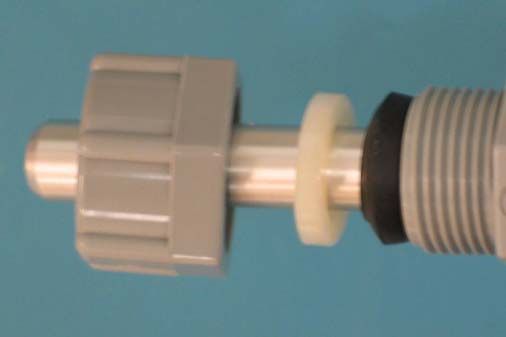
Slide stopper

          Push the inlet tube into the unit. You will feel it connect and seat

                                          Inlet tube
                                          receptacle

          Slide rubber stopper back down install the hard plastic washer and the
          grey nut.

212-9800 Rev E                                                           Page 10 of 23
3.1.3. Attaching the TSP Inlet to the Aluminum Inlet
Note: All units must be operated with the TSP inlet.
Slide the TSP Inlet on top of the aluminum tube of the inlet heater.
Picture of TSP (on the left). Not installed
3.2. Site Considerations
Choose a site free of any nearby trees or other objects.
Non-uniform surroundings (such as a nearby building) create
turbulence, which may affect accuracy.
3.3. Mounting
The Model 212 has hardware features that enable them to be mounted
on a variety of surfaces including a camera tripod, a tower cross-arm,
or a standard Met One wind sensor receiver. Custom mounting can
also be easily fabricated by the user.
3.3.1. Standard camera tripod
The 212 can mount to many normal camera-style tripods through the
¼-20 threaded mounting hole on the bottom of the unit. Met One can
supply a basic camera type tripod as an optional accessory part
number 970650. Make sure that the tripod has a wide enough footprint
to prevent the unit from tipping over. Verify that the sensor cable clears
the mounting face of the tripod you plan to use. If the unit has the
mounting post for a cross-arm installed, you will have to remove it
before installing the tripod.
Attach the tripod to the bottom of the 212 unit securely with the thumb
screw of the tripod. Position the tripod so that the legs are spaced wide
enough to ensure that the unit is stable.
The camera tripod option is not intended for use in windy conditions or
permanent outdoor installations.
212-9800 Rev E Page 11 of 233.3.2. Met One sensor mount
The 212 can also mount to a sensor tower or an 905 Met One tripod as
part of a sensor array. A standard Met cross-arm tube is attached to
the tripod or tower.
The 212 can mount into a standard Met One wind sensor receiver
which mounts on the cross-arm.
The mounting post that inserts into the sensor receiver comes with the
212. The sensor receiver, T-fitting, and cross-arm can be purchased
separately.
3.3.3. Mounting bracket
The 212 can be fitted with a custom fabricated sheet metal or
machined mounting bracket to allow mounting for a post, pole, wall, or
other vertical surface. The bracket can be attached to the 212 through
the ¼-20 mounting hole on the bottom of the unit.
The bracket must be mounted so that the inlet on the 212 is straight
up. Also, the unit should be mounted so that the inlet extends up above
whatever surface the unit is mounted to, otherwise the airflow into the
unit could be impeded.
3.4. Wiring
3.4.1. Power
The 212 is supplied with a 12V power supply. This attaches to the
signal cable through the power jack on the computer end.
Note: When power is connected the 212 will begin sampling.
To record data install the Profiler utility software and press the “Start
Sample” Button – see section 5.
3.4.2. Communication RS-232
The 212 is supplied with a communication/power cable with a DB-9
connector on one end. , It can be connected directly into a 9 pin RS-
232 communication port of a computer.
3.4.3. Special order RS-422 / RS-485
Note: special ordered units can have a RS-422/485 output. If the
output is a full duplex RS-422 protocol. It can also be connected
directly into a 9 pin RS-232 communication port of a computer. See
appendix 1 for details on wiring to RS-422 four wire system. The pin 3
(212 input) of the communication cable should be terminated. If left un-
terminated, random commands can occur due to pick up from the
output line. Install a termination resistor ( 1 kohm or less to ground) on
the RXD A (the 212 input line) if not used.
Example: Only the output (TXD A) is connected to a data logger.
212-9800 Rev E Page 12 of 23The DB-9 connector is wired as follows:
Pin 1: Not used
Pin 2: TXD A
Pin 3: RXD A
Pin 4: Not used
Pin 5: Ground
Pin 6: Not used
Pin 7: TXD B (Special order RS-422/485 only)
Pin 8: RXD B (Special order RS-422/485 only)
Pin 9: Not used
4. Description
4.1. Overview
The 212 Profiler was designed to monitor airborne particle density and
size profile in indoor or outdoor applications. It measures and reports
eight different particle sizes simultaneously. Using the supplied
software utility, the counts or concentration can be displayed and
logged.
It features remarkably simple operation – it starts up by simply
supplying power to the unit – combined with accurate results.
Every 212 is calibrated with NIST-traceable polystyrene spheres in
accordance to accepted industry standards, e.g. ASTM, ISO and JIS.
4.2. Principle of Operation
212-9800 Rev E Page 13 of 23The 212 detects and evaluates the scatter signal from suspended
particulate to provide a continuous real-time measurement of airborne
particulate.
The sample air is drawn into the 212 by an internal rotary vane pump.
Flow rate is controlled with a flow sensor and a pulse-width modulated
feedback system to maintain a constant 1 LPM on the inlet nozzle. An
additional 2 LPM is added around the sample flow (sheath air) to
contain the particles. An internal near-IR laser diode is collimated and
directed through the sample air flow.
When an airborne particle intersects the laser beam it scatters the light
proportional to its cross section. The scattered light is collected over a
wide angle perpendicular to the airflow and laser beam and focused on
a photo diode. The photo diode converts the scattered light signal to a
pulse with a proportional voltage to the particle size.
The output from the photo diode is then analyzed for two criteria.
1. The number of particles that scatter light.
2. The amount of light scattered.
The pulse height is compared against eight levels of programmable
voltages. If the pulse height is greater than the voltage level, the
counter for that channel is incremented.
After the sample time is completed the number of particles in each
channel is reported. The channels report the number of particles of
that size and larger.
4.2.1. Inlet tube Heater
The 212 comes with an inlet heater. This inlet heater is powered
through the unit, and is controlled with an internal RH sensor in the
sample stream.
If sampling in humid environments (i.e. relative humidity >50%)
particles increase in size due to absorbed water. By heating the inlet
tube the water around the particles is vaporized and more accurate
sizing is achieved. Standard RH heater set point is 50%. The set point
value can be read with the terminal command “R” followed by the
“enter” key. The value can be changed with the “R” command followed
by a value and the “enter” key.
212-9800 Rev E Page 14 of 234.3. Specifications
Model Number 212
Measuring Principle Counts individual particles using scattered laser light and calculates the size
by amplitude of scattered light.
Measurement Ranges (Counter) 8 channels that are preset in the range of 0.5μm to 10μm (0.3 optional)
Concentration Range 0-9,000,000 particles per cubic foot
Sensitivity 0.3µm (Counter) Model 212-2
0.5um Model 212-1
Accuracy +/- 10% to calibration aerosol
Sample Air Flow Rate 1 LPM
Sample Interval 1 – 60 Seconds
Operating Temperature 0º to +40º C
Storage Temperature -40º to +80º C
Power 12 VDC, average operating current 180 mA. Maximum is 240mA. (with no
inlet heater).
Inlet heater @ 12 VDC additional 750 ma
Size Diameter: 4”, Length: 7.5” + 12” for inlet tube
Weight 4 lbs
Communications RS-232 or (special ordered: RS-485, selectable full or half duplex)
Serial Settings Baud = 9600, 8 data bits, no parity, and 1 stop bit.
Supplied Accessories Operation Manual 212-9800
Signal/Power Cable 80347
Profiler Utility Software package 9777
TSP Inlet head 9441
Standard mounting post
Power supply 510645 with power cord 400100
Optional Accessories Tripod 970650
212-9800 Rev E Page 15 of 234.4. Applications
Because the Model 212 has many features and can be configured in
many ways, it is finding use in a broad range of applications.
• Clean room monitoring, verification, and filter testing.
• Process control monitoring in sawmills, grain elevators, quarries
etc.
• Mines and ore processing plants.
• Indoor and outdoor air quality studies.
• Finding leaks and sources of contamination air ducts and filtration
systems.
• Concerned citizen groups that want to do their own air quality
studies.
• Hospitals and nursing homes.
• Test the efficiency of residential air purifiers and vacuum cleaners.
• Check filters for particle leaks.
• Epidemiological studies.
• Re-entrainment studies.
212-9800 Rev E Page 16 of 235. Communication Services for 212
The 212 Profiler has two (2) types of serial communication services—Modbus or
Terminal mode.
The application program Profiler Utility uses Modbus. This is the preferred
method of configuration and operation of a 212 Profiler. A Compact Disc (Part
Number 9777) is provided with each unit that contains the Profiler Utility program
and user manual.
The Profile Utility program supports a baud rate of 9600.
The default serial settings of the 212 Profiler are 9600, 8, N, 1.
The Terminal service can be used as required. It has a limited command set. See
the Terminal Service section for a description of the commands.
For more information on the Modbus services, request from the factory the
document entitled OEM 9720 Profiler Communication Specification.
5.1. Terminal Service
Sending three (3) carriage returns (0x0D) starts the Terminal service.
The Terminal service begins by displaying the Unit ID number, the Model
number, and the firmware version/revision number — 12, 9720, 3624-01 R1.9.0.
5.2. Terminal Commands
Command Description
H Display the Help menu
12, 9720, 3624-01 R1.9.0
H - This Help menu
C - Set to Single sample
Y - Set to Repeat sample
Q - Stop command
S - Start command
O - Set Flow offset
T - Set Sample Time
R – Set RH Set Point
X - eXit terminal mode
C Set the unit to operate in Single sample mode.
The unit will run for 1 sample cycle and stop.
The sample time sets the length of the sample cycle.
Y Set the unit to operate in Repeat sample mode.
Repeat mode repeats the sample cycle until a stop (Q) is issued.
The sample time sets the length of the sample cycle
212-9800 Rev E Page 17 of 23Q Quit sampling.
R Report or set the RH set point.
To report the current RH set point setting, send R where is the ASCII
carriage return (0x0D) character.
To set the RH set point setting, send R x where x is the RH set point in %.
The range is 0 to 100 %.
S Start sampling in the Single or Repeat sample mode.
Data is reported at the end of each sample cycle. The report output is useful for
capturing data to a CSV type file. A typical report output follows. Time units are in
seconds since the unit was powered up.
Time,1 (0.49),2 (0.70),3 (1.00),4 (2.00),5 (2.50),6 (5.00),7
(7.00),8 (10.00),Alarms,Flow (lpm),AT (C),BP (mmHg),RH (%)
2540,5563,2755,942,114,39,22,16,0,0
2600,5551,2743,972,135,47,29,17,1,0
2660,5385,2662,898,131,50,28,20,1,18,2.8,23.1,760.2,23
The Alarms value is determined by adding up the values of failed conditions.
For example if the Alarms value is 18 then the Laser Calibration and Temperature
Sensor have failed.
Fail Condition Value
Non-Volatile Memory 1
Laser Calibration 2
Vacuum Pump 4
Air Filter 8
Temperature Sensor 16
Pressure Sensor 32
The Non-Volatile Memory fails when the factory calibration settings are lost. The
unit must be returned to the factory for recalibration.
The Laser Calibration fails when the laser has run for more than 8760 hours.
The Vacuum Pump fails when the pump runs for more than 6000 hours. It also
fails if the pump control is at a maximum and the flow rate is less than 1.0 lpm.
The Air Filter fails when the pump control is at a maximum.
The Temperature sensor fails when the reading is less than –30.0 °C or greater
than 50.0 °C.
The Pressure sensor fails when the reading is less than 600 mmHg and greater
than 772 mmHg.
The Flow, AT, BP, and RH readings only appear if the Profiler Utility software
Report settings have been configured and your hardware has been equipped with
these sensors.
O Report or set the flow system calibration offset.
To report the current flow offset setting, send O where is the ASCII
carriage return (0x0D) character.
To set the sample time setting, send O x.x where x.x is the flow offset. The
range is –4.0 to 4.0 lpm.
T Report or set the sample time.
To report the current sample time setting, send T where is the ASCII
carriage return (0x0D) character.
To set the sample time setting, send T x where x is the sample time in
seconds. The range is 1 to 3600 seconds (1 hour).
X Exit Terminal mode and return to Modbus mode.
212-9800 Rev E Page 18 of 236. Inlet Flow Calibration
6.1. Flow overview (See appendix 2)
The 212 operates with an inlet flow of 1.0 LPM (liters per minute). The inlet air
flow is surrounded by a stream of clean air, referred to as sheath air. This sheath
air keeps the particles from leaving the sample flow stream. This helps keep the
particles from depositing on the optics. The flow rate of the sheath air is about 2
LPM. This gives a total of 3 LPM leaving the optical particle detector (OPD). The
sampled air plus sheath air is then passes through a filter and a pump. After the
pump some of the air is re-filtered and returns back to the sheath air inlet on the
inlet tube. The remaining air is measured with a mass flow sensor and exits the
212 on the bottom of the unit. NEVER BLOCK THE OUTLET PORT. The outlet
port is flush with the bottom of the unit and can easily be blocked with a sticker or
ID tag. The controlling electronics uses the signal from the mass flow sensor and
the internal air flow temperature sensor to calculate the volumetric flow based on
the barometric pressure which was entered into the unit with the profiler utility
program. The 212 does not have a internal baro sensor and flow can change
proportionally with changes in pressure.
Outlet port
6.2. Flow Calibration using terminal commands
The “O” command will adjust the offset flow in the 212. (letter O, not the number
0) The terminal mode can be invoked on unit by pressing the “enter” key three
times. The 212 will return the “>” character (this indicates it in terminal mode). By
entering the “O” followed by a “return” key, the current value will be returned.
This values is most likely around 0.2. The value can be changed by entering the
“O” followed by a numeric value and a “return” key.
Calibration is achieved by attaching a external calibrated flow sensor to the inlet
nozzle and starting the unit in a continues run mode with a “Y” “S” command
(repeat sample mode and a start command). The unit will ramp up the internal
pump. After about a minute a reading should be made on the external flow
212-9800 Rev E Page 19 of 23sensor (convert to LPM if not already in that unit) calculate the difference of the
measured flow from 1 LPM set point flow add this to the current offset value and
enter it with the “O” command. Example: The current offset values is 0.05, the
unit reads a flow of 1.1 LPM on the inlet. Type “O 0.15” and “return” key. Wait
about a minute for the flow to settle down to the new value and repeat until the
flow is 1.00 LPM ±0.01.
NOTE: IF external flow sensor reads zero on inlet but you can feel air
exiting the outlet port. The inlet tube may not be seated all the way see
section 3.1.1
6.3. Flow Calibration using the Profiler Utility Program.
The utility program gives the user much more control of the 212 unit than the
limited set of the terminal commands.
• Start the 212 ‘Profiler Utility’ program supplied with the unit.
• If unit automatically starts sampling use the ‘Red’ button on the utility
program screen to stop the unit.
Start / stop button
212-9800 Rev E Page 20 of 23• Mouse click on the ‘Settings’ pull down screen. Select ‘Flow’ This will bring
up the ‘Flow Settings’ dialog box.
• From the Dialog box, verify that flow mode is set to ‘Actual’. The Flow
sensor type should be set to ‘0 - 5 lpm’. The ‘Use Pressure Sensor’ should
be un-marked.
• Enter Current Barometric pressure from an external reference. The units
may be ether Pascals or “inches of Hg” depending on the setting under
‘Units’. Mouse click the ‘OK’ button when done.
• Attach an external flow sensor to inlet nozzle.
• Start the unit sampling by mouse clicking the green button (it will turn red)
then from the ‘Calibration’ pull down menu select ‘Flow’. This will open the
‘Flow Calibration’ Dialog box.
Close dialog box here
Start unit
• Wait for the flow to reach a steady state. Take the reading from the
external flow sensor . Enter this value in the box labeled ‘Standard’.
Mouse click the ‘Calibrate’ button to enter value into unit. The reported
‘Flow Rate’ will now change to the entered value. The unit will now adjust
the pump voltage to obtain a ‘Flow Rate’ of 1.00 lpm.
• After new value is entered wait until ‘Flow rate’ reads about 1.00 LPM . If
the external flow sensor doesn’t report a flow of 1.0 LPM repeat until a
212-9800 Rev E Page 21 of 23satisfactory flow is obtained. Close the dialog box with the small x button
in the upper right hand corner.
• This completes the flow calibration process.
7. Software
Currently the 212 is shipped with the ‘Profiler Utility Program’.
The Profiler Utility program is used to configure the count channel sizes, and
parameters like the sample time, the sample mode, and the unit ID. This utility
can also be used to log particle counts to a CSV file.
Note: In the Profiler Utility Program manual you may see references to a 9720 or
9722 particle counter. These counters are the sub-modules used within the 212
Profiler. The manual contains some information, which may not apply to the 212
profilers.
.
212-9800 Rev E Page 22 of 237.1. Appendix 1: RS422 wiring diagram (SPECIAL ORDERS ONLY)
B&B electronics
Model 485PTBR
RS-232/RS485
CONVERTER
TD(A) P2
TD(B) 1
6
RD(A) 2
7
RD(B) 3
8
TO COMPUTER RS-232 port TERM 4
9
BAUD RATE 9600, N, 8, 1 SG 5
+12VDC
CONNECTOR DB9
SG
9722 or 212-x
set for FULL D
2
1
Power Jack
12 VDC power
CONVERTER 9722
RD (A) PIN 2
TD (A) PIN 3
SG Ground PIN 5
RD (B) PIN 7
TD (B) PIN 8
Wiring to a 212-x or a 9722 in full duplex
Appendix 2: 212 Flow Diagram
12 V
INLET
HEATER SOLID
HEATER
STATE
CONTROL
RELAY
GND
LPC
PLENUM
CHAMBER
COARSE
FILTER
V EXIT
6V FILTER MASS
PUMP P .2um FLOW
RH TEMP Flow
SENSOR SENSOR SENSOR
MET ONE INSTRUMENTS
212 Flow Diagram
212-9800 Rev E Page 23 of 23You can also read