LAYOUT for WALLS Approved Methods - Habitat Charlotte Region
←
→
Page content transcription
If your browser does not render page correctly, please read the page content below
LAYOUT for WALLS
                                 Approved Methods
                                                July 1,2021

              This manual is a derivative of the copyrighted work of Anna Gallant Carter
              titled Habitat for Humanity Charlotte Construction Manual; Approved Home
              Building Methods. Anna has given the Charlotte Region Habitat for Humanity
              her permission to make this derivative available online on a website accessible
              to the public and in print for the benefit of Charlotte Region Habitat for
              Humanity staff and volunteers as well as other Habitat for Humanity affiliates.
              This agreement does not transfer to Charlotte Region Habitat for Humanity, its
              affiliates, staff or volunteers, the author’s exclusive right to sell, rent, lease, or
              lend copies of the work to the public.

Wall Layout                                    Page 1 of 31                                      July 1,2021
Note to the Reader: Due to differing conditions, tools, and individual skills, the authors of this manual and
Charlotte Region Habitat for Humanity assume no responsibility for any damages, losses incurred, deaths, or
injuries suffered as a result of following the information published in this manual. Although this manual was
created with safety as the foremost concern, every construction site and construction project is different.
Accordingly, not all risks and hazards associated with homebuilding could be anticipated by the authors of this
manual and Charlotte Region Habitat for Humanity. Always read and observe all safety precautions provided by
any tool or equipment manufacturer, and always follow all accepted safety procedures. Because codes and
regulations are subject to change, you should always check with authorities to ensure that your project complies
with all local codes and regulations.

       Wall Layout                                Page 2 of 31                              July 1,2021
Table of Contents
Introduction To The Layout for Walls Section ....................................................................................................................... 4
   Schedule: Layout for Walls Days 1 & 2 ............................................................................................................................. 4
   Crew Assignments .............................................................................................................................................................. 4
   Layout for Walls SafetyGuidelines ..................................................................................................................................... 5
   Task List – Layout for Walls .............................................................................................................................................. 6
      Staffing ............................................................................................................................................................................ 6
      Quality Checkpoints........................................................................................................................................................ 6
   Task List - CuttingPlates ...................................................................................................................................................... 7
      Staffing ............................................................................................................................................................................ 7
      Quality Checkpoints........................................................................................................................................................ 7
   Task List - MarkingPlates .................................................................................................................................................... 8
      Quality Checkpoints........................................................................................................................................................ 8
   Wall Layout Tool, Equipment & Material List ................................................................................................................... 9
      Layout Material List........................................................................................................................................................ 9
   Wall Layout MaterialDescription ..................................................................................................................................... 10
General Instructions For Walls Layout ................................................................................................................................. 11
      Compare Overall Floor Dimensions to the House Plan ................................................................................................ 11
      Exterior Walls - Mark ................................................................................................................................................... 11
      Interior Walls -Mark ..................................................................................................................................................... 12
      Important Things to Remember .................................................................................................................................... 12
      Walls With Plumbing Pipes .......................................................................................................................................... 13
      Letter/Number Code Wall Intersections ....................................................................................................................... 14
      Marking sequence summary ......................................................................................................................................... 15
      Prepare Bottom/Top Plates ........................................................................................................................................... 16
      Inventory Plates............................................................................................................................................................. 16
      Nail Together and Square Cut the End of Plates ............................................................................................................ 16
      Measure and Cut Exterior Plates ................................................................................................................................... 17
      Measure and Cut Interior Wall Plates ........................................................................................................................... 17
      Mark Plates with Letter/Number Code ......................................................................................................................... 19
   Mark Plates for Framing Components .............................................................................................................................. 20
      Exterior Walls ............................................................................................................................................................... 20
      Standard Marking Symbols ........................................................................................................................................... 21
      Component Sizes........................................................................................................................................................... 22
          Framing components ................................................................................................................................................. 23
      Mark Windows.............................................................................................................................................................. 27
      Mark Exterior Doors ..................................................................................................................................................... 27
      Mark Exterior Corners and Ladders .............................................................................................................................. 27
      Mark Exterior wall studs ............................................................................................................................................... 27
   Interior Walls .................................................................................................................................................................... 29

           Wall Layout                                                             Page 3 of 31                                                            July 1,2021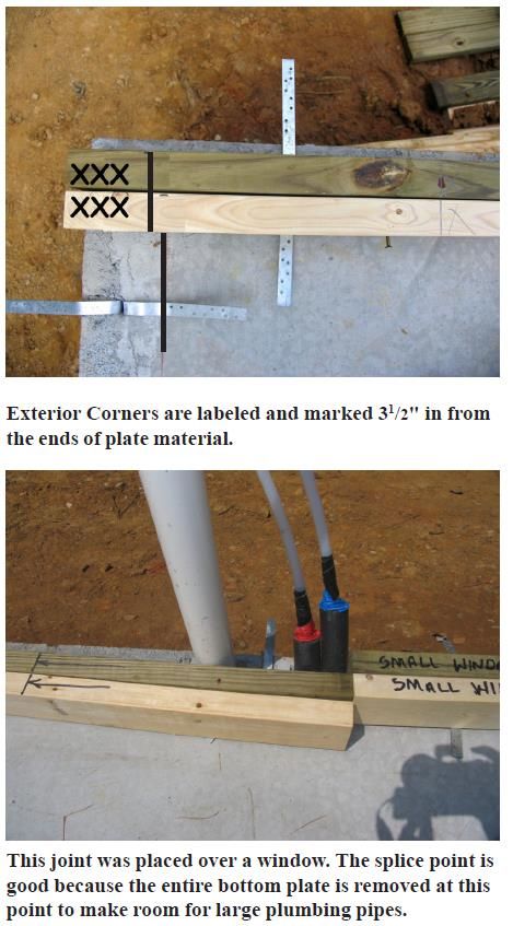
Mark Interior Wall Plates for 24" Centers and Components ........................................................................................ 29
     Mark Interior Doors ...................................................................................................................................................... 29
     Interior Studs ................................................................................................................................................................. 29
  Special Studs ..................................................................................................................................................................... 30
  Final Steps......................................................................................................................................................................... 30
         Precut and Label Cap Plates...................................................................................................................................... 31
             Cap Plate Designations ......................................................................................................................................... 31
  Cap Plate Details ............................................................................................................................................................... 31

Introduction To The Layout for Walls Section
This Section Includes

    •     Schedule and crew assignment
    •     Safety Review
    •     Task Lists
    •     Tool, Equipment and Material List
    •     Material Description
    •     Construction Details and Drawings

Schedule: Layout for Walls Days 1 & 2

On most Habitat projects Layout for Walls can be completed during two scheduled workdays. By the end of the
second workday, the floor will be coded, bottom and top plates for the walls will be temporarily nailed together,
cut to length, coded, marked for components, and ready for the framing crew. Cap plates might also be cut to
length and coded for position. The first floor wall layout for a single story home is a bit more work (all the
rooms are on the first floor) than the work on a 2 story home (where typically the bedrooms and an additional
bathroom are on the second floor).

Crew Assignments

In Charlotte, the layout for walls work is typically done by weekday crews. It is suggested that approximately 3-
5 people be available for layout and 4-5 people for plate preparation and cutting.

          Wall Layout                                                             Page 4 of 31                                                          July 1,2021
Layout for Walls Safety Guidelines
Review these guidelines with each crew member at the start of the day or as they arrive on site.
                 “NO JOB IS SO IMPORTANT THAT IT CAN’T BE DONE SAFELY”
Speak up if something looks unsafe. An observer can spot danger quicker than a worker.
Know where water & a first aid kit are located. Tell the site supervisor immediately in the event of an injury.
Habitat requires that ear protection be used when using power saws.

Habitat requires safety glasses not just when using power saws, but at all times.
Utility knives - keep your hand out of the blade’s path. Retract blade when not in immediate use. A sharp blade
is safer than a dull one. Safely dispose of used blades.

Power Saws:
        Habitat requires that ear and eye protection be used when using power saws. Don’t bind the blade of
        any saw – listen for it. Back off and resupport lumber. Keep electric cords out of the way of the saw and
        out from underfoot.
        Don’t cross hands over to stabilize material on the miter saw. Find another way or get help.
        Guards on saws must be in place & operating.

Remove nails before discarding lumber. Discarded material must be placed in the designated area.
No loose clothing or hair that can get caught in power tools.
Wear appropriate clothing for the task including work boots that protect from falling objects, have a nonskid
sole & resist nail penetrations. No open toed shoes allowed.
Tools must be in a safe condition (meet OSHA standards, i.e. no nicks in cords.)
Think & concentrate on your task.

If you are uncertain about how to do a task, or how to operate a power tool, ask your crew leader.

       Wall Layout                                 Page 5 of 31                              July 1,2021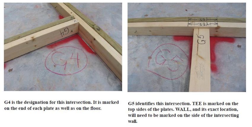
Task List – Layout for Walls

 Staffing

Staff Site Supervisor
Layout Task Leader
4 Additional Volunteers

Tasks to Be Completed and Crew Sizes

      Mark the location of the exterior walls on floor                         2-3 people
      Mark the location of the interior walls on floor                         2-3 people
      Letter-code the wall intersections/corners on floor                      1 person
      Tack bottom and top plates as per the cut sheet                          2-3 people
      Cut the wall plates as per the cut sheet                                 1 person
      Mark the plates for wall studs, tees, ladders, doors, windows, corners   1 person

 Quality Checkpoints

      All walls are marked on the floor with red chalk and sealed
      Errors fully erased
_     Walls are parallel (the measurements between opposite walls of a room are identical).
      Critical dimensions are reviewed (bathtub, hallway, doors)
      2x6 plumbing walls are marked correctly. All pipes fall inside walls on slab floors
      No two intersections have the same letter code
       For wood floor interior walls located over joists or band joist or wood bridging
       Account for toilet, tub, & HVAC return locations
      Wall intersections spray painted
        All the plates are marked for wall studs, tees, ladders, doors, windows, corners

       Wall Layout                                  Page 6 of 31                              July 1,2021
Task List - CuttingPlates

 Staffing

Staff Site Supervisor
Prep Task Leader
2-3 Additional Volunteers

Tasks to Be Completed and Crew Sizes

      Inventory the plate order                                    1 person
      Tack nail together same length of plates and trim plates     2-3 people
      Lay out the plates as per the house cut sheet                3-4 people
       (for slab floors, use treated bottom plated)

 Quality Checkpoints

      Plates are cut accurately, within 1/16"
      All walls have plates in place
      Slab floors have treated sill plate (bottom plate)

       Wall Layout                                  Page 7 of 31                July 1,2021
Task List - MarkingPlates

Staffing

Staff Site Supervisor
Prep Task Leader
1 Additional Volunteer

Tasks to Be Completed and Crew Sizes

      Mark corners of walls                                          1 person
      Mark wall intersections                                        1 person
      Locate windows, exterior doors and exterior ladders            1-2 people
      Mark exterior studs                                            1-2 people
      Mark interior doors and studs                                  1-2 people
      Mark special studs                                             1 person
      Mark interior ladder tees                                      1-2 people
      Transfer letter codes to plates                                1-2 people
      Review layout                                                  1-2 people

 Quality Checkpoints

      All components are proper size and marked clearly
      All intersections have appropriate components
      Exterior wall studs spaced no greater than 24" o.c.on single story houses, 16” o.c on a 2 story.
      Interior wall studs spaced no greater than 24" o.c. for a single story house.
      Interior center hall studs spaced no greater than 16" o.c. for a 2 story house.
      Exterior doors framing are pre-built at the warehouse
      All door openings have 2 studs on either side
      Bathtubs have stud turned sideways centered at 32"
      Letter coding is transferred to top and bottom plates
      All errors are completely erased

       Wall Layout                                Page 8 of 31                               July 1,2021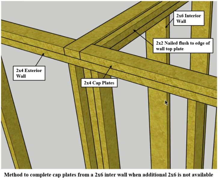
Wall Layout Tool, Equipment & Material List
 Tools Each Layout Crew Member Will Need
 Hammer (16 oz. Min.)                                   Metal Measuring Tape (50-100’)
 Nail Apron                                             Chalk Line (Red Chalk)
 Retractable Utility Knife with extra blades            Chalk Line (Blue Chalk for corrections)
 Retractable Measuring Tape (25' Minimum)               12 Gauge Drop Cord (50')
 Square (Speed or Combination)
  Pencils (2)
  Safety Glasses
 Red & Black Crayon or permanent marker
 Water

 Tools and Equipment Needed On Site                     Jig saw and sharp wood blades
 Twelve-Gauge Drop Cords (100')                         Drill and spade bit of 1”
 Three or Four-Way Electrical Box
 Miter Saw
 Circular Saw
 Saw Table (optional)
 Saw Horses (optional)
 Ear Protection                                         Marking Devices
 Components (or know their sizes)                       Red Lumber Marking Crayon
     Ladders                                            Permanent Markers
     Tees 2x4, 2x6                                      Clear Lacquer Spray Enamel
     Windows (two sizes)                                Floor Plan
     Corners (California Corners)
 Cat’s Paw (nail puller)
 Broom

 Layout Material List
2x4s Bottom Plates (treated for concrete floors)
2x4s Top Plates
2x4s Cap Plates
2x6 Plates for plumbing walls (treated for concrete floors)
16d common nails (these are temporary for securing the top and bottom plates)

         Wall Layout                             Page 9 of 31                             July 1,2021
Wall Layout Material Description
Treated Lumber
      Pressure treated lumber used directly next to any masonry or concrete. Used as bottom plates.

Assorted Lengths of 2x4s/2x6s
       Used for bottom and top plates of walls, as well as for cap plates

Clear Lacquer Spray Enamel
       Used to protect chalk lines when rain is expected

Nails and Fasteners
       16d nails used to temporarily tack nail top and bottom plates together.

       Wall Layout                                Page 10 of 31                           July 1,2021
General Instructions For Walls Layout
Compare Overall Floor Dimensions to the House Plan
Measure and compare overall dimensions of the floor and the house plan before laying out the walls. If the
existing floor dimensions do not match the plan, adjust the plan. Add or remove width and length from
bedrooms, living rooms, or dining rooms. Do not adjust dimensions of bathrooms, utility rooms, or hallways
which have plumbing fixture and/or code requirements. If the floor is more than 1" out of square, causing walls
to not be parallel, let the Site Supervisor know before adjustments are made.
Reminder: Check for square across diagonals, check for parallel by sampling the distance between two walls in
several places.
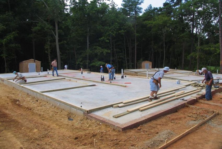
Exterior Walls - Mark
On concrete slab floors, mark 4" in from the outside edge of the foundation and, on wood floors, 3½" in from
the outside edge of the band joist at each end of each exterior wall. For long walls, place an additional mark
midway along the long wall. Using those marks, chalk a red line (red is water-resistant) around the entire
perimeter of the house.
The 4” from the outside wall on slab floors is marked off because the exterior OSB will be flush with the
outside of the slab (3.5” for the plate and .5” for the OSB).
On a wooden floor system, the 3.5” we mark off is because OSB over the wall sits over the band joist and on
top of the sill plate.
Mark on the floor in pencil along the chalked line for exterior doorways and interior wall intersections. Check
exterior doorway locations to be sure that they match porch layouts and that they center on stairs and brick sills.
Hint: On slabs measure from a clean edge of the block and not where concrete or the parge coat has built up.
Wall Layout Page 11 of 31 July 1,2021Interior Walls -Mark
Layout the location of interior walls, marking in pencil on both sides of where the 3½" and 5½" walls are to be
located. Layout long walls (hallway walls) first. Next, layout the walls that extend from the side of the house to
the hall (or other long) walls. Complete the layout of a portion of the house. When certain of the layout, snap
chalk lines to establish the location of the interior wall plates.
Remember that all hallways must have a minimum rough opening dimension of 37½" (36" after drywall
finishing) to pass code. If necessary, take space out of bedrooms to ensure that hallways are wide enough. Make
sure bathroom and utility closets dimensions are not less than required by the plans after making adjustments.
Important Things to Remember
A. Habitat plans show outside walls at 4" because they include sheathing. That is why exterior walls are
chalked 4" from the edge of the concrete foundation wall and sheathed floors, 3½" from the edge of the
band joist.
B. Layout dimensions for all interior walls are 3½" except plumbing walls, which are 5½" wide. On some
floor plans, a section of wall behind the tub will be 5½", stepping back to 3½" to make room for the
bathroom door casing and countertop.
C. Keep walls parallel. If adjustments are necessary, let the Site Supervisor know.
D. Use red or black crayon to circle all pencil layout marks. This makes them easier to find when snapping
chalk lines.
E. Use red chalk to snap lines and be sure the lines are easy to see. If a mistake is made, erase the line,
rubbing it out before remarking.
F. Some dimensions must be exact or must meet a minimum. Examples are as follows:
• Tubs: 601/4" between walls
• Hallways: 37½" rough opening minimum
Wall Layout Page 12 of 31 July 1,2021• Doors: Wall sections that contain doors must be at least as long as the nominal door size plus 8" (4"
each side). This leaves room for door framing and case moldings. Pay particular attention to short
walls that contain doors and doors next to cabinets.
Walls With Plumbing Pipes
On concrete slabs, check the plumbing layout against the house plan. Interior walls will have to be set so
existing pipes are enclosed in the wall. Plumbing walls contain larger pipes and are framed with 2x6s. If wall
locations must be modified, see the site supervisor.
It will be quite a bit easier if you cut the out the 2x6 opening to allow the built wall to slide in over the
plumbing pipes. Always cut from the same side. Raising and maneuvering the built wall over the pipes is not
something that is easy to accomplish.
Wall Layout Page 13 of 31 July 1,2021Letter/Number Code Wall Intersections
The intersection of walls and points where walls terminate must be coded and marked on the floor with a
letter/number designation. This code will also be written on the top & bottom plates of wall sections. The coding
system must be logical and consistent to make sorting and placement of wall plates (and later, framed walls)
easy. The marking with letter and numbers on the floor and on the plates of all walls is typically done by the site
supervisor or an AmeriCorp member. Since cap plates are sometimes cut (if time permits) before the house is
framed, the coding system must also facilitate the sorting and placement of the cap plates, which is described
later in this section. The number/letter system described below can be marked on a copy of the floor plan and
given to the Site Supervisor for reference.
The preferred coding system designates intersections using letters for walls that run front to back and numbers
for walls that run side to side.
Facing the house, the left most exterior wall is wall letter A. The next, parallel interior wall is wall letter B.
Successive, parallel (or close to it) walls are designated with letters C,D,E, and so forth until the right most
exterior wall is assigned a letter.
Walls that run from the left to the right side of the house are designated by numbers. The sequence starts at the
rear of the house, therefore, the back most exterior wall is designated as wall 1. The next interior side to side
wall is designated as wall 2 Successive, parallel walls are designated 3,4, and 5 and so forth until the front
exterior wall is designated.
Hint: Letters and numbers that might be confused can be skipped. Examples are I, H, L, M, N, 6 and 9. If they
are used, they should be underscored so that “I” is not confused with H, L with V, M with W, or N with Z.
The intersection of exterior walls at the back left corner of the house would be coded as A1. The intersection of
the left most exterior wall A with interior wall 2 would be coded A2. Use a broad tipped red permanent marker
or crayon to mark the letter/number code at each intersection or termination point of a wall. Make sure that the
letter/number codes are large and easy to see. If walls will not be raised soon or if rain is expected, spray all
intersections and letters with clear lacquer spray enamel.
Wall Layout Page 14 of 31 July 1,2021Marking sequence summary
• Walls that run front to back are marked in order, starting on the left, with letters.
• Walls that run side to side are marked in order, starting with the rear, with numbers.
• The codes are marked on the floor at each intersection and on the plates.
• Walls that are close to being in line can share the same letter or number.
• Letters that can be confusing, H and I for example, should not be used.
Wall Layout Page 15 of 31 July 1,2021Prepare Bottom/Top Plates
Inventory Plates
Check the house plans to determine the appropriate exterior wall plate lengths and where top plate joints should
occur, which usually is over a window component. Some joints may occur along a length of wall, and if so, wall
framing can be strengthened by placing studs at the end of each wall section to be joined, enabling back to back
studs that can be nailed together when adjoining wall sections are raised. Inventory the lengths of all plates
designated on the house plans and ensure that framing material of adequate length and quantity is on site to
fabricate top and bottom plates per the house plan. Bottom plates for concrete slab floors must be treated wood.
Nail Together and Square Cut the End of Plates
Temporarily nail all plates together with 16d nails (do not drive all the way through). The plates do not need to
be crowned. It is helpful to mark the nominal length (8, 10, 12, 14, or 16 feet) on the plate. Nail plates so that
one end is flush; then trim the other end flush if necessary. Remember, for slab floors, bottom plates must be
treated lumber.
Wall Layout Page 16 of 31 July 1,2021Measure and Cut Exterior Plates
It is helpful to have one or two designated cutters and at least two other people measuring and placing plates
once they are cut. Ask the site supervisor for a cut sheet.
Exterior plates should be cut first, beginning with side walls. Cut plates per Habitat’s cut sheet. This will ensure
that exterior wall plates are as long as possible with joints breaking at window components and that foundation
straps and bolts are within 12” of the end of every plate. Remember when determining where joints are placed
that cap plates must overlap top plate joints by at least 4' and break over a stud or a header.
Side wall plates extend to the outside edge of the band joists on wood floor (or for a slab ½" short of the outside
face of the foundation). In other words, the long walls run long. Mark 3 ½" inches in from each end of the side
wall plate. This line will match up with the intersecting wall’s chalk line. Determine the length of plates by
measuring accurately along the chalk lines. Lay plates along the exterior walls on their sides with the top plate
facing in. Plates should butt tightly.
Measure and Cut Interior Wall Plates
Using the cut list measure for and cut plates for the longest walls (usually hallways) first. This is also done from
Habitat’s cut sheet. Place plates on the layout lines as they are cut. Continue measuring and cutting, finishing
with the shortest walls. Place plates on their sides along their layout lines Check the floor plan to make sure no
walls have been left out. Plates should butt tightly.
Wall Layout Page 17 of 31 July 1,2021Wall Layout Page 18 of 31 July 1,2021
Mark Plates with Letter/Number Code
After plates are laid out on the floor, mark the top and bottom side of the plates on the end that matches the wall
intersection point with the appropriate letter/number code. Plates that do not end at a wall intersection can be
marked with the first symbol being the same as the wall number or letter and the second symbol being a W, X,
Y, or Z. For example, the first joint in the plates along the left exterior side wall, number 1, would be 1W, the
next joint, 1Y, and so forth.

Designations should be marked on the floor and also on both ends of each plate section.

       Wall Layout                                 Page 19 of 31                               July 1,2021
Mark Plates for Framing Components
Exterior Walls
Mark Exterior Side Wall Plates for 24" Centers (for single story homes); 16” for 2 story homes.
Check the placement of the plates along the exterior side walls to be sure that they are turned on their edges,
match layout lines, and are tightly butted. Using a steel tape and a carpenter pencil, place marks on the top edge
of the plates on 24" centers, starting at the back of the house and working toward the front. The first mark should
be 231/4" from the end, the next, 471/4", the next, 711/4" and so on. These marks are preliminary and mark the
edge of studs and other framing components. Place an X to the right of these marks to designate the stud should line up
with this line. Leave the last four feet unmarked. For 16” exterior walls use the following markings: 151/4" from
the end, the next, 311/4", the next, 471/4" and so on. Once completed and double checked with house plans you
can go back and trace the marks with a marker.
Front and back walls butt into side walls. When marking front and back walls for studs, hold the tape 31/2" past the
end of the plate.
Next, go to the front of the house, holding the tape 3 ½” past the plate mark lines at 23 ¼” , 47 ¼ ", and 71 ¼”
from the end of the plates. Marking the last four feet in this manner allows the corner sheathing to have its
4
interior edge fall on the center of a stud. (Corner bracing starts flush with the corner framing member. The OSB
edges do not overlap.) Check this in both directions off each corner. For 16” exterior walls use the following
markings: 15 ¼” from the end, the next, 31 ¼” the next, 47 ¼” and so on. Place an X to the right of these marks to
designate the stud should line up with this line.
Lingo Tip: When pulling a tape from the back of the house, “Laying Ahead” means that when marks are placed
for 16" o.c., they are made 3/4" before the 16" mark (151/4"), with the “X” for the stud “laying ahead” of the
mark.
Wall Layout Page 20 of 31 July 1,2021Standard Marking Symbols
Use standard symbols and notations when marking plates for framing components. Arrows drawn to the layout
lines on the plates show where to place prefabricated components.
·Single Studs | X|
·Double Studs |X|X|
·Corners |COR| or |XXX| or |CALI|
(XXX can denote solid exterior corners, whereas CORN can be used for corner components for interior corners
that are not solid.)
·Beam Pocket |BEAM POCK|
·Wall | WALL |
·Interior Doors ||
·Windows || OR ||
·Field built ladders || when a standard ladder does not fit the stud locations on
the layout, a field built ladder is constructed to the exact needed measurement.
This can be a standard ladder component cut down to size, or built entirely from
materials available on site.
See Layout Diagram for an example of a floor layout.
Wall Layout Page 21 of 31 July 1,2021Component Sizes
Window components come in two sizes (see floor plan). When measuring for the window add 6" to the window
size to determine the component size. (This may vary depending on the window manufacturer.) For example, a
2’-8" (32") window would have a component size of 38" – allowing for a king and jack stud on each side of the
window. Mark the outside dimensions of the window components with black marker and label with the words
|WINDOW| or |SHORT WINDOW|. On a 2 story home, there is an extra jack stud on each side of the window.
2’-8" x 4’-4" = 38" outside dimensions
2’-8" x 3’-0" = 38" outside dimensions
Exterior door components are also pre-built and come in two sizes. To determine exterior dimensions of the
components, take the actual door size (see plan) and add 8". On a 2 story home, there is an extra jack stud on
each side of the door.
3’-0" door (36") = 44" outside dimensions
Ladders on a 2 story home are 17½" wide and are placed within the 16" o.c. stud layout, allowing the
intersecting interior wall to attach at any point within the ladder. Standard ladders are 25½” wide placed within
the 24” OC stud layout.
Tees are 6½" wide for 2x4 walls and 8½" for 2x6 walls.
Corners are made as California corners using two studs perpendicular to one another. On a 2 story home the
corners on the long walls of the first floor are made at the warehouse and are 3 wide.
Interior Doors do not come as components and are laid out to provide an opening 2" wider than the nominal
dimension of the door (a 28" door would have a 30" opening). Mark for two studs on each side of the opening.
Below are examples of various components:
Wall Layout Page 22 of 31 July 1,2021Framing components
Site Location:
QUANTITY ITEM LENGTH EXAMPLE
_______. LADDER WALL ___. 2”x 4”x93”
TEE ___. 2”x 4”x14 ½” Spacer
___. 2”x 8”x14 ½” Spacer
On 8’ high walls: center
down from top plate: 24”,
48”, 72”;
_______. INTERIOR WALL ___. 2”x 4”x93”
TEE ___. 2”x4”x16” Spacers
Wall Layout Page 23 of 31 July 1,2021_______. BEAM POCKET ___. 2”x 4”x93”
___. 2”x 4”x 83 ½”
___. ,5”x83 ½” OSB
_______. INTERIOR CORNER ___. 2”x 4”x93”
___. 2”x 4”x16” Spacer
_______. EXTERIOR DOOR ___. 2”x 4”x93” or King *2
___. 2”x 4”x 80¾”
Wall Layout Page 24 of 31 July 1,2021_______. EXTERIOR ___. 2” x 4” x 36” for
WINDOW 3’x5’ window
REGULAR ___. 2” x 4” x 24” for
2’x3’ window
_______. EXTERIOR Measure cripples for top of
WINDOW SMALL header and under sill after
assembly of other
components.
_______. INTERIOR DOOR ___. 2”x4”x 93” x4
KING STUDS
_______. CALIFORNIA ___. 2”x4”x 93” x2
CORNERS
Wall Layout Page 25 of 31 July 1,2021Layout diagram for a 2 story house
Wall Layout Page 26 of 31 July 1,2021Mark Windows
Next, using the house plan, determine where window components should be positioned. Unless a specific
dimension is on the plan, make slight adjustments so that a 2x4 stud side of the window component matches an
exterior wall stud mark. Do not adjust bathroom and kitchen windows. Instead, use any dimensions found on
the plans as cabinets, sinks, and furniture arrangement often determine the placement of windows. Also,
maintain symmetrical placement of windows on front house walls. To ensure symmetry when multiple windows
are installed in the front of the house, reference the house plans. You want to make sure that the windows are
not too close to the door, allowing the installation of the window shutters to fit.
When window layout is certain, use a speed square to mark the location of the outside edge of the window
components and place a
or
symbol between them.
Mark Exterior Doors
Next, transfer the location of exterior doors components to the exterior wall plates. Be sure of the size of the
door to be placed in the opening and make sure that doors are centered over brick sills, match porch layouts, and
center on stairs leading to them. Some doors must be centered in the front wall to ensure a symmetrical
appearance for the house. Using a speed square, mark the outside edge of the door component and mark a symbol between them.
Mark Exterior Corners and Ladders
Exterior Corners are marked with CALI to designate an L shaped corner. On a 2 story home, the exterior
corners are simply 3 studs nailed together and they come from the warehouse.
Exterior Walls receive Ladders where they intersect with interior walls. The edge of the plate is marked WALL
at the appropriate location where the adjoining wall intersects. Ladders are adjusted so one of the studs in the
component falls on a 24" stud layout mark. If the width of the ladder must be altered due to an adjacent
component, it should be labeled accordingly and built on site. Mark these as FB Ladder
Mark Exterior wall studs
Finally, using a speed square, mark the location of the edge of studs and place an X on the side of the line that
the stud should be positioned.
Remember to locate and mark for regular corners, beam corners, and beam posts. Erase any layout dots that fall
Wall Layout Page 27 of 31 July 1,2021inside components.
Mark Exterior Back and Front Wall Plates for 24" (for single story homes); 16” for 2 story homes
Layout of these walls can occur simultaneously with side wall layout.
Check the placement of the nailed together plates along the exterior front and back walls to be sure that they are
turned on side, match layout lines, and are tightly butted. Using a steel tape and black marker, place dots on the
top side of the plates on 24" centers. Start at the left side (facing the house) of the house and work toward the
right.
As previously outlined, one person should hold the tape with the 3½" mark even with the left end of the plate:
a. For 24” o.c. long walls (front to back) place lines at 231/4" from the end, the next, 471/4", the next, 711/4"
and so forth. For the side to side walls, the tape should be moved to the right end of the plate, held on the
3½" mark, placing lines at 231/4" from the end, the next, 471/4", the next, 711/4" and so forth. These lines
are preliminary and mark the edge of studs and other framing components.
b. For 16” o.c long. Walls (front to back) place lines at 151/ 4", 311/4", 471/4", and so forth. For the side to
side walls, the tape should be moved to the right end of the plate, held on the 3½" mark, and lines placed
at 151/ 4", 311/4", 471/4. These lines are preliminary and mark the edge of studs and other framing
components.
Similar to the marking of side wall plates, locate and mark wall intersections, Tees, Windows, Doors, Beam
Pockets and Corners, and Studs.
Wall Layout Page 28 of 31 July 1,2021Interior Walls Mark Interior Wall Plates for 24" Centers and Components Check the placement of the plates for interior walls to be sure that they are turned on edge, match layout lines, and butt tightly together. Start with long (hall) walls at the back of the house and work toward the front of the house. Use a metal tape and black marker to temporarily mark the plates for studs 24" on center. The first mark should be 231/4" from the end of the plate, the next 471/4", the next 711/4", on so forth until the end of the plate is reached. Walls running perpendicular to the side of the house should be marked similarly, starting at the outside walls. Short walls should also be marked for stud and component placement using 24" stud placing. After preliminary 24" centers are marked, ends of plates should be checked and marked for a stud (X) or a Corner (CORN). Where walls intersect a plate, layout lines should be transferred from the floor to the plate using a speed square. The layout lines should be transferred to both sides of the plates and should be marked with a | WALL | symbol in pencil. After the wall symbol is placed on the plate, two additional lines, spaced 1½" to either side of the | WALL | symbol should be placed on the plate to indicated the outside edges of the Tee component. The plate then is marked with a tee symbol, ||. The side of the plate that receives the intersecting wall is marked with a | WALL | symbol. Mark Interior Doors Next, review the plan to determine door locations, sizes, and which side will be the hinge side. Framing for interior doors is two inches more than the size door specified on the plan. Cased openings, where no door is to be installed will be dimensioned on the plan, giving the dimensions of the rough opening. Door layouts are marked on the plates after wall locations and Tees are marked. Doors are framed with double studs, | X | X|, on each side of the opening. The hinge side normally will be adjacent to an intersecting wall and one stud can be the stud that helps makes up the Tee. Door openings should be marked with the appropriate symbol, such as
Special Studs
Plate Joints
A stud needs to be added on the end of each wall section where they are joined.
Bathtubs
Centered at 32" from the back of the bathtub, turn one stud sideways and nail flush with the bathroom side of
the wall (for bathtub installation). Do this on each side. Note: Check size of bathtub to insure 32" dimension
supports the nailing flange.
Kitchen Pass Through
Mark a “CORNER” at the free end of any pass through. Check the plan for the exact width of the opening and
mark accordingly. All studs that fall under this pass through should be 43½" and marked “C” (Cripple). Those
that fall over the header should be 10" and marked “C”.

Final Steps
Review Layout Carefully
Check all door and window measurements. Make sure all exterior wall intersections have a Ladder and interior
wall intersections a Tee.

Check bathrooms for special stud locations. Check exterior walls for 24" (or 16” for 2 story homes) o.c. and
interior walls for 24" o.c. stud placement.
Pull a tape on all exterior walls and make sure there is 2x4 centered at every sheathing joint.

Cut Bottom Plates for Penetrations
Bottom plates will need to be cut or drilled for penetrations such as bolts and plumbing lines. Mending plates
can be nailed onto the side of a bottom plate if necessary. It is best to minimize cutting of the bottom plate as
much as possible. Leaving a 1/4” gap around the penetrating object is sufficient if it is placed accurately. If a
bottom plate must be completely cut away, extra studs can be placed on either side of the cut out section to
reinforce the wall.

       Wall Layout                                 Page 30 of 31                                  July 1,2021
Precut and Label Cap Plates
If cap plates are to be precut and labeled before the house is framed, measuring is done during the house layout
exercise. A method of identifying and labeling cap plates and marking the floor where they are to be placed atop
a wall is necessary.
Cap Plate Designations
The system for identifying the cap plates is based on the system used to letter and number the walls of the
house. The left most exterior wall under the previously described system is wall lettered as A. Starting at the
back of the house and working toward the front, the first cap plate along wall designated as A is identified as
cap plate A- 1, the next as A-2, and so forth. Similarly, the back wall of the house is designated wall 1 Starting
at the left side of the house and working to the right, the first cap plate is designated as cap plate 1-1, the next as
1-2, and so forth.
If the last cap plate along a wall extends over a porch beam, it is not precut. After the house is framed and the
porch beam is installed, the last cap plate is measured, cut and installed.
Once cap plate designations are determined, the symbol identifying the cap plate should be marked on the floor
and also the top of the top plate with either a black marking pen or crayon. The black color will differentiate the
symbol from the red symbols, which designate wall intersections.
A list of cap plates can be made on a sheet of paper in an orderly manner and the dimensions measured during
the layout of the house can be recorded beside each designation. 1/8" is subtracted from the true measurement for
each cap plate section to allow for variance in the framing of the house. As cap plates are cut, they are marked
with the corresponding symbol and set aside. Later, after the house is framed, the precut cap plates will be ready
for the framing crew to install
Cap Plate Details
Joints in cap and top plates cannot be directly over one another. They must be staggered by a minimum of 4’.
Lap corners and intersections in the opposite direction from the top plate joints.
Overlap in-line joints (splices) in top plates by 4’ of cap plate. Cap plate joints should fall on door or window
headers or be centered over studs.
Where 2x6 plumbing walls adjust back to 2x4 walls, use 2x6 cap plates. If these are not available, you can run
2x4 cap plate over the intersection. 2x2s cut from a 2x4 can be added on framing day to complete the cap.
Wall Layout Page 31 of 31 July 1,2021You can also read