Learning Deformable Network for 3D Object Detection on Point Clouds
←
→
Page content transcription
If your browser does not render page correctly, please read the page content below
Hindawi
Mobile Information Systems
Volume 2021, Article ID 3163470, 9 pages
https://doi.org/10.1155/2021/3163470

Research Article
Learning Deformable Network for 3D Object Detection on
Point Clouds

 Wanyi Zhang,1,2 Xiuhua Fu ,2 and Wei Li3
 1
 School of Information Technology, Jilin Normal University, Siping, China
 2
 School of Optoelectronic Engineering, Changchun University of Science and Technology, Changchun, China
 3
 College of Physics, Jilin University, Changchun, China

 Correspondence should be addressed to Xiuhua Fu; 13604435770@126.com

 Received 12 June 2021; Revised 13 July 2021; Accepted 12 August 2021; Published 21 August 2021

 Academic Editor: Sang-Bing Tsai

 Copyright © 2021 Wanyi Zhang et al. This is an open access article distributed under the Creative Commons Attribution License,
 which permits unrestricted use, distribution, and reproduction in any medium, provided the original work is properly cited.
 3D object detection based on point cloud data in the unmanned driving scene has always been a research hotspot in unmanned
 driving sensing technology. With the development and maturity of deep neural networks technology, the method of using neural
 network to detect three-dimensional object target begins to show great advantages. The experimental results show that the
 mismatch between anchor and training samples would affect the detection accuracy, but it has not been well solved. The
 contributions of this paper are as follows. For the first time, deformable convolution is introduced into the point cloud object
 detection network, which enhances the adaptability of the network to vehicles with different directions and shapes. Secondly, a
 new generation method of anchor in RPN is proposed, which can effectively prevent the mismatching between the anchor and
 ground truth and remove the angle classification loss in the loss function. Compared with the state-of-the-art method, the AP and
 AOS of the detection results are improved.

1. Introduction Another method designs a 3D scene representation which
 reasons jointly about the 3D shape of multiple objects.
The 3D object detection methods mainly solve the problem Methods use the RGB-D image. With the equipment
of locating and identifying targets from both 2D and 3D and application of 3D sensors such as RGB-D cameras and
data, including image, LiDAR data, and point cloud data. LiDAR in varying reality, the problem of the inaccuracy of
3D object detection acts as a more and more important depth estimation is avoided [10]. Use 3D pixel-wise fea-
role in real-world applications, such as autonomous tures to detect cars in the RGB-D images, and take ad-
driving cars [1, 2], housekeeping equipment [3], and vantages of the 3D car model which can obtain additional
augmented reality [4]. A large number of methods have information: height, occlusion, and 3D pose. A detailed
been proposed to solve the problem of 3D object detection. geometry representation of objects is introduced by [11].
Image-based methods: when images contain detailed in- Sliding shapes [12] proposed sliding shape on the RGB-D
formation, many methods generated the 3D bounding image to generate 3D bounding boxes by SVM classifiers on
boxes [5, 6] by firstly estimating the depth of images from grids encoded with handcrafted features. After sliding
monocular or stereo cameras. The accuracy of these shapes, deep sliding shapes extract geometry features
methods was limited by the result of the low accuracy of through 3D convolution networks, but the cost of better
depth estimation. Fast RCNN [7] pipeline is used to geometry features is expensive computations. The 3D depth
generate 3D box proposals in [8] and then apply region- data is transported into 2D maps and CNNs are applied to
based recognition. Monocular image and shape priors of localize the objects in [13]. Reduce the 3D detection work
cars are used to propose 3D boxes in [9], while the length by using an efficient 2D detector and making full use of 2D
and width of cars and other objects are not invariable. information.
2 Mobile Information Systems

 Similarly, F-PointNets detect objects on 2D images and approaches [23] inferred point cloud features by neural
then apply PointNet to the corresponding frustum point networks on the point cloud which has been divided into
cloud to generate 3D bounding boxes. Great amount of many grids.
computation was saved so this method receives a compet- In this work, we introduce a 3D detection framework
itive high-process speed. While F-PointNets relay too much that directly processes raw point could data and does not
on 2D detect result; if 2D detector misses the far object or depend on any 2D detectors. Our detection network is
small object such as pedestrian and cyclists, F-PointNets inspired by recent advances in 3D neural network models for
cannot detect it either. point clouds and is extended by the Hough voting network,
 Multiview: Maturana and Scherer [14] show a way to VoteNet, for object detection.
represent the point cloud by volumetric and multiview. We leverage VoteNet, a hierarchical deep network for
MVCNN [15] is the first method to apply multiview com- point cloud learning. To reduce the redundant computing
puter vision to 3D object perception. 2D renders of objects of converting point cloud into other forms of data or
from 3D data of different “perspectives” is used as the features such as voxel dose, this helps a lot with avoiding
original training data. The model trained by the classic the lack of dimension and structure information in the
convolution network of the 2D image shows a faster speed process of project point clouds to front view or birds’ eye
and has a better effect on the recognition and classification of view because we directly process the original point cloud
3D objects than those directly trained by 3D data. In order to and then only calculate the perceived points to take ad-
make great use of image-based feature extract methods [16] vantage of the sparsity of the point cloud. Although
project point clouds into front view, compared to LiDAR PointNet++ has been used in object classification and
only 3D detection, Enzweiler and Gavrila [17] make greater semantic segmentation and achieved fascinating results,
progress on 3D detection, especially for pedestrians or cy- but how to use this architecture to detect 3D objects in
clists. Amoung them, MV3D first projects the point clouds point clouds is still a field rarely touched by researchers.
into the bird’s eye view and then applies a CNN to generate There is an easy and simple idea such as what 2D object
rough 3D bounding boxes which will be projected to three detection does, that is, whether it proposes a lot of 3D
views. For each view, there will be a deep fusion network bounding boxes in point clouds which contains their
which extracts region-wise features via ROI pooling to features learned from network. However, it is very difficult
jointly object prediction and 3D box regression. However, for us to directly apply this method on the sparse original
additional needs for camera cause time synchronization and point cloud. As the surface of an object is the only thing
calibration problem, which limit the use and require sensors irradiated by the depth sensor, the center of a 3D object is
which are always in a good state. likely to be in an open space which is far away from any
 LiDAR based: here, we try to estimate accurate 3D captured surface point. So, in a point cloud, there may be
bounding boxes and class label of objects from point clouds. no perceived points in the center of the object, which is very
Different from RGB image data, 3D point cloud’s unique different from that in an image. Therefore, it is difficult to
properties are very robust to the changes of view angle and gather scene context near the target center by using the
illumination. They contain relative overall structural in- point-based network. If we just expand the receiving do-
formation and precise depth of each point, but it is precisely main of the network to capture more context information,
because of different data forms. unordered, sparse, and we will also absorb many other nearby objects, which will
locality sensitive, that the traditional network structure is bring more clutters and problems. A point cloud depth
often unable to directly process point cloud data. Bariya and network with a voting mechanism similar to classical
Nishino [18] simply extend 2D region proposal network to Hough voting solves this problem. The new points near the
3D point cloud when computation cost increases dramati- target center can not only be generated by voting but also be
cally. Searching for other representations for point cloud is grouped and aggregated to generate box proposals. In [24],
done [19], which yield satisfactory results when a plenty of a powerful 3D object detector is introduced, which is pure
detailed 3D structure information is provided. geometry and can be directly applied to point cloud.
 This also leads to the fact that most of the current three- Traditional Hoff voting has multi-independent modules, so
dimensional target detection methods need to do some joint optimization is difficult to carry on. However,
preprocessing operations on the point cloud data, which VoteNet could be optimized end-to-end. Specifically, the
becomes two-dimensional data and then sent to the network point cloud is sent to the backbone network to extract
for processing. For example, Song and Xiao [20] upgrade features, and then points with features are sampled from
Faster/Mask RCNN [21] to 3D, while priors only process 2D the point cloud to vote and generate the object center. The
detection results. Those methods convert the irregular point new object centers come from voting which appear near the
clouds to regular 3D grids and apply 3D CNN detectors to real center, and it is easy to generate 3D box proposal by
realize detection task; because of the use of three-dimen- any learned network. We make experiment on the 3D
sional convolution, the calculation of those methods is very object detection datasets: SUN RGB-D and ScanNet [25].
large. There are also some methods [22] which project point Our method only uses geometry of these two datasets and
cloud data to the perspective of aerial view and carry out 2D gain state-of-the-art 3D object detection performance than
target detection on the image after projection. However, this other methods that use both RGB and geometry or even
kind of method loses a lot of spatial detail data, so the multiview RGB images. Our research shows that, in our
detection results are very limited. And, some previous algorithm framework, context information is more
Mobile Information Systems 3

effectively aggregated, and our method has greatly im- features from voxels. F-PointNet [29] uses a 2D object
proved for the case of object center far away from the object detector on the image to make 2D object proposal first and
surface. then get corresponding frustum point cloud as the base of
 In summary, the contributions of our work are as regression and prediction, while the accuracy of F-PointNet
follows: relies too much on the 2D detector.
 Representation learning from point clouds: there exist
 (1) The Euclidean clustering method is used to realize
 many deep network architectures which are proposed to deal
 the target detection based on the point cloud data,
 with point clouds and gain great performance on the task of
 and the better detection effect is achieved on the Kitti
 3D object detection and object segmentation. Some of these
 dataset. According to the characteristics of Kitti
 point cloud-based 3D detection techniques introduce a way
 dataset, the data interface is designed to preprocess
 to extract features by representing the point cloud in form of
 the labeled target, and a suitable data enhancement
 voxel (divide the point clouds into many cuboids). Ash-
 method is proposed for the target detection algo-
 burner and Friston [30] inspire the work by applying 3D
 rithm based on neural network.
 convolutional neural networks on voxels, although it is
 (2) Based on the principle of LiDAR, a method of di- restricted by the sparsity of point clouds and high cost of 3D
 viding space in the cylindrical coordinate system and convolution. Every nonempty voxel is encoded in [31] by 6
 transforming point cloud in voxel is proposed. For statistical quantities which can be derived from the points in
 the first time, deformable convolution is introduced the voxel. Li [32] represent each voxel by fusing multiple
 into the point cloud target detection network, which local statistics. Song and Xiao [33] just encode the 3D voxel
 enhances the adaptability of the network to vehicles into the binary form. VoxelNet first sampled the point
 with different directions and shapes. A new gener- within voxel and then applied many VFE layers to extract
 ation method of anchor in RPN is proposed, which features from each voxel to represent the whole point clouds.
 can effectively prevent the mismatch between the Then, PointNet represent point cloud data as a vector, and
 anchor and ground truth, and at the same time, the shape features are extracted for a FCN to finish classification
 angle classification loss in loss function is removed. before PointNet and PointNet++, and there is little work on
 Compared with the second, the AP and AOS of directly obtaining the feature from the row unordered sparse
 detection results are improved. The improved point cloud. After that, PointNet is used to generate 3D
 method proposed in this paper is also suitable for objects in a frustum point cloud corresponding to a 2D
 other voxel-based 3D object detection algorithms. object proposal in [34].
 The paper is organized as follows. Related works with
more details are presented in Section 2. Then, we give a 3. Architecture for 3D Object Detection
detailed introduction in Section 3, respectively. Datasets and
experiments are presented in Section 4. Conclusions and 3.1. Voxelization. Our method includes the spatial-feature
outlook are presented in Section 5. extractor, deformable layer, RPN layer, and final regression
 layer. In VoxelNet, the Cartesian coordinate system is used
2. Related Work for voxel segmentation and point cloud clustering, as shown
 in Figure 1(a). For comparison, Figure 1(b) shows the voxel
Various ways have been proposed for dealing with 3D object segmentation in the cylindrical system. Due to the limitation
detection problem by extracting features in image and point of LiDAR working principle, it is impossible for LiDAR to
cloud. Several existing methods were proposed to help to obtain the information behind the object. To overcome the
detect 3D bounding boxes of objects. Xiang et al. [26] shortcoming, we divide voxels based on cylindrical coor-
generate 3D bounding boxes just to use front view images dinates, compared with the division based on the Cartesian
with shape priors or project the depth data into the front coordinate system, and the method in this paper can sig-
view as 2D maps which is fed to CNNs to localize objects. nificantly improve the point cloud in voxels, the sparse
MV3D extract features from both front view’s RGB image degree of voxels, and the processing efficiency of sparse
and LiDAR point cloud which is projected to the bird eye convolution algorithm.
view. 3D bounding boxes are proposed by a trained RPN on Suppose the cylindrical coordinate system consists of
the bird eye view. However, this method is a little weak to three axes, ρ, θ, and z. For the given point cloud data, (x, y, z)
detect the object which is far away or small such as pe- in the Cartesian coordinate system could be converted into
destrians and cyclists, and it is difficult to deal with overlap the cylindrical
 ������ coordinate system with the coordinate
between objects too. PointRCNN [27] directly uses row (ρ � x2 + y2 θ � arctan(y/x), zc � z); then, we divide the
point cloud as input of deep networks to generate proposal voxel space evenly. After space division, the point cloud
boxes and upgrade the way to extract features from point points need to be clustered because the division in the cy-
clouds but is dragged down by the empty voxel caused by the lindrical coordinate system is more consistent with the
sparsity of the point cloud. VoxelNet divides space into working principle of LiDAR than that in the Cartesian
many voxels and puts many VFE layers to get point cloud coordinate system, and more sparse point cloud could be
features from each voxels. Later, these features are trans- obtained. Considering that a large number of points will lead
ported into CNNs for detection and segmentation. Similarly, to the consumption of computing power and the density of
SECOND [28] applies sparse convolution to get efficient the grid midpoint is not uniform, the maximum number of
4 Mobile Information Systems

 (a) (b)

Figure 1: Voxel division diagram. (a) In Cartesian coordinates, according to the working principle of LiDAR, the scanning shape of laser
beam on the ground is a concentric circle. When the laser irradiates the object, it will be reflected back, so it is impossible for LiDAR to obtain
the information of points behind the object. (b) In cylindrical coordinates, the distribution could improve the uneven density of point cloud
in voxels and the sparsity of voxels.

points in each nonempty voxel is set as T, and the redundant about z-axis and transform the sparse 3D data into dense 2D
points are automatically discarded, and zero is added, if less pseudoimages. The spatial-feature extraction layer takes the
than T. The voxelization algorithm is shown in Algorithm 1. features obtained from the voxel feature extraction layer as
We set the maximum number of voxels K and the maximum input and converts nonempty voxels into sparse 4D tensors
number of points T in each voxel, and a tensor with shape according to the coordinates of each voxel in the voxel grid;
K × T × 4 is generated by the voxel clustering algorithm. then, the spatial features are extracted.
 The spatial-feature extraction layer consists of two
 modules; the first module contains a submanifold convo-
3.2. Network Architecture. Point cloud feature aelection: V � lution layer and a normal 3D sparse convolution layer; the
 pi � (ρi , θi , zi , ri )T ∈ R4 i�1,...,t is defined as a nonempty second module consists of two submanifold convolutions
voxel, where ρi, θi , zi are the 3D coordinates of point and ri is and a normal 3D sparse convolution layer. The two modules
the reflection intensity. First, the average value only carry out downsampling on the z-axis without changing
Vm � (vρ , vθ , vz ) of all points in each voxel and the center of the length and width of the feature map. After two modules’
each voxel Vc � (cρ , cθ , cz ) are estimated. Then, the average processing, the dimension of z-axis is downsampled to two
distance and the distance from each point to the center of the levels, and the sparse data is transformed into dense feature
voxel are added into the feature; finally, a tensor with shape mapping. Then, the 4D tensors of the two layers are read-
K × T ×10 is generated as pi � (ρi , θi , zi , ri , ρi − vρ , justed to 3D tensors similar to images. The structure of
θi − vθ , zi − vz , ρi − cρ , θi − cθ , zi − cz ) i � 1, . . . , t. spatial-feature extraction layer is shown in Figure 3.
 Voxel feature extraction layer: voxel feature extraction Deformable convolution layer: because the shape of
used VFE proposed by VoxelNet as the main structure; the convolution kernel used in convolution layer is fixed, the
VFE layer takes clustered voxels as input and uses the fully receptive field is still square after many convolutions, which
connected layer, batch norm, and ReLU layer to extract the results in the limited ability of network for deformation
feature. modeling. Deformable convolution and deformable ROI
 Assuming that the number of the output nodes of VFE is pooling are proposed by deformable convolution networks
C � 2 × n, n � Z∗+ , the VFE layer takes T ×10 points corre- (DCN). DCN is based on the adaptive deformation of re-
sponding to the same voxel and is fully connected to C/2 ceptive field by adjusting the position of input sampling of
outputs, obtains feature with dimension K × C/2, then uses convolution check. The standard sampling in ordinary
the maximum pooling to obtain the local aggregation feature convolution makes it difficult for the network to adapt to
of each voxel with dimension K × 1, and finally copies it to geometric deformation. In order to weaken this limitation,
the point-by-point feature and obtains the final voxel feature an offset variable is added to the position of each sampling
with shape K × C. The single VFE layer is shown in Figure 2. point in the convolution kernel. The sampling position of
 Spatial-feature extraction layer: we use submanifold convolution kernel changes adaptively according to the
sparse convolution and common sparse convolution to shape of the sample, instead of being limited to the standard
extract spatial feature. By gradually increasing the features lattice point. In this paper, DCN is introduced into point
between the voxels of receptive field, more context infor- cloud object detection for the first time. As the direction of
mation is added for shape description. At the same time, the vehicles in point cloud object detection algorithm is dis-
spatial-feature extraction layer can extract the information tributed in 360 degrees, while ordinary convolution can only
Mobile Information Systems 5

 (1) input points P � {xi, yi, zi}, i � 1, 2, . . ., n
 (2) //convert to cylindrical coordinate system.
 (3) for each ������
 i ∈ [1, n] do
 (4) ρi � x2 + y2 , θi � arctan (y/x), zic � zi
 (5) end for
 (6) //clustering
 (7) for each i ∈ [1, n] do
 (8) calculate the voxel vi of pi
 (9) if vi in hash table then
 (10) if number of voxel v count > T then
 (11) continue to next point.
 (12) else
 (13) v count + +
 (14) if number of nonzero voxel nz_count > K then
 (15) return nonzero voxel, points in each voxel, and grid coordinates.
 (16) else
 (17) if the last point then
 (18) return nonzero voxel points in each voxel, and grid coordinates
 (19) else
 (20) continue to next point.
 (21) end if
 (22) end if
 (23) end if
 (24) else
 (25) if nz_count > K then
 (26) return nonzero voxel, points in each voxel, and grid coordinates.
 (27) else
 (28) add new voxel in hash table.
 (29) end if
 (30) end if
 (31) end for

 ALGORITHM 1: Voxelization algorithm.
 fully-connected layer

 feature fusion

 max
 pooling

 batch-
 normlization

 Figure 2: Single VFE layer. The VFE layer receives the K × T ×10 tensor as input and extracts the voxel feature with shape K × 128.

 embedded embedded
 sparse conv sparse conv
 sparse common sparse
 conv sparse conv to dense

 common embedded
 sparse conv sparse conv

 Figure 3: Spatial-feature extractor layer.
6 Mobile Information Systems DCN(128,128,(3,1),1,(1,0)) DCN(128,128,(1,3), 1,(0,1)) DCN(128,128,3,1,1) Figure 4: Deformable layer. classification DCN(128,128,(1,3), 1,(0,1)) DCN(128,128,(3,1),1,(1,0)) DCN(128,128,3,1,1) RPN Input 3D bbox regression (a) (b) (c) (d) Figure 5: Processing of the proposed pipeline. (a) Input, (b) spatial-feature extractor, (c) deformable layer, and (d) results. form a square receptive field, the introduction of deformable 3D frames. In the training process, we randomly extract n convolution can better adapt to the changes of different ground targets from the dataset and insert them into the directions of vehicles. After the deformable convolution is current training data. This strategy greatly increases the applied to the spatial-feature extraction layer, the deform- number of real targets in each frame point cloud. Random able convolution is expressed as DCN (co , ci , k, s, p), ci and co disturbance: considering the influence of noise on network are the channels of input and output tensor, k is the size of performance, the similar method used in VoxelNet is used. the convolution kernel, and s and p represent step and For each frame, the ground truth and its point cloud are padding, respectively. The specific structure is shown in transformed independently and randomly, instead of con- Figure 4. verting all point clouds with the same parameters. Global Our proposed network is shown in Figure 5. The pro- rotation and scaling: we apply the global scaling and rotation posed network uses a backbone extractor to extract the to the whole point clouds. spatial-feature extractor, and then, a deformable layer and Implementation: we implement our network with PyTorch RPN layer are listed to add more discriminative ability; fi- framework and use Adam as the optimizer. The initial learning nally, 3D object regression is predicted. rate is set as 0.0002 and learning rate decay strategy is used RPN is often used to determine whether there is a target during training. The whole experiment trained 160 epochs in to be detected in the local part of the feature map. The total and took about 22 hours to train the network on structure of RPN is shown in Figure 6. The network consists GTX2080TI. We use AP (Average Precision) and AOS of three modules; firstly, the convolution layer is used to (Average Orientation Similarity) as the evaluation method. downsample the input tensor three times to get feature map Evaluate results in KITTI dataset: we evaluate the vehicle x1 , y2 , y3 ; then, we deconvolute and upsample x1 , y2 , y3 to detection performance on KITTI dataset of the proposed get up1 , up2 , up3 ; finally, we splice up1 , up2 , up3 together to framework. We divide the Kitti dataset according to the dif- obtain the final feature map. A 1 × 1 convolution is applied to ficulty of detection. Our method exceeds the SECOND by predict the category the object regression. 1.24%, 1.10%, and 3.19% in the AP in the simple, medium, and hard datasets, respectively, and 0.84%, 1.21%, and 1.47% in 4. Experiments AOS. The detailed results are shown in Tables 1 and 2. The “SECOND” is the previous state-of-the-art result, “Deformable” Data augmentation: the training process of neural network is means we only add deformable layer for 3d final regression, the adjustment process of mapping model parameters. In the “Cartesian” means we perform the voxelization on the Cartesian process of deep learning network model training, the Coordinate system, and “ours” means our overall performance. amount of data has a great impact on the convergence speed Comparison of different voxel partition methods: the and generalization performance of the network. Random voxel partition method in the cylindrical coordinate system sampling: we use the training dataset to generate a point is more suitable for the working principle of LiDAR. Firstly, cloud dataset which contains all target categories and target we calculate the variance of the number of nonempty voxels
Mobile Information Systems 7

 input

 Conv2D(s=2)
 Conv2D

 Conv2D

 Feature

 Conv2D(s=2)
 Conv2D

 Conv2D

 Conv2D

 Conv2D
 DeConv2D
 Feature

 DeConv2D Conv2D(s=2)
 Conv2D
 Conv2D
 Conv2D
 Conv2D

 DeConv2D

 Feature Feature Feature

 Feature Map

 regression
 confidence
 map

 Figure 6: RPN layer.

 Table 1: Evaluation of AP methods. Table 2: Evaluation of AOS methods.
 Simple Medium Hard Simple Medium Hard
 SECOND 87.43 76.48 69.10 SECOND 90.45 88.31 86.98
 Ours 88.67 77.58 72.29 Ours 91.29 89.52 88.45
AP (%) AOS (%)
 Cartesian 88.06 77.13 71.45 Cartesian 90.97 89.14 88.24
 Deformable 88.36 77.67 71.64 Deformable 90.40 89.06 88.11

 Table 3: Evaluation of voxel partition methods.
and the number of voxel points obtained by different par-
tition methods. It is obvious that the number of nonempty Division method Voxel num Variance
voxels can be reduced effectively by using the cylindrical Cartesian 6500 13.831
coordinate system to divide the group point cloud, and the Cylindrical 5000 10.154
uniformity of the voxel points can be improved. The detailed
statistical results are shown in Table 3. position according to the shape of the target. In this paper,
 Evaluation of deformable convolution module: de- deformable convolution is introduced into the target algo-
formable convolution can adaptively adjust the sampling rithm of 3D target detection to adapt to the target with any
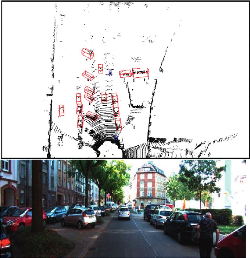
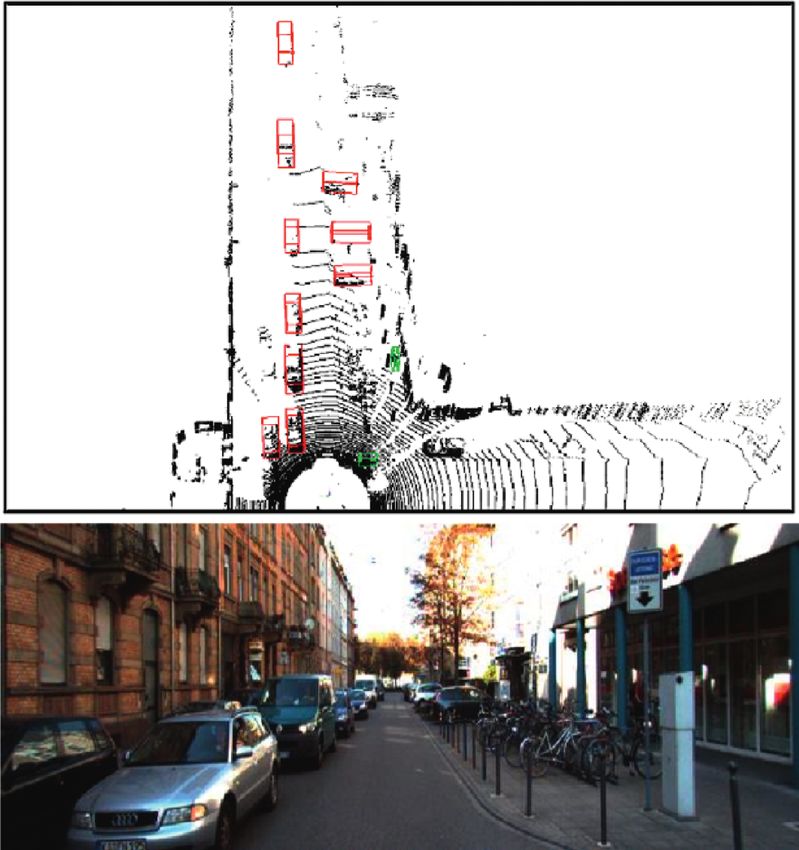
8 Mobile Information Systems

 Figure 7: Detecting result.

angle between 0 and 360 degrees. We compared the influ- References
ence of deformable convolution on 3D object detection
through experiments in Table 1. [1] M. Cho, D. Shin, and J.-J. Lee, “Position detection of a
 Visualization results: the detection result is shown in scattering 3D object by use of the axially distributed image
 sensing technique,” Journal of the Optical Society of Korea,
Figure 7. The above figure shows the visualization results of
 vol. 18, no. 4, pp. 414–418, 2014.
the 3D bounding box of the detection results projected on [2] T. Southey, “Improving object detection using 3D spatial
the aerial view. The following figure shows the road con- relationships,” The EMBO Journal, vol. 19, no. 11, pp. 2558–
ditions in front of the vehicle photographed by the camera. 2568, 2013.
In the aerial view, the red box is a car, the blue box is a [3] M. Ma, F. Guo, Z. Cao, and K. Wang, “Development of an
pedestrian, and the green box is a rider. The algorithm can artificial compound eye system for three-dimensional object
accurately detect the cars, pedestrians, and riders around detection,” Applied Optics, vol. 53, no. 6, pp. 1166–1172,
the vehicle. 2014.
 [4] L. Yan, K. Liu, E. Belyaev, and M. Duan, “RTL3D: real-time
5. Conclusions LIDAR-based 3D object detection with sparse CNN,” IET
 Computer Vision, vol. 14, no. 5, pp. 224–232, 2020.
3D object detection algorithm based on point cloud data [5] J. Chen, Y. Fang, and Y. K. Cho, “Real-time 3D crane
in driverless scene has always been a research hotspot in workspace update using a hybrid visualization approach,”
driverless perception technology. With the development Journal of Computing in Civil Engineering, vol. 31, no. 5,
and maturity of deep neural network technology, the pp. 04017049.1–04017049.15, 2017.
method of 3D target detection using neural network began [6] F. Pomerleau, M. Liu, F. Colas, and R. Siegwart, “Challenging
to show great advantages. Based on the point cloud data data sets for point cloud registration algorithms,” The In-
collected by vehicle 64 line LiDAR and using the Kitti ternational Journal of Robotics Research, vol. 31, no. 14,
dataset as the evaluation sample, this paper studies how to pp. 1705–1711, 2012.
detect the position, size, and direction of obstacles in the [7] R. Girshick, “Fast R-CNN,” in Proceedings of the IEEE In-
environment quickly and accurately based on the point ternational Conference on Computer Vision, pp. 1440–1448,
cloud data, so as to provide reliable information for vehicle Santiago, Chile, December 2015.
 [8] C. R. Qi, W. Liu, C. Wu, H. Su, and L. J. Guibas, “Frustum
tracking and path planning.
 pointnets for 3D object detection from RGB-D data,” 2018,
 https://arxiv.org/abs/1711.08488.
Data Availability [9] Y. Mae, J. Choi, H. Takahashi, K. Ohara, T. Takubo, and
 T. Arai, “Interoperable vision component for object detection
The data used to support the findings of this study are and 3D pose estimation for modularized robot control,”
available from the corresponding author upon reasonable Mechatronics, vol. 21, no. 6, pp. 983–992, 2011.
request. [10] Z. Zhao and X. Chen, “Building 3D semantic maps for mobile
 robots using RGB-D camera,” Intelligent Service Robotics,
Conflicts of Interest vol. 9, no. 4, pp. 1–13, 2016.
 [11] F. Endres, J. Hess, J. Sturm, D. Cremers, and W. Burgard, “3-D
The authors declare that they have no conflicts of mapping with an RGB-D camera,” IEEE Transactions on
interest. Robotics, vol. 30, no. 1, pp. 177–187, 2014.
Mobile Information Systems 9

[12] Y. Furukawa and J. Ponce, “Accurate, dense, and robust [27] S. Shi, X. Wang, and H. Li, “3D object proposal generation and
 multiview stereopsis,” IEEE Transactions on Pattern Analysis detection from point cloud,” 2019, https://arxiv.org/abs/1812.
 and Machine Intelligence, vol. 32, no. 8, pp. 1362–1376, 2010. 04244.
[13] R.-F. Wang, W.-Z. Chen, S.-Y. Zhang, Y. Zhang, and X.-Z. Ye, [28] Y. Yan, Y. Mao, and B. Li, “SECOND: sparsely embedded
 “Similarity-based denoising of point-sampled surfaces,” convolutional detection,” Sensors, vol. 18, no. 10, p. 3337,
 Journal of Zhejiang University—Science, vol. 9, no. 6, 2018.
 pp. 807–815, 2008. [29] Q. Zhu and Z. Mu, “PointNet++ and three layers of features
[14] D. Maturana and S. A. Scherer, “VoxNet: A 3D convolutional fusion for occlusion three-dimensional ear recognition based
 neural network for real-time object recognition,” in Pro- on one sample per person,” Symmetry, vol. 12, no. 1, p. 78,
 ceedings of the IEEE/RSJ International Conference on Intelli- 2020.
 gent Robots and Systems, pp. 922–928, Hamburg, Germany, [30] J. Ashburner and K. J. Friston, “Voxel-based morphometry-
 September 2015. the methods,” NeuroImage, vol. 11, no. 6, pp. 805–821, 2000.
[15] H. Su, S. Maji, and E. Kalogerakis, “Multi-view convolutional [31] D. Z. Wang and I. Posner, “Voting for voting in online point
 neural networks for 3D shape recognition,” in Proceedings of cloud object detection,” in Proceedings of the Robotics: Science
 the IEEE International Conference on Computer Vision, and Systems XI, Rome, Italy, March 2015.
 pp. 945–953, Santiago, Chile, December 2015. [32] B. Li, “3D fully convolutional network for vehicle detection in
[16] C. Premebida, J. Carreira, J. Batista, and U. Nunes, “Pedes- point cloud,” in Proceedings of the 2017 IEEE/RSJ Interna-
 trian detection combining RGB and dense LIDAR data,” in tional Conference on Intelligent Robots and Systems, IROS,
 pp. 1513–1518, Vancouver, BC, Canada, September 2017.
 Proceedings of the 2014 IEEE/RSJ International Conference on
 [33] S. Song and J. Xiao, “Sliding shapes for 3D object detection in
 Intelligent Robots and Systems, pp. 4112–4117, Chicago, IL,
 depth images,” in Computer Vision—ECCV 2014—13th Eu-
 USA, September 2014.
 ropean Conference, pp. 634–651, Springer, Berlin, Germany,
[17] M. Enzweiler and D. M. Gavrila, “A multilevel mixture-of-
 2014.
 experts framework for pedestrian classification,” IEEE
 [34] C. R. Qi, L. Yi, H. Su, and L. J. Guibas, “PointNet++: deep
 Transactions on Image Processing, vol. 20, no. 10, pp. 2967– hierarchical feature learning on point sets in a metric space,”
 2979, 2011. in Proceedings of the Annual Conference on Neural Infor-
[18] A. S. Mian, M. Bennamoun, and R. A. Owens, “On the re- mation Processing Systems, pp. 5099–5108, Long Beach, CA,
 peatability and quality of keypoints for local feature-based 3D USA, June 2017.
 object retrieval from cluttered scenes,” International Journal
 of Computer Vision, vol. 89, no. 2, pp. 348–361, 2011.
[19] P. Bariya and K. Nishino, “Scale-hierarchical 3D object rec-
 ognition in cluttered scenes,” in Proceedings of the Twenty-
 Third IEEE Conference on Computer Vision and Pattern
 Recognition, pp. 1657–1664, San Francisco, CA, USA, June
 2010.
[20] S. Song and J. Xiao, “Deep sliding shapes for amodal 3D object
 detection in RGB-D images,” in Proceedings of the IEEE
 Conference on Computer Vision and Pattern Recognition,
 pp. 808–816, Las Vegas, NV, USA, June 2016.
[21] S. Ren, K. He, R. Girshick, and J. Sun, “Faster R-CNN: towards
 real-time object detection with region proposal networks,”
 IEEE Transactions on Pattern Analysis and Machine Intelli-
 gence, vol. 39, no. 6, pp. 1137–1149, 2017.
[22] S. Du, B. Liu, Y. Liu, and J. Liu, “Global-local articulation
 pattern-based pedestrian detection using 3D lidar data,”
 Remote Sensing Letters, vol. 7, no. 7, pp. 681–690, 2016.
[23] H. Kuang, B. Wang, J. An, M. Zhang, and Z. Zhang, “Voxel-
 FPN: multi-scale voxel feature aggregation for 3D object
 detection from LIDAR point clouds,” Sensors, vol. 20, no. 3,
 p. 704, 2020.
[24] S. Qie and J. Cheng, S. Wang, C. Xu, and G. Xiangyang,
 “Point-selection and multi-level-point-feature fusion-based
 3d point cloud classification,” Electronics Letters, vol. 56, no. 6,
 pp. 290–293, 2020.
[25] A. Dai, A. X. Chang, M. Savva, M. Halber, T. A. Funkhouser,
 and M. Nießner, “ScanNet richly-annotated 3D reconstruc-
 tions of in-door scenes,” in Proceedings of the IEEE Conference
 on Computer Vision and Pattern Recognition, pp. 2432–2443,
 Honolulu, HI, USA, July 2017.
[26] Y. Xiang, W. Choi, Y. Lin, and S. Savarese, “Asymmetric
 fingerprinting based on 1-out-of-n oblivious transfer,” in
 Proceedings of the IEEE Conference on Computer Vision and
 Pattern Recognition, pp. 1903–1911, Boston, MA, USA, June
 2015.
You can also read