Logical-qubit operations in an error-detecting surface code
←
→
Page content transcription
If your browser does not render page correctly, please read the page content below
Logical-qubit operations in an error-detecting surface code

 J. F. Marques,1, 2 B. M. Varbanov,1 M. S. Moreira,1, 2 H. Ali,1, 2 N. Muthusubramanian,1, 2 C. Zachariadis,1, 2
F. Battistel,1 M. Beekman,1, 3 N. Haider,1, 3 W. Vlothuizen,1, 3 A. Bruno,1, 2 B. M. Terhal,1, 4 and L. DiCarlo1, 2, ⇤
              1
               QuTech, Delft University of Technology, P.O. Box 5046, 2600 GA Delft, The Netherlands
                            2
                              Kavli Institute of Nanoscience, Delft University of Technology,
                                    P.O. Box 5046, 2600 GA Delft, The Netherlands
                          3
                            Netherlands Organisation for Applied Scientific Research (TNO),
                                P.O. Box 96864, 2509 JG The Hague, The Netherlands
          4
            JARA Institute for Quantum Information, Forschungszentrum Juelich, D-52425 Juelich, Germany
                                                 (Dated: March 20, 2021)
              Future fault-tolerant quantum computers will require storing and processing quantum data in
           logical qubits. We realize a suite of logical operations on a distance-two logical qubit stabilized
           using repeated error detection cycles. Logical operations include initialization into arbitrary states,
           measurement in the cardinal bases of the Bloch sphere, and a universal set of single-qubit gates.
           For each type of operation, we observe higher performance for fault-tolerant variants over non-fault-
           tolerant variants, and quantify the difference through detailed characterization. In particular, we
           demonstrate process tomography of logical gates, using the notion of a logical Pauli transfer matrix.
           This integration of high-fidelity logical operations with a scalable scheme for repeated stabilization
           is a milestone on the road to quantum error correction with higher-distance superconducting surface
           codes.

                  INTRODUCTION                                  However, except for smaller-scale experiments using two
                                                                ion species [12], trapped-ion experiments in QEC have
   Two key capabilities will distinguish an error-              so far been limited to a single round of stabilization.
corrected quantum computer from present-day noisy                 In parallel, taking advantage of highly-non-
intermediate-scale quantum (NISQ) processors [1].               demolition measurement in circuit quantum elec-
First, it will initialize, transform, and measure quan-         trodynamics [13], superconducting circuits have taken
tum information encoded in logical qubits rather than           key strides in repetitive stabilization of two-qubit
physical qubits. A logical qubit is a highly entangled          entanglement [14, 15] and logical qubits.        Quan-
two-dimensional subspace in the larger Hilbert space of         tum memories based on 3D-cavity logical qubits
many more physical qubits. Second, it will use repet-           in cat [16, 17] and Gottesman-Kitaev-Preskill [18]
itive quantum parity checks to discretize, signal, and          codes have crossed the memory break-even point.
(with aid of a decoder) correct errors occurring in the         Meanwhile, monolithic architectures have focused on
constituent physical qubits without destroying the en-          logical qubit stabilization in a surface code realized
coded information [2]. Provided the incidence of phys-          with a 2D lattice of transmon qubits. Currently, the
ical errors is below a code-specific threshold and the          surface code [19] is the most attractive QEC code
quantum circuits for logical operations and stabiliza-          for solid-state implementation owing to its practical
tion are fault-tolerant, the logical error rate can be ex-      nearest-neighbor connectivity requirement and high
ponentially suppressed by increasing the distance (re-          error threshold.    Recent experiments [5, 20] have
dundancy) of the quantum error correction (QEC) code            demonstrated repetitive stabilization by post-selection
employed [3]. At present, the exponential suppression           in a surface code which, owing to its small size, is
for specific physical qubit errors (bit-flip or phase-flip)     capable of quantum error detection but not correction.
has been experimentaly demonstrated [4, 5] for repeti-             We demonstrate a complete suite of logical-qubit op-
tion codes [6–8].                                               erations for this small (distance-2) surface code while
   Leading experimental quantum platforms have taken            preserving multi-round stabilization. Our logical oper-
key steps towards implementing QEC codes protect-               ations span initialization anywhere on the logical Bloch
ing logical qubits from general physical qubit errors.          sphere, measurement in all cardinal bases, and a uni-
In particular, trapped-ion systems have demonstrated            versal set of single-logical-qubit gates. For each type
logical-level initialization, gates and measurements for        of operation, we quantify the increased performance of
single logical qubits in the Calderbank-Shor-Steane [9]         fault-tolerant variants over non-fault-tolerant ones. We
and Bacon-Shor [10] codes. Most recently, entangling            introduce the notion of a logical Pauli transfer matrix
operations between two logical qubits have been demon-          to describe a logical gate, analogous to the procedure
strated in the surface code using lattice surgery [11].         commonly used to describe gates on physical qubits [21].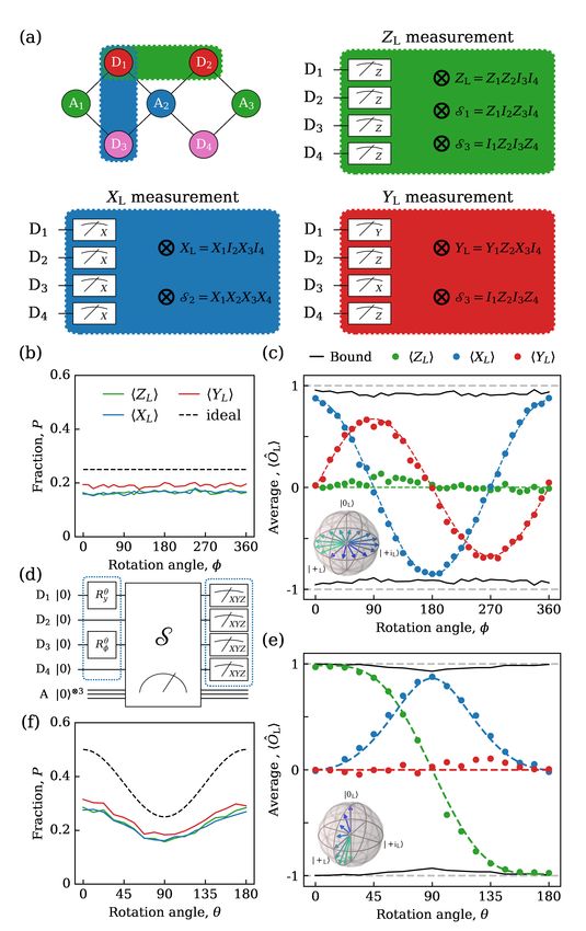
2
Finally, we compare the performance of two scalable,
fault-tolerant stabilizer measurement schemes compat-
ible with our quantum hardware architecture [22].
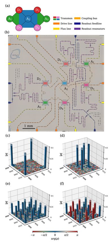
The distance-2 surface code (Fig. 1a) uses four data
qubits (D1 through D4 ) to encode one logical qubit,
whose two-dimensional codespace is the even-parity
(i.e., eigenvalue +1) subspace of the stabilizer set
S = {ZD1 ZD3 , XD1 XD2 XD3 XD4 , ZD2 ZD4 }. (1)
This codespace has logical Pauli operators
ZL = ZD1 ZD2 , ZD3 ZD4 , ZD1 ZD4 , and ZD2 ZD3 , (2)
XL = XD1 XD3 and XD2 XD4 , (3)
that anti-commute with each other and commute with
S, and logical computational basis
1
|0L i = p (|0000i + |1111i) , (4)
2
1
|1L i = p (|0101i + |1010i) . (5)
2
Measuring the stabilizers using three ancilla qubits (A1 ,
A2 and A3 in Fig. 1a) allows detection of all individual
physical-qubit errors. Such errors change the outcome
of one or more stabilizers to m = 1. However, no error
syndrome combination is unique to a single error. For
instance, a phase flip in any one data qubit triggers the
same syndrome: mA2 = 1. Consequently, this code
cannot be used to correct such errors. We thus perform
state stabilization by post-selecting runs in which no
error is detected by the stabilizer measurements in any
cycle. In this error-detection context, an operation is
fault-tolerant if any single-fault produces a non-trivial
syndrome and can therefore be post-selected out [23].
RESULTS
Stabilizer measurements
Achieving high performance in a code hinges on per-
forming projective quantum parity (stabilizer) measure- Figure 1. Surface-7 quantum processor and initial-
ments with high assignment fidelity and low additional ization of logical cardinal states. (a) Distance-two sur-
backaction. We implement each of the stabilizers in S face code. (b) Optical image of the quantum hardware with
added false-color to emphasize different circuit elements. (c-
using a standard indirect-measurement scheme [24, 25] f) Estimated physical density matrices, ⇢, after targeting the
with a dedicated ancilla. As a fidelity metric, we mea- preparation of the logical cardinal states |0L i (c), |1L i (d),
sure the average probability to correctly assign the par- |+L i (e) and | L i (f). Each state is measured after prepar-
ity ZD1 ZD3 , ZD1 ZD2 ZD3 ZD4 and ZD1 ZD3 of physical ing the data qubits in |0000i, |1010i, |++++i and |++ i,
computational states of the data-qubit register, finding respectively. The ideal target state density matrix is shown
94.2%, 86.1% and 97.2%, respectively (see Fig. S2). in the shaded wireframe.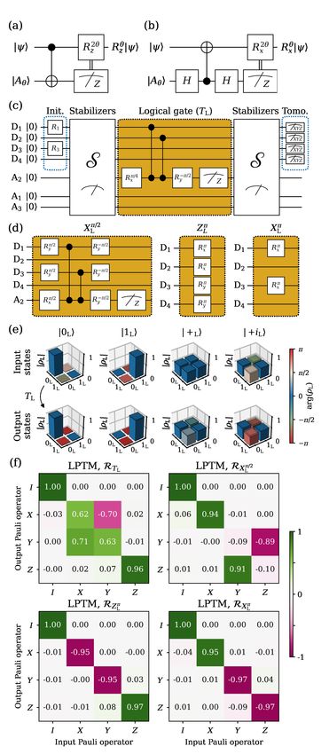
3

     Logical state initialization using stabilizer
                    measurements

   A practical means to quantify the backaction of sta-
bilizer measurements is using them to initialize logical
states. As proposed in Ref. 20, we can prepare arbitrary
logical states by first initializing the data-qubit register
in the product state

 | i = C✓/2 |0i + S✓/2 |1i |0i C✓/2 |0i + S✓/2 ei |1i |0i
                                                     (6)
using single-qubit rotations Ry✓ on D1 and R✓ on D3
acting on |0000i (C↵ = cos ↵ and S↵ = sin ↵). A follow-
up round of stabilizer measurements ideally projects the
four-qubit state onto the logical state
           ⇣                          ⌘ q
              2           2
   | L i = C✓/2  |0L i + S✓/2 ei |1L i / C✓/2
                                           4 + S4
                                                   ✓/2
                                                         (7)
with probability
                         1⇣ 4      4
                                       ⌘
                   P =     C✓/2 + S✓/2   .               (8)
                         2
We use this procedure to target initialization of the log-p
ical cardinal states |0L i, |1L i, |+L i = |0L i + |1L i / 2,
                               p
and | L i = |0L i |1L i / 2. For the first two states,
the procedure is fault-tolerant according to the defini-
tion above. We characterize the produced states us-
ing full four-qubit state tomography including readout
calibration and maximum-likelihood estimation (MLE)
(Fig. 1c-f). The fidelity F4Q to the ideal four-qubit tar-
get states is 90.0 ± 0.3%, 92.9 ± 0.2%, 77.3 ± 0.5%, and
77.1±0.5%, respectively. For each state, we can extract
a logical fidelity FL by further projecting the obtained
four-qubit density matrix onto the codespace [20], find-        Figure 2. Arbitrary logical-state initialization and
ing 99.83 ± 0.08%, 99.97 ± 0.04%, 96.82 ± 0.55%, and            measurement in the logical cardinal bases. (a) As-
                                                                sembly of data-qubit measurements used to evaluate logical
95.54 ± 0.55%, respectively (see Methods). This sharp
                                                                operators ZL , XL and YL with additional error detection.
increase from F4Q to FL demonstrates that the vast              (d) Initialization of logical states using the procedure de-
majority of errors introduced by the parity check are           scribed in Eq. 6. (c, e) ZL , XL and YL logical measurement
weight-1 and detectable. A simple modification makes            results as a function of the gate angles (c) and ✓ (e). The
the initialization of |+L i (| L i) also fault-tolerant: ini-   colored dashed curves show a fit of the analytical prediction
tialize the data-qubit register in a different product           based on Eqs. 9 and 11 to the data and the dark curve de-
state, namely |++++i (|++              i), before performing    notes a bound based on the measured FL of each state. (b,
                                                                f) Total fraction P of post-selected data as a function of the
the stabilizer measurements. With this modification,
                                                                input angle for each logical measurement. The dashed curve
F4Q increases to 85.4 ± 0.3% (84.6 ± 0.3%) and FL to            shows the ideal fraction given by Eq. 8.
99.78 ± 0.09% (99.64 ± 0.17%), matching the perfor-
mance achieved when targetting |0L i and |1L i.

                                                                simultaneously measuring all data qubits in the X (Z)
      Logical measurement of arbitrary states                   basis to obtain a string of data-qubit outcomes (each
                                                                +1 or 1). The value assigned to the logical oper-
  A key feature of a code is the ability to measure             ator is the computed product of data-qubit outcomes
logical operators. In the surface code, we can mea-             as prescribed by Eq. 3 (2). Additionally, the outcome
sure XL (ZL ) fault-tolerantly, albeit destructively, by        string is used to compute a value for the stabilizer(s)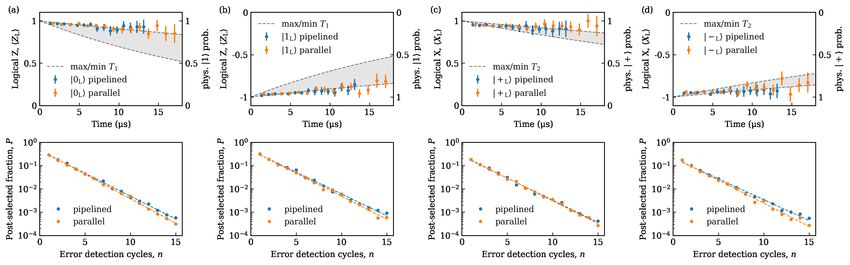
4

XD1 XD2 XD3 XD4 (ZD1 ZD3 and ZD2 ZD4 ), enabling a
final step of error detection (Fig. 2a). Measurement
of YL = +iXL ZL = YD1 ZD2 XD3 is not fault-tolerant.
However, we lower the logical assignment error by also
measuring D4 in the Z basis to compute a value for
ZD2 ZD4 and thereby detect bit-flip errors in D2 and
D4 .
   We demonstrate ZL , XL and YL measurements on
logical states prepared on two orthogonal planes of the
logical Bloch sphere. Setting ✓ = ⇡/2 and sweeping ,
we ideally prepare logical states on the equator (Fig. 2d)
                                          p
              | L i = |0L i + ei |1L i / 2.            (9)

We measure the produced states in the ZL , XL and YL
bases and obtain experimental averages hZL i, hXL i and
hYL i. As expected, we observe sinusoidal oscillations in
hXL i and hYL i and near-zero hZL i. We extract logical
assignment fidelities FLR for XL and YL from hXL i and
hYL i at the cardinal states accounting for initialization
error given by FL :

    (2FLR   1)(2FL   1) = max|hOL i| , O 2 {X, Y }. (10)

We find FLR = 95.8% for XL and 87.5% for YL , which
manifests the non-fault-tolerant nature of YL measure-
ment. A second manifestation is the higher fraction P
of post-selected data in this case (Fig. 2b).
   Setting = 0 and sweeping ✓, we then prepare logical
states on the XL -ZL plane of the logical Bloch sphere
(Fig. 2e), ideally
          ⇣                        ⌘ q
             2            2              4 + S 4 . (11)
  | L i = C✓/2   |0L i + S✓/2 |1L i / C✓/2    ✓/2

Note that due to the changing overlap of the initial
product state with the codespace, P is now a function
of ✓ (Eq. 8). Using the same procedure as above, we ex-
tract FLR = 99.4% for ZL and 96.4% for XL . Although
both measurements are fault-tolerant, FLR is higher for
ZL . This arises because the ZL measurement is only
vulnerable to vertical double bit-flip errors while the
XL measurement is vulnerable to horizontal and diago-
nal double phase-flip errors.                                Figure 3. Logical gates and their characterization. (a,
                                                             b) General gate-by-measurement schemes realizing arbitrary
                                                             rotations around the Z (a) and X (b) axis of the Bloch
                      Logical gates                          sphere. (c) Process tomography experiment of the TL gate.
                                                             Input cardinal logical states are initialized using the method
                                                             of Fig. 2. Output states are measured following a second
   Finally, we demonstrate a suite of gates enabling uni-                                                           ⇡/2
                                                             round of stabilizer measurements. (d) Logical XL , ZL⇡
versal logical-qubit control (Fig. 3). Full control of
                                                             and XL gates compiled using our hardware-native gateset.
                                                                    ⇡
the logical qubit requires a gate set comprising Clif-       (e) Logical state tomography of input and output states of
ford and non-Clifford logical gates. Some Clifford gates,      the TL gate. These logical density matrices are obtained by
like ZL⇡ and XL⇡ , can be implemented transversally and      performing four-qubit tomography of the data qubits and
therefore fault-tolerantly (Fig. 3d). We perform arbi-       then projecting onto the codespace. (f) Extracted logical
trary rotations (generally non-fault-tolerant) about the     Pauli transfer matrices.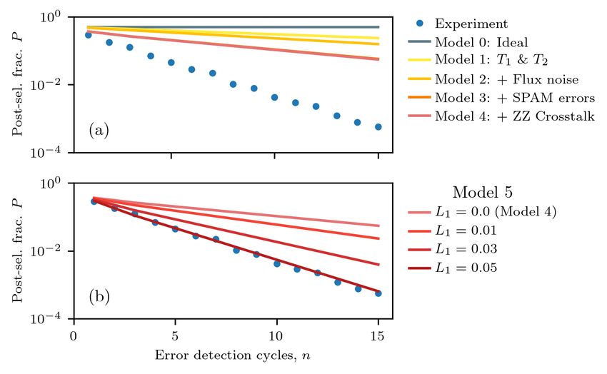
5

Figure 4. Repetitive error detection using pipelined and parallel stabilizer measurement schemes. (a, b) Gate
sequences used to implement the pipelined (a) and parallel (b) stabilizer measurement schemes. Gate duration is 20 ns
for single-qubit gates, 60 ns for controlled-Z (CZ) gates and parking [14, 22], and 540 ns for ancilla readout. The order
of CZs in the XD1 XD2 XD3 XD4 stabilizer (blue shaded region) prevents the propagation of ancilla errors into logical qubit
errors [23]. The total cycle duration for the pipelined (parallel) scheme is 840 ns (1000 ns). (c) Estimated ZL expectation
value, hZL i, measured for the |0L i state versus the duration of the experiment using the pipelined (blue) and the parallel
(orange) schemes. We also plot the excited-state probability (right axis) set by the maximum and minimum physical qubit
T1 . (d) Post-selected fraction of data versus the number of error detection cycles n for the pipelined (blue) and parallel
(orange) scheme.

ZL axis using the standard gate-by-measurement cir-                   Pipelined versus parallel stabilizer measurements
cuit [26] shown in Fig. 3a. In our case, the ancilla
is physical (A2 ), while the qubit transformed is our                   A scalable control scheme is fundamental to realize
logical qubit. The rotation angle ✓ is set          p by the ini-    surface codes with large code distance. To this end,
tial ancilla state |A✓ i = (|0i + ei✓ |1i)/ 2. Since we              we now compare the performance of two schemes suit-
cannot do binary-controlled ZL rotations, we simply                  able for the quantum hardware architecture proposed
post-select runs in which the measurement outcome is                 in Ref. 22. These schemes are scalable in the sense
mA2 = +1. Choosing ✓ = ⇡/4 implements the non-                       that their cycle duration remains independent of code
                       ⇡/4
Clifford TL = ZL gate. A similar circuit (Fig. 3b)                    distance. The pipelined scheme interleaves the coher-
can be used to perform arbitrary rotations around the                ent operations and ancilla readout steps associated with
XL axis. We compile both circuits using our hardware-                stabilizer measurements of type X and Z by perform-
native gateset (Figs. 3c,d). To assess logical-gate per-             ing the coherent operations of X (Z) type stabilizers
formance, we perform logical process tomography us-                  during the readout of Z (X) type stabilizers (Fig. 4a).
ing the procedure illustrated in Fig. 3e for TL . First,             The parallel scheme performs all ancilla readouts simul-
we initialize into each of the six logical cardinal states           taneously (Fig. 4b). To compare their performance, we
{|0L i , |1L i , |+L i , | L i , |+iL i , | iL i}. We characterize   initialize and stabilize |0L i for up to n = 15 cycles.
each actual input state by four-qubit state tomography               We separately calibrate the equatorial rotation axis of
and project to the codespace to obtain a logical density             refocusing pulses (R' ⇡
                                                                                             i
                                                                                               ) in each scheme to extract the
matrix. Next, we similarly characterize each output                  best performance in both schemes. At each n, we take
state produced by the logical gate and a second round                data back-to-back for the two schemes in order to min-
of stabilizer measurements to detect errors occurred in              imize the effect of parameter drift, repeating each ex-
the gate. Using this over-complete set of input-output               periment up to 256 ⇥ 103 times. Figure 4c shows the ZL
logical-state pairs, combined with MLE (see Methods),                measurement outcome averaged over the post-selected
we extract a logical Pauli transfer matrix (LPTM). The               runs. We extract the error-detection rate from the
                                                               ⇡/2
resulting LPTMs for the non-fault-tolerant TL and XL                 n-dependence of the fraction of post-selected data P
gates as well as the fault-tolerant ZL and XL are shown
                                               ⇡      ⇡              (Fig. 4d) using the procedure described in Methods.
in Fig. 3e. From the LPTMs, we extract average logical               We observe that the error rate is slightly lower for the
gate fidelities FLG (Eq. 19) 97.3%, 95.6%, 97.9%, and                pipelined scheme ( pip ⇠ 45%), most likely due to the
98.1%, respectively.                                                 shorter duration of the cycle. This superiority is con-
                                                                     sistent across different input logical states (see Fig. S3)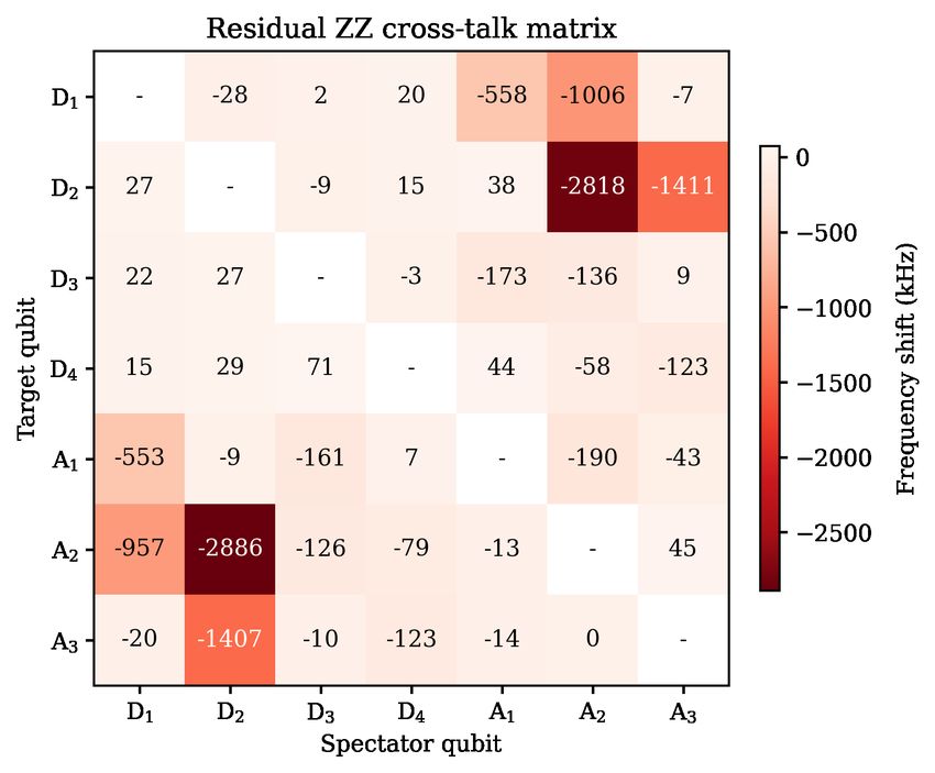
6

with an average ratio   pip / par   ⇠ 97%.                     Logical operation Characteristic Logical fidelity metric value (%)
                                                                       |0L i         FT                                  99.83
                                                                                     FT                                  99.97

                                                              Init.
                                                                       |1L i                               FL
                                                                      |+L i      Non-FT/FT                            96.82/99.78
                     DISCUSSION
                                                                      | Li       Non-FT/FT                            95.54/99.64
                                                                        ZL           FT                                   99.4

                                                              Meas.
   We have demonstrated a suite of logical-level initial-               XL           FT                    FLR           96.0⇤
ization, gate and measurement operations in a distance-                 YL        Non-FT                                  87.5
2 superconducting surface code undergoing repetitive                    ZL⇡          FT                                   98.1
stabilizer measurements. For each type of logical oper-

                                                              Gate
                                                                       XL⇡           FT                    FLG            97.9
                                                                         ⇡/2
ation, we have quantified the increased performance of                XL          Non-FT                                  95.6
                                                                        TL        Non-FT                                  97.3
fault-tolerant variants over non-fault-tolerant variants.
Table I summarizes all the results. We can initialize the     Table I. Summary of logical initialization, measure-
logical qubit to any point on the logical Bloch sphere,       ment, and gate operations and their performance.
with logical fidelity surpassing Ref. 20. In addition to      Fault-tolerant operations are labelled FT and non-fault tol-
characterizing initialized states using full four-qubit to-   erant ones Non-FT. ⇤ Weighted average of values extracted
mography, we also demonstrate logical measurements            from Figs. 2c,e.
in all logical cardinal bases. Finally, we demonstrate a
universal single-qubit set of logical gates by performing
                                                              proposed in Ref. 22. We employ flux-tunable transmons
logical process tomography, introducing the concept of
                                                              arranged in three frequency groups: a high-frequency
a logical-level Pauli transfer matrix.
                                                              group for D1 and D2 ; a middle-frequency group for A1 ,
   With a view towards implementing higher-distance
                                                              A2 and A3 ; and a low-frequency group for D3 and D4 .
surface codes using our quantum-hardware architec-
                                                              Each transmon is transversely coupled to its nearest
ture [22], we have compared the performance of two
                                                              neighbor using a dedicated coupling bus resonator and
scalable stabilization schemes: the pipelined and paral-
                                                              features an individual microwave drive line for single-
lel measurement schemes. In this comparison, two main
                                                              qubit gates, a flux line for two-qubit gates, and a disper-
factors compete. On one hand, the shorter cycle time fa-
                                                              sively coupled readout resonator with Purcell filter for
vors pipelining. On the other, the pipelining introduces
                                                              readout [15, 30]. All transmons are flux biased to their
extra dephasing on ancilla qubits of one type during
                                                              maximal frequency (i.e., flux sweetspot [31]). Qubit re-
readout of the other. The performance of both schemes
                                                              laxation (T1 ) and dephasing (T2 ) times lie in the range
is comparable, but slightly higher for the pipelined
                                                              27—102 µs and 55—117 µs, respectively. Detailed in-
scheme. From density-matrix simulations discussed in
                                                              formation on the implementation and performance of
detail in the Supplementary Material, we further un-
                                                              single- and two-qubit gates can be found in Ref. 32.
derstand that conventional qubit errors such as en-
                                                              Device characteristics are also summarized in Table S1.
ergy relaxation, dephasing and readout assignment er-
ror alone do not account for the net error-detection rate
observed in the experiment (Fig. S5). We believe that                               State tomography
the dominant error source is instead leakage to higher
transmon states incurred during CZ gates. Our data              To perform state tomography on the prepared logical
(Fig. S4) shows that the error detection scheme suc-          states, we measure the 44 1 expectation values of data-
cessfully post-selects leakage errors in both the ancilla     qubit Pauli observables, pi = h i i, i 2 {I, X, Y, Z}⌦4
and data qubits. Learning to identify these non-qubit         (except I ⌦4 ). These are used to construct the density
errors and to correct them without post-selection is the      matrix
subject of ongoing research [27–29] and an outstanding
challenge in the quest for quantum fault-tolerance with                                       4
                                                                                             4X 1
                                                                                                    pi i
higher-distance superconducting surface codes.                                         ⇢=                                     (12)
                                                                                              i=0
                                                                                                     24

                                                              with p0 = 1, corresponding to 0 = I ⌦4 . Due to
                      METHODS                                 statistical uncertainty in the measurement, the con-
                                                              structed state, ⇢, might lack the physicality charac-
                         Device                               teristic of a density matrix, that is, Tr(⇢) = 1 and
                                                              ⇢      0. Specifically, ⇢ might not satisfy the latter
  We use a seven-transmon superconduting processor            constraint, while the former is automatically satisfied
(Fig. 1b) featuring the quantum-hardware architecture         by p0 = 1. To enforce these constraints, we use a
7
maximum-likelihood method [21] to find the physical where the first tensor-product factor corresponds to
density matrix, ⇢ph , that is closest to the measured an auxiliary subsystem. The TPCP constraints are
state, where closeness is defined in terms of best match- Tr(⇢R R
ph ) = 1, ⇢ph 0 and Tr1 (⇢R
ph ) = 1/2, where Tr1 is
ing the measurement results. We thus minimize the cost the partial trace over the auxiliary subsystem. In other
P 44 1
function i=0 |pi Tr(⇢ph i )|2 , subject to Tr(⇢ph ) = 1 words, ⇢R ph is a density matrix satisfying an extra con-
and ⇢ph 0. We find the optimal ⇢opt ph using the convex-
straint. We then find the optimal ⇢R,opt
ph using the same
optimization package cvxpy via cvx-fit in Qiskit [33]. convex-optimization methods as for state tomography
The fidelity to a target pure state, | i, is then com- and adding this extra constraint [21, 34]. We compute
puted as the corresponding LPTM via
F = h | ⇢opt
ph | i . (13) (Ropt R,opt
ph )ij = Tr(⇢ph
T
j ⌦ i ). (18)
One can further project ⇢ph onto the codespace to ob- and the average logical gate fidelity using
tain a logical state ⇢L using
1 X Tr(⇢ph iL ) L Tr(R†ideal Ropt
ph ) + 2
⇢L = , iL 2 {IL , XL , YL , ZL } (14) FLG = , (19)
2 i Tr(⇢ph IL ) i 6
where Rideal is the LPTM of the ideal target gate.
where IL is the projector onto the codespace. Here, we
can compute the logical fidelity FL using Eq. 13.
Extraction of error-detection rate
Process tomography in the codespace
The fraction of post-selected data P in the repetitive
error detection experiment (Fig. 4b) decays exponen-
A general single-qubit gate can be described [21] by
tially with the number of cycles n. This is consistent
a Pauli transfer matrix (PTM) R that maps an in-
with a constant error-detection rate per cycle . We
put state described by pi = h i i, i 2 {I, X, Y, Z}, with
extract this rate by fitting the function
p0 = 1, to an output state p0 :
X P (n) = A(1 )n . (20)
p0j = Rij pi . (15)
i
To construct R in the codespace, we
use an overcomplete set of input states,
{|0L i , |1L i , |+L i , | L i , |+iL i , | iL i}, and their corre- ⇤
Corresponding author: L.dicarlo@tudelft.nl
sponding output states and perform linear inversion.
[1] Preskill, J. Quantum Computing in the NISQ era and
The input and output logical states are characterized beyond. Quantum 2, 79 (2018).
using state tomography of the data qubits to find [2] Terhal, B. M. Quantum error correction for quantum
the four-qubit state ⇢, which is then projected to the memories. Rev. Mod. Phys. 87, 307–346 (2015)
codespace using: [3] Martinis, J. M. Qubit metrology for building a fault-
tolerant quantum computer. npj Quantum Inf. 1, 15005
Tr(⇢ iL ) (2015).
pLi = , L
i 2 {IL , XL , YL , ZL }, (16)
Tr(⇢IL ) [4] Kelly, J. et al. State preservation by repetitive error
detection in a superconducting quantum circuit. Nature
We find that all the measured logical states already sat-
519, 66–69 (2015).
isfy the constraints of a physical density matrix. This [5] Chen, Z. et al. Exponential suppression of bit or phase
is likely to happen as one-qubit states that are not very flip errors with repetitive error correction. Preprint at
pure usually lie within the Bloch sphere even within http://arXiv.org/abs/2102.06132 (2021).
the uncertainty in the measurement. The constructed [6] Ristè, D. et al. Detecting bit-flip errors in a logical qubit
LPTM, however, might not satisfy the constraints of a using stabilizer measurements. Nat. Commun. 6, 6983
physical quantum channel, that is, trace preservation (2015).
[7] Cramer, J. et al. Repeated quantum error correction on
and complete positivity (TPCP). These are better ex-
a continuously encoded qubit by real-time feedback. Nat.
pressed by switching from the PTM representation to Commun. 5, 11526 (2016).
the Choi representation. The Choi state ⇢R can be [8] Ristè, D. et al. Real-time processing of stabilizer mea-
computed as surements in a bit-flip code. npj Quantum Information
1X 6, 71 (2020).
⇢R = Rij jT ⌦ i , (17) [9] Nigg, D. et al. Quantum computations on a topologically
4 i,j encoded qubit. Science 345, 302–305 (2014).8
[10] Egan, L. et al. Fault-tolerant operation of qubits. Preprint at http://arXiv.org/abs/2102.08336
a quantum error-correction code. Preprint at (2021).
http://arXiv.org/abs/2009.11482 (2021). [30] Heinsoo, J. et al. Rapid high-fidelity multiplexed read-
[11] Erhard, A. et al. Entangling logical qubits with lattice out of superconducting qubits. Phys. Rev. App. 10,
surgery. Nature 589, 220–224 (2021). 034040 (2018).
[12] Negnevitsky, V. et al. Repeated multi-qubit readout [31] Schreier, J. A. et al. Suppressing charge noise decoher-
and feedback with a mixed-species trapped-ion register. ence in superconducting charge qubits. Phys. Rev. B
Nature 563, 527–531 (2018). 77, 180502(R) (2008).
[13] Blais, A., Huang, R.-S., Wallraff, A., Girvin, S. M. & [32] Negîrneac, V. et al. High-fidelity controlled-z gate with
Schoelkopf, R. J. Cavity quantum electrodynamics for maximal intermediate leakage operating at the speed
superconducting electrical circuits: An architecture for limit in a superconducting quantum processor. Preprint
quantum computation. Phys. Rev. A 69, 062320 (2004). at http://arXiv.org/abs/2008.07411 (2020).
[14] Andersen, C. K. et al. Entanglement stabilization using [33] Qiskit: An open-source framework for quantum com-
ancilla-based parity detection and real-time feedback in puting (2019).
superconducting circuits. npj Quantum Information 5, [34] de Jong, J. Implementation of a fault-tolerant SWAP
1–7 (2019). operation on the IBM 5-qubit device. Master’s thesis,
[15] Bultink, C. C. et al. Protecting quantum entanglement Delft University of Technology (2019).
from leakage and qubit errors via repetitive parity mea-
surements. Science Advances 6 (2020).
[16] Ofek, N. et al. Extending the lifetime of a quantum
ACKNOWLEDGEMENTS
bit with error correction in superconducting circuits.
Nature 536, 441 (2016).
[17] Hu, L. et al. Quantum error correction and universal We thank R. Sagastizabal, M. Sarsby and
gate set operation on a binomial bosonic logical qubit. T. Stavenga for experimental assistance, and G. Calu-
Nat. Phys. (2019). sine and W. Oliver for providing the traveling-wave
[18] Campagne-Ibarcq, P. et al. Quantum error correction
parametric amplifiers used in the readout amplification
of a qubit encoded in grid states of an oscillator. Nature
584, 368–372 (2020). chain. This research is supported by the Office of the
[19] Fowler, A. G., Mariantoni, M., Martinis, J. M. & Cle- Director of National Intelligence (ODNI), Intelligence
land, A. N. Surface codes: Towards practical large-scale Advanced Research Projects Activity (IARPA), via
quantum computation. Phys. Rev. A 86, 032324 (2012). the U.S. Army Research Office Grant No. W911NF-
[20] Andersen, C. K. et al. Repeated quantum error detec- 16-1-0071, and by Intel Corporation. The views and
tion in a surface code. Nat. Phys. 16, 875–880. conclusions contained herein are those of the authors
[21] Chow, J. M. et al. Universal quantum gate set ap-
and should not be interpreted as necessarily repre-
proaching fault-tolerant thresholds with superconduct-
ing qubits. Phys. Rev. Lett. 109, 060501 (2012). senting the official policies or endorsements, either
[22] Versluis, R. et al. Scalable quantum circuit and control expressed or implied, of the ODNI, IARPA, or the
for a superconducting surface code. Phys. Rev. App. 8, U.S. Government. B. M. V., F. B. and B. M. T. are
034021 (2017). supported by ERC Grant EQEC No. 682726.
[23] Tomita, Y. & Svore, K. M. Low-distance surface codes
under realistic quantum noise. Phys. Rev. A 90, 062320
(2014). AUTHOR CONTRIBUTIONS
[24] Saira, O.-P. et al. Entanglement genesis by ancilla-
based parity measurement in 2D circuit QED. Phys.
Rev. Lett. 112, 070502 (2014). J. F. M. performed the experiment and data analysis.
[25] Takita, M. et al. Demonstration of weight-four parity M. B., N. H. and L. D. C. designed the device. N. M.,
measurements in the surface code architecture. Phys. C. Z. and A. B. fabricated the device. J. F. M. and H. A.
Rev. Lett. 117, 210505 (2016). calibrated the device. M. S. M. and W. V. designed the
[26] Aliferis, P., Gottesman, D. & Preskill, J. Quantum
control electronics. B. M. V. performed the numerical
accuracy threshold for concatenated distance-3 codes.
Quantum Inf. Comput. 6, 97–165 (2005). simulations and F. B. implemented the MLE method.
[27] Varbanov, B. M. et al. Leakage detection for a B. M. T. supervised the theory work. J. F. M. and
transmon-based surface code. npj Quantum Informa- L. D. C. wrote the manuscript with contributions from
tion 6, 102 (2020). B. M. V., F. B. and B. M. T., and feedback from all
[28] McEwen, M. et al. Removing leakage-induced cor- coauthors. L. D. C. supervised the project.
related errors in superconducting quantum error cor-
rection. Preprint at http://arXiv.org/abs/2102.06131
(2021).
COMPETING INTERESTS
[29] Battistel, F., Varbanov, B. M. & Terhal, B. M. A
hardware-efficient leakage-reduction scheme for quan-
tum error correction with superconducting transmon The authors declare no competing interests.9
SUPPLEMENTAL MATERIAL FOR ’LOGICAL-QUBIT OPERATIONS IN AN ERROR-DETECTING
SURFACE CODE’
This supplement provides additional information in support of statements and claims made in the main text.
DEVICE CHARACTERISTICS
Qubit D1 D2 D3 D4 A1 A2 A3
Qubit transition frequency at sweetspot, !q /2⇡ (GHz) 6.433 6.253 4.535 4.561 5.770 5.881 5.785
Transmon anharmonicity, ↵/2⇡ (MHz) -280 — -320 — -290 -285 —
Readout frequency, !r /2⇡ (GHz) 7.493 7.384 6.913 6.645 7.226 7.058 7.101
Relaxation time, T1 (µs) 27 44 32 102 38 58 43
Ramsey dephasing time, T2⇤ (µs) 44 55 51 103 55 60 52
Echo dephasing time, T2 (µs) 59 70 55 117 69 79 73
Best multiplexed readout fidelity, FRO , (%) 98.6 98.9 96.0 96.5 98.6 94.2 98.9
Table S1. Summary of frequency, coherence and readout parameters of the seven transmons. Coherence times
are obtained using standard time-domain measurements [S1]. Note that temporal fluctuations of several µs are typical
for these values. The multiplexed readout fidelity, FRO , is the average assignment fidelity [S2] extracted from single-shot
readout histograms after mitigating residual excitation using initialization by measurement and post-selection [S3, S4].
Figure S1. Residual ZZ-coupling matrix. Measured residual ZZ coupling between all transmon pairs at the bias point
(their simultaneous flux sweetspot [S5]). Each matrix element denotes the frequency shift that the target qubit experiences
due to the spectator qubit being in the excited state, |1i. The procedure used for this measurement is similar to the one
described in Ref. S6.10
PARITY-CHECK PERFORMANCE
Figure S2. Characterization of the assignment fidelity of Z-type parity checks. (a) ZD1 ZD3 , (b) ZD1 ZD2 ZD3 ZD4 ,
and (c) ZD2 ZD4 parity checks implemented using A1 , A2 , and A3 , respectively. Each parity check is benchmarked by
preparing the relevant data qubits in a computational state and then measuring the probability of ancilla outcome mAi = 1.
Measured (ideal) probabilities are shown as solid blue bars (black wireframe). From the measured probabilities we extract
average assignment fidelities 94.2%, 86.1% and 97.2%, respectively.
STATE STABILIZATION
Figure S3. Stabilization of logical cardinal states by repetitive error detection using the pipelined and parallel
schemes. From left to right, the stabilized logical states are |0L i, |1L i, |+L i and | L i. For each logical state, the top panel
shows the evolution of the relevant logical operator as a function of number of cycles, n, plotted versus wall-clock time.
Error bars are estimated based on the statistical uncertainty given by P (n). The shaded area indicates the range of physical
qubit T1 values (a and b) and T2 values (c and d) plotted on the right-axis. Each bottom panel shows the corresponding
post-selected fraction of data, P (n).11
Figure S4. Signature of transmon leakage in experimental data. Single-shot readout histograms obtained at cycle
n over all shots (red) and the post-selected shots based on detecting no error in any cycles up to n (blue) for D2 (left), D3
(middle) and A3 (right) and at cycle n = 1 (top row), n = 8 (middle row) and n = 15 (bottom row). The dashed black
lines indicate the thresholds used to discriminate |0i from |1i.
NUMERICAL ANALYSIS
Leakage in experiment
We observe a clear signature of leakage accumulation with the increasing number of error-detection cycles in
the single-shot readout histograms obtained at the end of each experiment. In Fig. S4 we show examples of this
accumulation for D2 , D3 and A3 at cycles n = 1, n = 8 and n = 15. For dispersive readout, a transmon in state |2i
induces a different frequency shift in the readout resonator compared to state |0i or |1i. The increased number of
data points at n = 8 and n = 15 shown in Fig. S4, following a Gaussian distribution with a mean and standard
deviation different from those observed at n = 1 is thus a clear manifestation of leakage to the higher-excited
states (mostly to |2i). We believe that the dominant source of leakage in our processor are the CZ gates [S7, S8].
However, the leakage rate L1 for each gate has not been experimentally characterized, e.g., by performing leakage-
modified randomized benchmarking experiments [S9, S10]. This is because our CZ tune-up procedure is performed
in a parity-check block unit. This maximizes the performance of the parity-check but makes the gate unfit for
randomized benchmarking protocols. We can estimate the population pL (n) in the leakage subspace L at cycle
n from the single-shot readout histograms. We perform a fit of a triple Gaussian model to the histograms from
which we extract the voltage that allows for the best discrimination of |2i from |1i and |0i. The leaked population
pL (n) is then given by the fraction of shots declared as |2i over the total number of shots. Assuming that leakage
is only induced by the CZ gates (on the transmon being fluxed to perform the gate) and that each CZ gate has
the same leakage rate L1 , we can use the Markovian model presented in Ref. S11 to estimate the L1 value leading
to the observed population pL (n). This analysis gives a L1 estimate in the approximate range 1 4% for most
transmons. However, we do not consider these estimates to be accurate due to the low fidelity with which |2i can
be distinguished from |1i and instead treat L1 as a free parameter in our simulations (see below).
The histograms of the post-selected shots in Fig. S4 demonstrate that post-selection rejects runs where leak-
age on those transmons occurred. Thus, while leakage may considerably impact the error-detection rate in the
experiment [S11], we do not expect it to significantly affect the fidelity of the logical initialization, and gates.12
Density-matrix simulations
Figure S5. Simulation of error-detection rate. Post-selected fraction P as a function of the number n of error-detection
cycles. The experimental P (blue dots) is compared to numerical simulation under various models (solid curves). (a)
Simulated P obtained by incremental addition of error sources starting from the no-error (Model 0, gray); qubit relaxation
and dephasing (Model 1, yellow); extra dephasing due to flux noise away from the sweetspot (Model 2, amber); state
preparation and measurement errors (Model 3, orange); and crosstalk due to residual ZZ interactions (Model 4, red). (b)
Simulated P for Model 5 adding CZ gate leakage with 4 different values of L1 , the leakage per CZ gate, assumed equal for
all CZ gates.
We perform numerical density-matrix simulations using the quantumsim package [S12] to study the impact
of the expected error sources on the performance of the code. We focus on repetitive error detection using the
pipelined scheme and with the logical qubit initialized in |0L i. In Fig. S5a, we show the post-selected fraction
P (n) as a function of the number n of error-detection cycles for a series of models. Model 0 is a no-error model,
which we take as the starting point of the comparison. Model 1 adds amplitude and phase damping experienced
by the transmon. Model 2 adds the increased dephasing away from the sweetspot arising from flux noise. Model
3 adds residual qubit excitation and readout (SPAM) errors. Finally, Model 4 adds crosstalk due to the residual
ZZ coupling during the coherent operations of the stabilizer measurement circuits. The details of each model
and their input parameters drawn from experiment are detailed below. We find that the dominant contributors
to the error-detection rate are SPAM errors and decoherence. However, we also observe that the noise sources
included through Model 4 clearly fail to quantitatively capture the decay of the post-selected fraction observed in
experiment.
We believe that an important factor behind the observed discrepancy is the presence of leakage, as suggested
by the single-shot readout histograms in Fig. S4. We consider the leakage per CZ gate L1 as a free parameter
and assume the same value for all CZ gates. We simulate the post-selected fraction for a range of L1 values,
shown in Fig. S5b. We observe that L1 ⇡ 5% produces a good match with experiment, suggesting that leakage
significantly impacts the error-detection rate observed. This value of L1 is significantly higher than achieved in
Ref. S8, which used the same device. However, note that in this earlier experiment CZ gates were characterized
while keeping all other qubits in |0i. Spectator transmons with residual ZZ coupling to either of the transmons
involved in a CZ gate can increase L1 when not in |0i (which is certainly the case in the present experiment).
Note that leakage may also be further induced by the measurement [S13], an effect that we do not consider in our
simulation. However, the assumption that all CZ gates have the same L1 , the approximations used in our models,
and other error sources that we have not considered here may lead to an overestimation of the true L1 .13
Leakage is an important error source to consider in quantum error correction experiments of larger distance
codes, requiring either post-selection based on detection [S11] or the use of leakage reduction units [S14]. We leave
the detailed investigation of the exact leakage rates in our experiment and the mechanisms leading to them to
future work.
Error models
Lastly, we detail the error models used in the numerical simulations in Fig. S5.
Model 1
We take into account transmons decoherence by including an amplitude-damping channel parameterized by the
relaxation time T1 and a phase-damping channel parameterized by the pure-dephasing time at the sweetspot
1 1 1
= ,
T max T2 2T1
where T2 is the echo dephasing time (see Table S1). The qutrit Kraus operators defining these channels are
detailed in Ref. S11 and we similarly introduce these channels during idling periods and symmetrically around
each single-qubit or two-qubit gate (each period lasting half the duration of the gate).
Model 2
p
We consider the pure-dephasing rate 1/T = 2⇡ ln 2AD + 1/T max away from the sweetspot due to the fast-
frequency components of the 1/f flux noise, where D is the flux sensitivity
p at a given qubit frequency and A p is
the scaling parameter for the flux-noise spectral density. We use a A ⇡ 3 µ 0 , the average of the extracted A
values for D3 , A1 and A2 obtained by fitting the measured decrease of T2 as a function of the applied flux bias,
following the model described above. This allows us to estimate the dephasing time at the CZ interaction and
parking frequencies, which then parameterize the applied amplitude-phase damping channel inserted during those
operations [S11]. We neglect the slow-frequency components of the flux noise due to the use of sudden Net Zero
pulses, which echo out this noise to first order [S7, S8].
Model 3
We further include state-preparation and measurement errors. We consider residual qubit excitations, where
instead of the transmon being initialized in |0i at the start of the experiment it is instead excited to |1i with
a probability pe . We extract pe for each transmon from a double-Gaussian fit to the histogram of the single-
shot readout voltages with the transmon nominally initialized in |0i [S4]. We model measurement errors via
P2 p
the POVM operators Mi = j=0 P (i|j) |ji hj| for i 2 0, 1, 2 being the measurement outcome, while P (i|j) is
the probability of⇣measuring
⌘ the qubit in state |ii when having prepared state |ji. We extract the probability
P (Q = |ii) = Tr Mi† Mi ⇢ of measuring qubit Q in state |ii from simulation, where ⇢ is the density matrix,
while application of the POVM transforms ⇢ ! Mi ⇢Mi† /P (Q = |ii). In our simulations we condition on the
detection of no error and thus we calculate P (Q = |0i) and then apply M0 to the state ⇢. We obtain P (0|j) for
j 2 0, 1 from the experimental assignment fidelity matrix [S15] (where a heralded initialization protocol was used
to prepare the qubits in |0i [S3]) and we assume P (0|2) = 0, consistent with the observed histograms in Fig. S4.
At the end of each experiment with n error-detection cycles we calculate the probability Pnf of obtaining trivial
syndromes from the final measurements of the data qubits (see Results). From this and from the probability
Pn (Ai = |0i) of measuring ancilla Ai in |0i at cycle n, we calculate the post-selected fraction of experiments
Q Q3
defined as P (n) = Pnf n i=1 Pn (Ai = |0i).14
Model 4
We consider the crosstalk due to residual ZZ interactions between transmons. The CZ gates involved in
a parity check are jointly calibrated to minimize phase errors for the whole check as one block (see Fig. S2).
Instead of modeling this crosstalk as an always-on interaction and taking into account the details of the check
calibration, we instead capture the net effect of this noise by including it as single-qubit and two-qubit phase
errors in each CZ gate. This assumes that the crosstalk only occurs between transmons that are directly coupled,
which the measured frequency shifts observed in Fig. S1 validate. We characterize the phases picked up during
the CZ gates using k ⇥ 2k 1 Ramsey experiments for a check involving a total of k transmons (including the
ancilla). In each experiment, we perform a Ramsey experiment on one transmon labelled Qk . Qk is initialized in
⇡/2
a maximal superposition using a Rx pulse, while the remaining k 1 transmons are prepared in each of the
2k 1 computational states |li. Following this initialization, the parity check is performed, followed by a rotation
⇡/2
of R (while the other transmons are rotated back to |0i) and by a measurement of Qk . By varying the
axis of rotation , we extract the phase kRam (l) picked up by Qk with the remaining transmons in state |li.
We perform this procedure for each of the k transmons of the check, resulting in a total of k ⇥ 2k 1 measured
phases, which are arranged in a column vector ~ Ram . We parameterize each CZ gate used in the parity check by
a matrix diag 1, ei 01 , ei 10 , ei 11 . The column vector ~ CZ then contains all of the phases parameterizing each
of the k 1 CZ gates involved in the parity checks, with k = 3 for the ZD1 ZD3 and ZD2 ZD4 checks and k = 5
for the ZD1 ZD2 ZD3 ZD4 check. We can express each of the measured phases in the Ramsey experiment as a linear
combination of the acquired phases as a result of the CZ interactions between transmons, i.e., ~ Ram = A ~ CZ ,
where the matrix A encodes the linear dependence. Given the measured ~ Ram we perform an optimization to find
the closest ~ CZ as given by
0 12
X X
min @ Aij ~ CZ
j
~ Ram A ,
i
~ CZ
i j
subject to 0 ~ CZ
j < 2⇡.
The optimal ~ CZ then captures the net effect of the ZZ crosstalk during the parity checks, which we include in the
simulation. We do not model phase errors accrued during the ancilla readout, since in our simulation we condition
on each ancilla being measured in |0i.
Model 5
We model leakage due to CZ gates following the model and numerical implementation presented in Ref. S11.
Here, we do not consider the phases picked up when non-leaked transmons interact with leaked ones (the leakage-
conditional phases [S11]) and we set them to their ideal values. We also neglect higher-order leakage effects, such as
excitation to higher-excited states or leakage mobility. Thus, we only consider the exchange of population between
|11i and |02i given by 4L1 , except for the CZ between A1 and D3 , where the population is instead exchanged with
|20i as we use the |11i-|20i avoided crossing for this gate [S8].
There remain several relevant error sources beyond those included in our numerical simulation. For example, we
do not include dephasing of data or other ancilla qubits induced by ancilla measurement, which we expect to be a
relevant error source for comparing the performance of the pipelined and parallel schemes. Also, we only consider
the net effect of crosstalk due to residual ZZ interactions during coherent operations of the parity-check circuits,
which we include via errors in the single-qubit and two-qubit phases in the CZ gates. Thus, we do not capture
the crosstalk present whenever an ancilla is projected to state |1i by the readout but declared to be in |0i instead.
Furthermore, as ZZ crosstalk does not commute with the amplitude damping included during the execution of
the circuit, we are not capturing the increased phase error rate that this leads to.
[S1] Krantz, P. et al. A quantum engineer’s guide to superconducting qubits. App. Phys. Rev. 6, 021318 (2019).15
[S2] Bultink, C. C. et al. General method for extracting the quantum efficiency of dispersive qubit readout in circuit qed.
App. Phys. Lett. 112, 092601 (2018).
[S3] Ristè, D., van Leeuwen, J. G., Ku, H.-S., Lehnert, K. W. & DiCarlo, L. Initialization by measurement of a supercon-
ducting quantum bit circuit. Phys. Rev. Lett. 109, 050507 (2012).
[S4] Walter, T. et al. Rapid High-Fidelity Single-Shot Dispersive Readout of Superconducting Qubits. Phys. Rev. App.
7, 054020 (2017).
[S5] Schreier, J. A. et al. Suppressing charge noise decoherence in superconducting charge qubits. Phys. Rev. B 77,
180502(R) (2008).
[S6] Sagastizabal, R. et al. Variational preparation of finite-temperature states on a quantum computer. Preprint at
http://arXiv.org/abs/2012.03895 (2020).
[S7] Rol, M. A. et al. Fast, high-fidelity conditional-phase gate exploiting leakage interference in weakly anharmonic
superconducting qubits. Phys. Rev. Lett. 123, 120502 (2019).
[S8] Negîrneac, V. et al. High-fidelity controlled-z gate with maximal intermediate leakage operating at the speed limit in
a superconducting quantum processor. Preprint at http://arXiv.org/abs/2008.07411 (2020).
[S9] Wood, C. J. & Gambetta, J. M. Quantification and characterization of leakage errors. Phys. Rev. A 97, 032306
(2018).
[S10] Asaad, S. et al. Independent, extensible control of same-frequency superconducting qubits by selective broadcasting.
npj Quantum Inf. 2, 16029 (2016).
[S11] Varbanov, B. M. et al. Leakage detection for a transmon-based surface code. npj Quantum Information 6, 102 (2020).
[S12] O’Brien, T. E., Tarasinski, B. M. & DiCarlo, L. Density-matrix simulation of small surface codes under current and
projected experimental noise. npj Quantum Information 3 (2017).
[S13] Sank, D. et al. Measurement-induced state transitions in a superconducting qubit: Beyond the rotating wave approx-
imation. Phys. Rev. Lett. 117, 190503 (2016).
[S14] Battistel, F., Varbanov, B. M. & Terhal, B. M. A hardware-efficient leakage-reduction scheme for quantum error
correction with superconducting transmon qubits. Preprint at http://arXiv.org/abs/2102.08336 (2021).
[S15] Heinsoo, J. et al. Rapid high-fidelity multiplexed readout of superconducting qubits. Phys. Rev. App. 10, 034040
(2018).You can also read