Low-Voltage Wiring Standards - Salem State University Policies
←
→
Page content transcription
If your browser does not render page correctly, please read the page content below
Low-Voltage
               Wiring Standards
                  Last update: 8 July, 2021

           Issued by Information Technology Services
                      Networking Services

                    Brian Helman, Director

7/8/2021                      1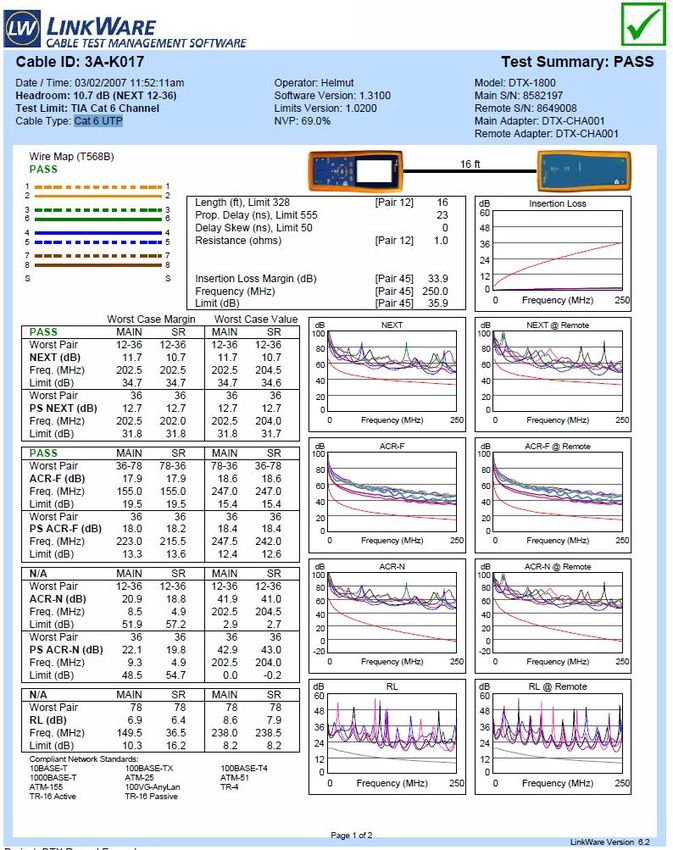
Table of Contents

Preface                                     3
Installer Credentials                       3
Means & Methods                             3
Deliverables                                3
Warranty                                    4
Definitions                                 4
Cable Type                                  5
Flush Mounting                              5
Surface Mounting                            6
Jacks/Faceplates/Raceway                    6
Drop Quantity                               6
        New Locations                       6
        Existing Locations                  7
Jack Labeling                               7
Data Center/Frame Room Configuration        8
MDF Configuration                           8
        Environmentals                      9
        Sizing                              9
IDF Configuration                           9
        Rack/Patch Panel Labels             10
        Environmentals                      10
        Sizing                              11
Special Considerations                      11
        Residence Halls                     11
        ePhones, CCTV & Sirens              11
        LCD Electronic Messaging            12
        Wireless Arrays                     13
Appendix A (Labeling)                       14
Appendix B (Fiber/LIU Labeling)             15
Appendix C (MDF/IDF Names)                  19
Appendix D (Sample Cut Sheet)               20
Appendix E (Communications Racks)           21
Appendix F (IDF/MDF Room Sizes,
        Rack Placement; Rack Usage Guide)   22
Appendix G (Means & Methods Boilerplate)    30
Appendix H (Reserved Cable & Icon Colors)   33
Appendix I (Sample Cable Test Report)       34
Appendix J (Design & Bid Doc Checklist)     39
12-month Document Change Log                40
Index                                       42

7/8/2021                             2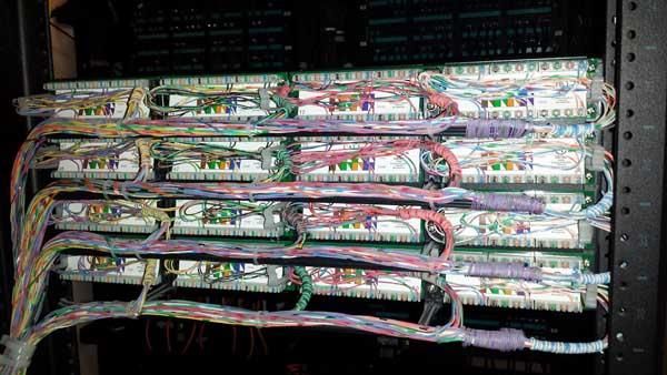
Preface:
Salem State University places a strong commitment to the communications infrastructure
that services the Administration, Faculty and Student body. As such, this infrastructure is
governed by a defined set of standards as presented in this document. This document is
more than a guide. The standards set forth in this document are to be adhered to
unless otherwise agreed upon, in writing, by the Director of ITS/Networking Services
or the CIO. With respect to Means & Methods, the Assistant VP, Campus Planning &
Facilities Management may also authorize exceptions. In the event of a conflict, the
specifications contained within the Salem State University Low-Voltage Wiring Standards
will take precedence. It is the responsibility of the Bidding Contractor to understand the
specifications and standards contained in this document and adhere to them. Bid
Specifications in conflict with this document may only take priority with written
approval by the Director of ITS/Networking Services or the CIO.

Version Control:
Every effort is made to distribute the most recent version of this document. While this
document has been carefully compiled and edited, occasionally clarifications and additions
are issued. The most recent version of this document is available
http://www.salemstate.edu/18860.php . Archival versions are available from Networking
Services upon request. The Standards document that is current at the time a contract is
signed will be the official Standards document for the life of that project, unless otherwise
agreed upon in writing. A 12-month Document Change Log is included at the end of this
document.

Installer Credentials:
Cabling contractors must be an approved vendor of the University, either by State ITT/ITC
contract, MHEC contract, University contract or competitive bid. All cabling products used
must meet IEEE specifications. Installation must follow BiCSi guidelines and adhere to
OSHA regulations. Installer must have a project manager who is BiCSi RCDD certified
overseeing any project greater than $5000. All cabling must be tested and a certification
report submitted to ITS/Networking Services. This testing may not take place without
proper termination of cabling in place. No project is considered completed until this
report has been presented and accepted. Minimum cable certification requirements and
sample reports are contained in Appendix H.

Means & Methods:
Installer will adhere to standards defined in the latest published edition of the BiCSi
Telecommunications Distribution Methods Manual for work environment, cable pulling –
including handling and securing, termination and testing. Appendix G contains a boilerplate
of procedures to be observed by the installer. A complete list must be obtained from the
Facilities Department at (978) 542-HELP.

Deliverables:
Upon completion of work, the installer will present a full certification report detailing that all
cabling falls within accepted industry standards. This report must be submitted in an
electronic format. The installer will also submit a jack cut sheet in the format specified in
Appendix C of this document. All station-lines run, whether coax or copper, must be
documented in the cut sheet. The cut sheets must also be submitted as an Excel
spreadsheet, in an .xls or .xlsx file. All deliverables are due 7 calendar days prior to
expected Certificate of Occupancy date.

    7/8/2021                                       3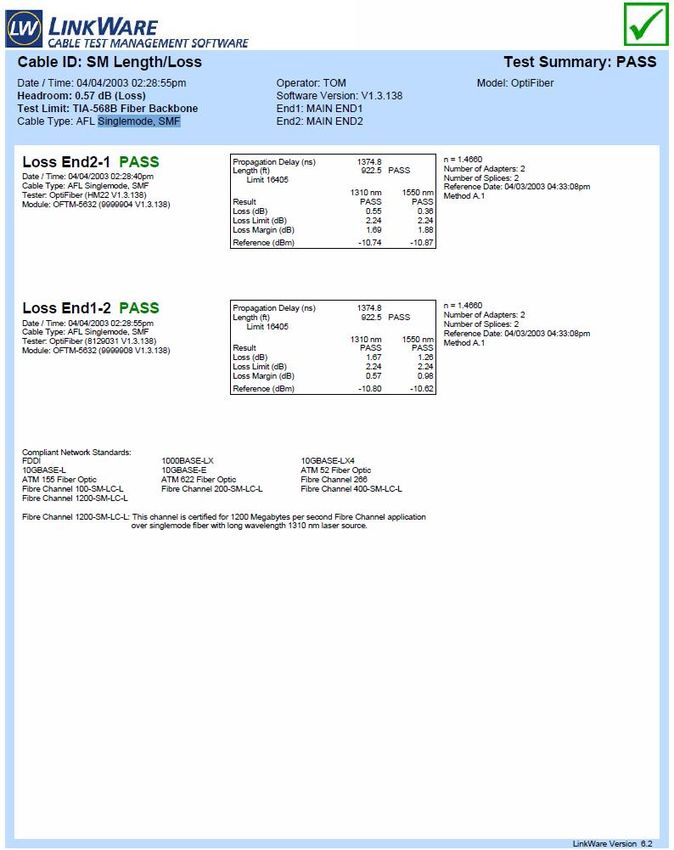
Warranty:
Warranties and guarantees will be provided at time of quote. No work performed will be guaranteed
for less than 5 years to be free of defect from installation error. Warranties will be in affect based
on manufacturer’s stated schedule.

Workmanship and quality:
Salem State University expects installations to be performed in a professional, clean and neat
manner. Wiring will be terminated per standards, but will also be dressed in, in a professional and
presentable fashion. All cable slack and service loops will be similarly dressed in and secured. It is
expected that all terminations will be completed to industry standards, regardless of a “Pass” in
testing. That is to say, Salem State will not accept minimal quality work. Samples of cable
terminations; dressing; fiber polishing are presented in Appendix G.

Definitions:
Station Wiring: All wiring installed between an IDF and a Location.

Location: A cluster of jacks containing any or all of the following low/no voltage wiring – Unshielded
Twisted Pair (UTP), Coax, Fiber and Audio Wire – for use in Data, Voice, Video and Audio
applications. “Location” is also referred to as “the Desktop.”

Drop: A single low/no voltage line within a Location.

Network port: A drop used for Network Access.
Voice port: A drop used for Voice Access.
Video port: A drop used for Video Access.

IDF: Intermediate Distribution Facility. The IDF is the central termination point for all station wiring.
It contains the network equipment necessary to provide connectivity between desktop computers
and the University Network. It may contain “hub” connectivity for Video. The IDF will contain “pass
thru” patch panels for Voice.

MDF: The Main Distribution Facility. MDF’s contain core or intermediate network equipment,
connectivity to the University Data, Telephone and Video “networks”, as well as Data, Telephone
and Video connectivity to the IDF’s. The MDF may also contain telephone equipment. An MDF
may also act as an IDF.

CDF: The Core Distribution Facility. CDF’s house the “collapse point” for infrastructure on each
campus. A CDF may also act as an MDF and IDF.

Rack Unit, “R.U.”, “U”: The standard measurement on a communications rack, amounting to 1 ¾”
(44.45mm). For the purposes of this document, “Rack Unit”, “R.U” and “U” are synonymous.

“Fiber can”, “can”, “Fiber enclosure”, “enclosure” and LIU are used interchangeably throughout this
document.

   7/8/2021                                       4
Cable Type:
The University does not designate station wiring as Voice or Data at the faceplate. This wiring
is ubiquitous to allow flexibility in usage. As such, all horizontal (station) cabling will EXCEED
Category 6 Standards (Category “6+”) or better unless otherwise specified, in writing. For
acceptable cable colors, please refer to Appendix H.

Fiber Optic Cable is used for connectivity between MDF’s as well as MDF to IDF (data only). In
the event that an IDF is within 90 Meters from its MDF, some UTP may, as defined by Project,
be run between these facilities. Both multimode and singlemode fiber is used from MDF to IDF
and MDF to MDF. Existing multimode fiber between MDF/IDF and MDF/MDF has been 62.5µ.
However, at this time, the University is in a period of transition with respect to its fiber
infrastructure. This transition necessitates the installation of both 62.5µ and 50µ multimode
fiber between MDF/IDF. MDF/MDF will remain 62.5µ. Factory-terminated LC pigtails with fusion
splices are to be used for all new fiber installations, whether single or multimode. Quantities are
defined by Networking Services, based on need. Fiber adapters in LIUs will be limited to 12
strands (6 pairs) per adapter. If a new LIU enclosure is required, it will be sized to
accommodate a minimum 50% growth. Because of their difficulty to work with, 1U LIU’s are to
be avoided.

Voice-Grade Copper is run between MDF and IDF’s to service voice needs on the riser. Either
Voice-Grade Copper or Fiber is used between MDF’s for voice, depending on the need and
density of telephones serviced by the facilities.

For video, unless otherwise specified, standard RG-6 (less than 150’) or RG-11 (greater than
150’) terminated with F-connections are to be used. MDF to IDF coax is standard ½” coax.
Two ½” cables are run between the MDF each IDF as well as between MDF’s (intra-campus
only). Standard termination applies. Terminations MUST be secure and not easily removed by
pulling.

Audio Cabling will be specified based on specific application.
For station-wiring, all wiring (data/voice/video, copper/fiber/coax) will be “home runs” from the
IDF to the wall plate. Use of mechanical connectors (e.g “barrel connectors”) is not permitted
nor are splice-points. This also applies to vertical risers from MDF to IDF with the exception of
riser voice trunks, where splice-points are acceptable. For external wiring, mechanical/fusion
splices may be used SPARINGLY as necessary or where required by code (indoor/outdoor
transition, lightning projection, etc).

All cables must be tested and certification reports submitted. Refer to Appendix I for
requirements and sample reports.

ALL WIRING MUST MEET IEEE SPECIFICATIONS AND BUILDING CODES FOR
INTENDED USE AND INSTALLATION CONDITIONS.

ALL CABLING INSTALLATIONS WILL PROVIDE A MINIMUM 1.5 METER DIAMETER
(APPROXIMATELY 16 LINEAR FEET) SERVICE LOOP AT THE IDF/MDF. THIS CABLING
WILL BE NEATLY COILED ON A WALL FIELD OR CABLE TRAY.

Flush Mounting:
Flush Mounting is the preferred method of mounting jacks at any given location.

7/8/2021                                     5
Surface Mounting:
Surface Mounting is only acceptable under two conditions – Flush mounting is not
possible due to construction of the wall or flush mounting is not practical because of the
application. An example of the former is cinderblock or poured-concrete construction.
For the latter, high-density areas such as computer labs.

Jacks/faceplates/raceway:
Residence Halls – Wherever possible recessed faceplates from Semtron with Ortronics
TracJack Clarity jacks are to be used. This applies to both new installations and
repair/replacement. Because of the unique installation requirements for the Semtron
faceplates, wherever its usage is not practical, the Ortronics Series II System is to be
used.

Other University Spaces – The University standard for Jacks and Faceplates is the
Ortronics TracJack System. New installations will use Ortronic TracJack. Where repairs
to legacy faceplates/jacks are required, these legacy systems are to be replaced by the
TracJack system. If an environment requires the use of more durable systems, the
Semtron should be used. When providing jacks to modular furniture, it is preferred that
the jacks be placed above desktop height whenever practical and allowed. If it is
necessary to install jacks under the work-surface, on the kick plate of modular furniture,
it is preferred that the faceplates be flush-mounted. In this instance, it may be necessary
to use Leviton 49910-Sx2 faceplates (for Steelcase furniture).

All cabling will be terminated under IEEE and BiCSi guidelines.

Under no circumstances will single-track raceway be used. The University has
standardized on Panduit multi-track raceway. All raceway will be mechanically secured
to the walls. Gluing is not acceptable.

Drop quantity:
New locations: The number of drops at a location is defined by a complicated set of rules
and needs. Exact numbers will be obtained through a location-specific identification.

The following can be used as general guidelines:
   • Common Areas: 2 – 4 UTP lines per location
   • Single Person Offices: 3 – 4 UTP lines + 1 coax (usually only 1 location)
   • Office Cubicles: 3 – 4 UTP lines per location
   • Multi-Person Offices: 3 – 4 UTP lines per location; Add 1 coax to 1 location only
   • Classrooms: 2-3 UTP in ceiling for wireless arrays; 3 UTP + 1 coax in front and
        back
   • Meeting Rooms: 2-3 UTP in ceiling for wireless; 3 UTP each location; 1 coax in
        front
   • Labs: 2-3 UTP in ceiling for wireless; sufficient wiring at each desk/table for
        computers; 3 UTP + 1 coax in front of room
   • Clerical Spaces (Copy/Storage Rooms): 4 UTP (usually 1 location)
   • Wall Phones/Emergency Phones: 1 UTP
   • Smart Classrooms: Wired as regular classrooms + 4 UTP/1 Coax in podium

NOTE: locations should only exist within a reasonable proximity to electric outlets. Also,
“Power Users” should have 1 or 2 extra UTP lines run to their work areas.

7/8/2021                                     6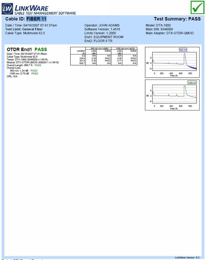
Existing Locations: –No area should be wired for exactly what is needed in order to
accommodate future growth. E.g. if 1 drop is needed, 2 or 3 should be run.
Wireless Arrays: -- The current wireless technology for the University is Aruba wireless
Access Points. Depending on the model required, these arrays require 1-3 data
connections. Exact drop quantity should be obtained by Networking Services.
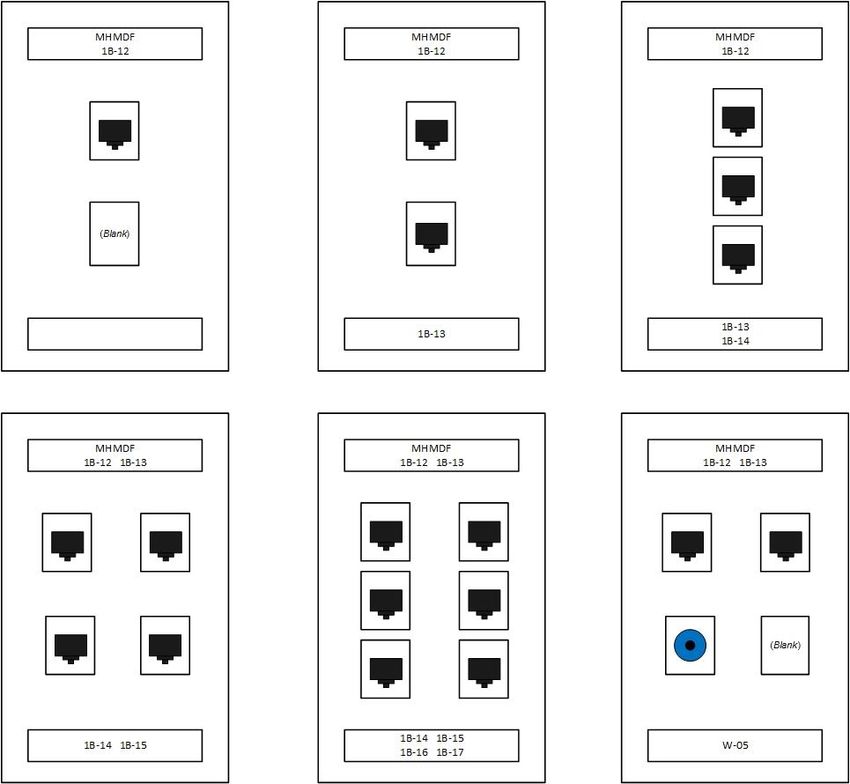
Jack Labeling:
All Jack labels will be placed under clear plastic inserts. Labels are not to be placed on
the surface of the faceplate unless an insert does not exist. In this instance, a single
layer of clear tape is to be placed over the label. Further, a label is to be placed on the
inside of the faceplate, also with a layer of clear tape over it.
Jacks are labeled using the following format:
-
E.g. If the faceplate contains jacks connected to ports 35 and 36 on Panel C (Rack
2) in the Library Level 0 IDF (ID0) the label would be (single or dual jack)
LIBID0
2C-35
[jacks]
2C-36
Faceplates with 3 or 4 jacks:
LIBID0
2C-35 2C-36
[jacks]
2C-37 2C-38
Faceplates with 5 or 6 jacks:
LIBID0
2C-35 2C-36
[jacks]
2C-37 2C-38
2C-39 2C-40
A chart listing “” names can be found in Appendix C. When adding
jacks to existing areas where labels follow an older standard, this new standard is to be
used on the new installations. Do not follow the older labeling scheme that may already
be present in that area. The racks, panels and ports remain consistent (see IDF
Configuration section).
More information on labeling of faceplates is available in Appendix A.
7/8/2021 7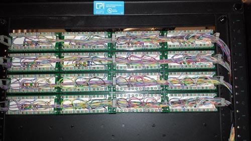
Data Center/Frame Room Configurations:
Fiber terminations: Both Multimode and Single mode fiber will be run between Data
Center/Frame Rooms and internal MDF/IDF’s. With respect to Multimode, both 50µ and
62.5µ will be run. Inter-building Multimode fiber will be 62.5µ. Both diameters of
Multimode fiber may be terminated in the same fiber can, provided they are separate
within the can (62.5µ on the far left; 50µ on the far right of the LIU) and clearly labeled
with the location name of the other end of the fiber, per Appendix C. Multi and single-
mode fiber are to be terminated in separate cans. Factory-terminated LC pigtails with
fusion splices are to be used for all new fiber installations. Fiber adapters in LIUs will be
limited to 12 strands (6 pairs) per adapter. If a new LIU enclosure is required, it will be
sized to accommodate a minimum 50% growth. 1U LIU’s are to be avoided.

Coax: If coax trunk lines are being fed in to the Data Center, they will be terminated
using the proper tap for the cable size per the Cable Company’s current standards. This
should be verified at time of installation. The placement within the Data Center is not
specifically defined, but there is an area set aside for coax.

Voice Copper: Where practical, voice applications outside of the Data Center ride over
fiber. However, instances arise where copper connections will be home-run from the
remote building to the Data Center. In these instances, the copper will be terminated on
Green Hamaco 66-block wall boards in the Data Center and 110/RJ-45 panels in the
remote Building MDF. If the telcom switch needs to be expanded, Purple Hamaco 66-
block wall boards will be installed with telco cables run between board and Telephone
Switch.

ALL CABLE TYPES WILL BE TRANSITIONED FROM OUTSIDE TO INSIDE cable
within the appropriate distances (in most cases 50’) of where they become accessible.
All copper will be transitioned to lightning protection ON BOTH SIDES of any run that
leaves a building, whether that run is exposed outside of the Data Center/Frame Room,
in any manner, or not.

See Appendix E – Racks and Cable Trays, for more information.

MDF Configuration:
An MDF will contain at least one (1) 19” Communication’s rack. Depending on the type
of equipment being placed in the MDF, this rack may be either an open box rack or a
standard relay rack (see Appendix E for rack descriptions). In general, one (1)
communications rack is sufficient for an MDF. If the MDF also acts as an IDF, additional
racks will be required as defined by “IDF Configuration” below.

UPS’s will need to be sized based on initial load and projected growth. However, in
general 2KVA of backup power is required for every 300 watts of load. If the room is on
a generator, this sizing can be halved. All UPS’s require a Network Management Card.
The UPS will back a standard 125v NEMA 5-20R 20A duplex or NEMA L5-20R twistloc
outlet to every communications rack in the room. Rack-mounted UPS’s will require an
open-box communications rack. The preferred standard for UPS’s is a single, larger
UPS supporting multiple closets. If this is not attainable, fewer/larger UPS’s supporting
multiple closets is preferred.

Both Multimode and Singlemode fiber will be run between MDF and IDF’s. With respect
to Multimode, both 50µ and 62.5µ will be run. Inter-building Multimode fiber will be

7/8/2021                                      8
62.5µ. Both diameters of Multimode fiber may be terminated in the same fiber can,
provided they are separate within the can (62. 5µ on the far left; 50µ on the far right of
the LIU) and clearly labeled with the location name of the other end of the fiber, per
Appendix C. Multi and single-mode fiber are to be terminated in separate cans.
Factory-terminated LC pigtails with fusion splices are to be used for all new fiber
installations. Fiber adapters in LIUs will be limited to 12 strands (6 pairs) per adapter. If
a new LIU enclosure is required, it will be sized to accommodate a minimum 50%
growth. All fiber terminations (CDF to CDF, CDF to MDF, MDF to MDF and MDF to IDF)
will use Ultra Physical Contact (UPC) connectors. However between CDF/CDF,
CDF/MDF and MDF/MDF, one (1) fiber pair of singlemode fiber will be terminated using
Angled Physical Contact (APC) connectors. The separation between UPC and APC
strands will be defined per Project and specified by Salem State Networking Services.

Voice trunks (copper) will be terminated on communications racks using 110/RJ-45
panels, unless otherwise specified by Telecommunications or Networking Services.
Blocks coming from the Telecom Switch Room will be Green. Blocks going to the IDF
will be Blue. If color panels are not available, icons are acceptable. Whether initially
using them or not, all panels must support snap-on icons. Standard bundled voice-
grade copper will be used for these trunks. Voice riser-trunk panels will be installed
below Outside Plant Copper Trunk panels. Panels should be distributed across racks in
a balanced fashion.

Specific lighting need not be specified beyond whatever is suitable for the room size.
However, the lighting should produce a minimal amount of heat. It is also highly
desirable that lights be placed both in front and behind communications racks rather
than directly above.

Cable management in an MDF will follow the same specifications/requirements as IDFs.

Environmentals: The MDF must be a secure room and humidity levels must remain
above 40% and non-condensing. At a minimum, active venting is required for all MDF’s.
If temperatures remain between 55-78 degrees Fahrenheit, no cooling is necessary. If a
room cannot maintain a temperature above 55 degrees Fahrenheit, heating and
humidification may be required.

Room Size: Appendix F contains drawings showing preferred layouts, room dimensions
and spacing for MDF and/or IDF’s. It also lists room requirements.

See Appendix F – Racks and Cable Trays, for more information

IDF Configuration:
In an IDF, one (1) communications rack will be required for every 14 cumulative “u’s” of
patch panels (combination of Data, Trunk/Riser Voice and/or Video) and fiber cans. For
each fiber can and each voice-trunk panel installed, a 2 u cable manager will be
installed. For every 24-ports of data network equipment, a 1 u cable manager will be
used. In addition, 6” wide x 13” deep vertical cable management will be installed at the
ends/between all racks. If space does not permit the use of 6” wide cable management,
3.75” may be used on the ends only.

The Standard horizontal cable manager is TrippLite SRCABLEDUCT2UHD . The
standard vertical cable manager is the Ortronics OR-DVMS706 (6”) or OR-DVMS704
(3.75”).

7/8/2021                                     9
Refer to Appendix F for minimum room dimensions, rack placement and clearances.

All station wiring is to be terminated in a patch panel (See Cable Type for requirements).
Voice trunk and riser panels may be Category 3. All new patch panels are to be
Ortronics. Under no circumstances are 110/66 wall-blocks to be used in IDF’s for voice.
A patch panel will be placed at the top of each communications rack, or if a fiber can is
also housed in the rack, under it for Voice Trunk ports only. If the IDF contains more
than one (1) rack, the quantity of Voice Trunk ports will be divided equally to each rack.
The Voice Trunk panels will be color Blue to differentiate them from the station wiring
panels. Station wiring panels will be black. Alternatively, blue or black “icons” may be
used on the patch panels to differentiate between Trunk and Station ports. All panels,
whether Category 3 or 6, must support the use of icons. As with MDF’s, multimode and
single mode fiber will be terminated in separate cans. 50µ and 62.5µ fiber may be
terminated in the same can, provided they are separated and clearly labeled. 62.5µ fiber
will be terminated on the far left of the LIU, 50µ on the far right. If space does not permit
this, cabler is not to make assumptions on placement; placement must be clarified with
Salem State.

All Video cabling (RG-6 for distances less than 150’, RG-11 for distances greater than
150’) will be terminated at a wall field, where University Cable TV distribution is located.
One pair of RG-11 cables will be run between an MDF and any IDF serviced by it.

Rack/Patch Panel Labels:
Starting at the top of rack 1 (defined in next paragraph) and moving down the rack each
panel will be labeled sequentially starting with “A” (ie Rack 1 Panel A). Moving down
Rack 1, the next panel will be “B”, and so-forth. Moving to the rack to the right, the patch
panel at the top of the second rack is Rack 2 Panel A and so forth. A label may be
placed at the top of each rack designating the Rack number and a separate label placed
on each patch panel designating the panel letter. Only copper panels (voice trunk
and station cabling) are to be labeled with letters. LIU’s will be labeled to identify
location of far end of fiber.

Rack 1 is the “left-most” rack. Using the common left-to-right Western reading format,
the “left-most” rack is the rack that is logically the starting point within the room. More
information is available in Appendix A.

If the patch panel comes with factory numbering, it will not be altered/overlaid. If the
patch panel does not come factory numbered, each patch panel will be numbered
independent of others (ie the first port on each panel will start at “1”).

Environmentals: The IDF must be a secure room and humidity levels must remain above
40% and non-condensing. At a minimum, active venting is required for all IDF’s. If
temperatures remain between 55-78 degrees Fahrenheit, no cooling is necessary. If a
room cannot maintain a temperature above 55 degrees Fahrenheit, heating and
humidification may be required.

One duplex 20A 110 outlet per communications rack is required. A minimum of a
1.5KVA SNMP-Manageable UPS will be placed in each IDF. UPS’s will need to be
sized, but in general 1.5KVA of battery backup is needed for every 300 watts of power
consumption. All UPS’s require a Network Management Card. Rack-mounted UPS’s will
require an open-box communications rack. The preferred standard for UPS’s is a single,

7/8/2021                                     10
larger UPS, placed in the MDF, supporting multiple closets. If this is not attainable,
fewer/larger UPS’s supporting multiple closets is preferred.

Room Size: Appendix F contains drawings showing preferred layouts, room dimensions
and spacing for MDF and/or IDF’s. It also lists room requirements.

See Appendix F – Racks and Cable Trays, for more information

Special Considerations
Residence Halls:
It has been our experience that the data jacks used in the offices, classrooms, labs and
common areas throughout the University are not suited to the energetic behavior of
resident students in their rooms. After extensive research, we found the Semtron
recessed faceplates and Ortronics TracJack Clarity jacks to be the most durable.
Wherever possible, the Semtron plates are to be used. When an existing faceplate
needs to be replaced, a Semtron should be used, if possible. When it is impractical to
use the Semtron faceplate, Ortronics TracJack faceplates and jacks are to be used. To
be consistent, Semtron faceplates (with TracJack Clarity jacks) should be used
throughout residence halls, not just in living spaces. Networking Services should be
consulted to verify the current product to be used for faceplates as more durable
products are continually being researched.

Wiring Quantities: 2 UTP (voice and data) “per pillow” + 1 coax per room. It has been
our experience that rooms get over booked. Rooms should have 1 location per
designed capacity + 1 extra location (e.g. a double room should have 3 locations).
Common Areas should have 3 UTP per location. At least one location per Common
Area will have 1 coax. When wiring for a flat-panel TV, the Semtron recessed
faceplates are preferred. Because of the torque that RG-11’s place on the back of
faceplates, a short “pigtail” transition from RG-11 to RG-6 OR a 45° connector on the
RG-11 should be used.

Semtron part numbers (for use with Ortronics TracJack Clarity jacks):
  • Single port: 1-0RE-TJ
  • Dual port:    1-0RE-2TJ
  • 3-port:       1-000RE-TJ
  • 4-port:       1-0000RE-TJ

ePhones & CCTV:
At present, there is no standard in place defining what the cable bundle to an ePhone
should be. At a minimum, an ePhone requires a standard telephone line. If a
strobe/emergency light will be installed, power will need to be supplied. Similarly,
wherever a CCTV camera will be present, coax, power and pan/tilt/zoom (PTZ) control
lines (UTP) will be needed.

Minimum ePhone & CCTV Cable specifications:
ePhone
       Category 3 or better UTP or STP
       Light Red icon on patch panel (if legacy patch panels are in place that do not
       support icons a pink patch cable or other pink identifier may be used)

7/8/2021                                    11
CCTV Camera
2 Strands Multimode (62.5µ) fiber (less than 2000 meters) or
Singlemode fiber (more than 2000 meters)
Siren
2 Strands Multimode (62.5µ) fiber (less than 2000 meters) or Singlemode
fiber (more than 2000 meters). If a CCTV Camera is present, the siren
may use the same fiber installed for that application. In this instance, a CM2
copper/fiber transceiver at the camera location will be used to manage both
requirements.
Power for CCTV and/or Strobe/Marker Light
18/2 UTP (less than 100’)
16/2 UTP (less than 150’)
*
When using coax, 100% copper center conductor and a copper braid coverage of 96%
or better.
LCD Electronic Messaging System (Digital Signage)
In 2006 the University designed and implemented an Electronic Messaging System
utilizing existing plasma TV’s, later expanding to LCD and now LED units. For the
purposes of this document, the following components/cabling standards/installation
requirements apply:
It is beyond the scope of this document to specify the Screen hardware, however
Networking Services should be consulted before any unit is purchased to ensure its
compatibility and suitability. In general, the following specifications should be met:
• Standard Mounting Pattern
• HDMI Interface, with video support for 1280x768
• Serial Control Port
The mounting of the LED will, in most cases, be performed by the cable-installer. It is
expected that the mount will be properly secured per the weight-based guidelines of the
manufacturer using appropriate fasteners and adhering to the policies of the University’s
Facilities department.
Once a location has been identified for the location of the LED, a suitable mount will
need to be selected. It is preferred that the mount be installed prior to running any
cabling. This may not be consistently practical, but the goal is to place the data jack
behind the LED such that it is minimally/not noticeable. If the wiring location is placed
prior to installation of mount, the mount should take aesthetics (hiding the cables) into
consideration.
For each LED, the data-run will consist of three (3) Category 6* cables and one (1) low-
skew cable. The low-skew cable will be terminated in the lower-right position on the
faceplate onto a green jack. The remaining 3 cables may use any other appropriately-
colored jack that matches the faceplate, but all 3 will be the same color. In the event
that a green jack is not available, a green icon is acceptable. Wherever possible, the
Semtron recessed faceplate should be used in the installation of wall-mounted screens.
*Specific manufactured cables must EXCEED Category 6 specifications (e.g Cat “6+”).
See Cable Types for more information.
7/8/2021 12Wireless Arrays The University has standardized on Aruba wireless Access Points for wireless networking connectivity. For best coverage, these units need to be mounted parallel to the floor/ceiling. Wall mounting will require L-brackets. All deviations from this must be approved through Networking Services. Networking Services will provide locations for all wireless array installations or relocations When mounting a wireless array to an acoustical ceiling tile (ACT), the mounting bracket is to be centered on the tile and not attached to the ceiling grid. To add support to the tile, a 24” length of metal stud is to be placed above the tile such that it sits in the ceiling grid. The stud segment will have a hole punched in it to allow the necessary cabling to pass through. Cut ends of the stud will be covered with tape to eliminate sharp edges. The stud will also be chained in the same fashion that a light fixture would be secured in a suspended ceiling. The responsibility of the low-voltage contractor with regard to hanging the actual electronics (provided by the University) will be project-dependent. In some cases, the contractor will only install the mount and SSU personnel will install the actual arrays. 7/8/2021 13
Appendix A

                                  Jack Labels

NOTE: When installing a coax port on a recessed (Semtron) faceplate with 3
jacks, use a 4-position plate with a blank. Do NOT install coax on the bottom of a
3-position recessed plate.

                           Rack/Patch Panel Labels

7/8/2021                               14
Appendix B
Fiber LIU Labeling
Salem State currently utilizes multimode (62.5µ and 50µ) and singlemode fiber
with either ST or LC connectors. The labeling standards documented below are
independent of the fiber type (single or multimode). ST connectors are being
phased out. When re-terminating, unless otherwise specified LC
connectors/packs should be used. All new installations will use LC connectors.
NOTE: ST and LC packs may be mixed in the same LIU. While exceptions are
made based on requirements and space, fiber modes should not be mixed in the
same LIU. At no time shall they be mixed on the same pack. 62.5µ and 50µ
multimode may be mixed in the same LIU, but never in the same pack.
ST LIU/Pack labeling
Factory labeling of slots in LIU’s take many forms:
1) 4u vertical pack LIU with 62.5µ (A-G) & 50µ (K-M) multimode, LC
terminations
A B C D E F G H I J K L M
1 1 1 1 1 1 1
H I 1 1 1
2 2 2 2 2 2 2 2 2 2
3 3 3 3 3 3 3 3 3 3
4 4 4 4 4 4 4 4 4 4
5 5 5 5 5 5 5 5 5 5
6 6 6 6 6 6 6 6 6 6
2) 4u vertical pack LIU with 62.5µ (A-G) multimode, ST terminations
A B C D E F G H I J K L M
1 1 1 1 1 1 1
2 2 2 2 2 2 2
3 3 3 3 3 3 3
4 4 4 4 4 4 4
5 5 5 5 5 5 5
6 6 6 6 6 6 6
7/8/2021 153) 2u horizontal pack LIU with 62.5µ multimode, ST terminations
A C
1
1
2
5
3
5
3
6
2
6
4
4
B D
1
1
2
6
3
5
3
5
2
6
4
4
4) 2u horizontal pack LIU with singlemode, LC terminations
A C
3
5
1
2
6
4
3
5
1
2
6
4
B D
3
5
1
2
6
4
3
5
1
2
6
4
5) 2u horizontal pack LIU with singlemode, LC terminations (A-C)
A B
3
5
1
2
6
4
3
5
1
2
6
4
C D
3
5
1
2
6
4
NOTE the positions of packs B and C in this LIU compared to units #3 and
#4
Pack orientation
LC Connectors
1
2
7/8/2021 16For vertical pack, fiber strand 1 is in the upper left. For horizontal pack, fiber
strand 1 is in the lower.
ST Connectors
1
2
1
2
For vertical pack, fiber strand 1 is on top. For horizontal pack, fiber strand 1 is on
the left.
For all pack types, only factory labeling is used on packs. However, for internal
use, ST strands are labeled as 1, 2, 3 etc, but LC strands are labeled as 1a, 1b,
2a, 2b … That is to say, since LC fiber is terminated in pairs, PAIR 1 is
considered 1a, 1b; PAIR 2 is considered 2a, 2b; etc.
More information on terminating and polishing fiber connectors is available in
Appendix G.
7/8/2021 17Appendix C
MDF/IDF Names
Old Label Old Description New Label New Description
acbmdf Academic Building MDF ACBMDF Academic Building MDF
adnxmdf Admin Annex MDF ADNXMDF Admin Annex MDF (HR Trailer)
adbmdf Administration Buildng MDF ADBMDF Administration Buildng MDF
adbidf Administration Building IDF ADBIDF Administration Building IDF
adhmdf Admissions House MDF LORING35MDF 35 Loring Ave MDF
ah108a Alumni House MDF 108a AHMDF Alumni House MDF 108a
ahidf Alumni House IDF AHIDF Alumni House IDF
audframeroom Auditorium Frame Room AUDMDF Auditorium Frame Room
batesa Bates A BATESA Bates A
batesb Bates B BATESB Bates B
batesc Bates C BATESC Bates C
batesd Bates D BATESD Bates D
batese Bates E BATESE Bates E
batesf Bates F BATESF Bates F
batescommons Bates Commons BATESCOMMONS Bates Commons
bhmdf Bowditch Hall MDF BHMDF Bowditch Hall MDF
bhid3 Bowditch Hall 3rd Floor IDF BHID3 Bowditch Hall 3rd Floor IDF
bhid6 Bowditch Hall 6th Floor IDF BHID6 Bowditch Hall 6th Floor IDF
b1mdf Building 1 MDF (Data Center) B1MDF Building 1 MDF (Old Data Center)
b1126 Building 1 126 B1ID1A Building 1 126
b1170 Building 1 170 B1ID1B Building 1 170
b1256 Building 1 256 B1ID2 Building 1 256
b1lib Building 1 Library B1LIB Building 1 Library
baseball Baseball Field BASEBALLMDF Baseball Field
catcove Cat Cove CATCOVEMDF Cat Cove
ccrh117b CCRH MDF 117b ATLANTICMDF Atlantic MDF 117b
ccrh225a CCRH 225a ATLANTICID2A Atlantic 225a
ccrh234a CCRH 234a ATLANTICID2B Atlantic 234a
ccrh317 CCRH 317 ATLANTICID3 Atlantic 317
ccrh407b CCRH 407b ATLANTIC4A Atlantic 407b
ccrh414 CCRH 414 ATLANTIC4B Atlantic 414
ciemdf CIE MDF CIEMDF CIE MDF
dcidf Dining Commons IDF DCMDF Dining Commons IDF
dove Dove – 57 Loring Ave LORING57MDF 57 Loring Ave
ecmdf Ellison Campus Center MDF ECCMDF Ellison Campus Center MDF
ecentermdf Enterprise Center MDF ENTMDF Enterprise Center MDF
ecenteridf Enterprise Center IDF ENTIDF Enterprise Center IDF
hbmdf Harrington Building MDF HBMDF Harrington Building MDF
hbidf Harrington Building IDF HBIDF Harrington Building IDF
7/8/2021 18hmmdf Horace Mann MDF HMMDF Horace Mann MDF
NA NA LAMDF Lafayette Annex (287 Lafayette)
NA NA LA331MDF 331 Lafayette MDF
libid0 Library Level 0 IDF LIBID0 Library Level 0 IDF
libmdf Library Level 1 MDF LIBMDF Library Level 1 MDF
libid3 Library Level 3 IDF LIBID3 Library Level 3 IDF
marsh105 Marsh105 MARSHMDF Marsh 105
marsh168 Marsh168 MARSHID1 Marsh 168
marsh230 Marsh230 MARSHID2A Marsh 230
marsh268 Marsh268 MARSHID2B Marsh 268
marsh326 Marsh326 MARSHID3A Marsh 326
marsh368 Marsh368 MARSHID3B Marsh 368
marsh426 Marsh426 MARSHID4A Marsh 426
marsh468 Marsh468 MARSHID4B Marsh 468
marsh526 Marsh526 MARSHID5A Marsh 526
marsh568 Marsh568 MARSHID5B Marsh 568
mh209 Meier Hall MDF 209 MHMDF Meier Hall MDF 213
mh215 Meier Hall 215 MHID2 Meier Hall 216
mhfanroom Meier Hall Fan Room MHID1 Meier Hall Fan Room
mh326 Meier Hall 326 MHID3 Meier Hall 326
okcmdf Okeefe Center MDF OKCMDF Okeefe Center MDF
okcidf Okeefe Center IDF OKCID3 Okeefe Center IDF 3rd floor
NA NA OKCID1 Okeefe Center IDF Fitness Center
okcfield Okeefe Center Field OCKFIELD Okeefe Center Field
phmdf Peabody Hall MDF PHMDF Peabody Hall MDF
phid3 Peabody Hall 3rd Floor IDF PHID3 Peabody Hall 3rd Floor IDF
phid6 Peabody Hall 6th Floor IDF PHID6 Peabody Hall 6th Floor IDF
publicsafety Public Safety POLICEMDF Public Safety MDF
NA NA POLICEIDF Public Safety IDF
stanleymdf Stanley Building MDF STANLEYMDF Stanley Building MDF
NA NA STANLEYDC Stanley Building Data Center
sbmdf Sullivan Building MDF SBMDF Sullivan Building MDF
sbidf Sullivan Building IDF Attic SBIDF Sullivan Building IDF Attic
tennis Tennis Court TENNISMDF Tennis Court
NA NA VHMDF Viking Hall MDF (West bar)
NA NA VHID2W Viking Hall West bar 2nd Floor IDF
NA NA VHID3W Viking Hall West bar 3rd Floor IDF
NA NA VHID4W Viking Hall West bar 4th Floor IDF
NA NA VHID1E Viking Hall East bar 1st Floor IDF
NA NA VHID2E Viking Hall East bar 2nd Floor IDF
NA NA VHID3E Viking Hall East bar 3rd Floor IDF
NA NA VHID4E Viking Hall East bar 4th Floor IDF
7/8/2021 19Appendix D
Sample Cut Sheet:
Wiring JACK Room
RACK PANEL PORT
Closet Number
MHMDF 1 B 1 112
MHMDF 1 B 2 112
MHMDF 2 B 3 151
MHMDF 2 C 1 151
MHMDF 3 B 1 151
MHMDF 3 C 1 152
MHID3 1 B 1 200
MHID3 1 B 2 200
MHID3 1 B 3 203
MHID3 2 B 1 204
MHID3 2 C 1 204
MHID3 2 C 2 206
7/8/2021 20Appendix E
Racks & Cable Trays
Standard Single Relay Rack:
Single Relay Racks are the standard “flat” racks used for patch panels and equipment
that requires only a two-point mount. The University no longer standardizes on a
specific manufacturer, however the following criteria must be met:
• 19”
• 84”/45-Rack Units
• Threaded mounts (no clips)
• Minimum 700lbs capacity
• Rack Units must be stamped into finish of rack and visible
• Black finish
• When adding a rack to an existing IDF, the new rack must match existing racks
as closely as possible.
This rack type is used in both MDF’s and IDF’s. All racks in a closet must be the same
design. If adding a rack to an existing closet, new rack must match existing racks as
closely as possible.
Open Box Rack:
An Open Box Rack is similar to the traditional Rack Enclosure, used for equipment that
requires a four-point mount. However, the Open Box Rack does not have front, back,
side or top panels. It does, however, have power distribution. At this time, the standard
is not defined. However, 7’ x 36” racks are recommended.
This rack type is used in MDF’s only.
Rack Enclosure:
The traditional box enclosure with sides, top, door and back.
At this time, the standard is not defined. However, 7’ x 40” racks are recommended.
This rack type is used in MDF’s and where ever a lockable rack is needed.
Cable Trays
Cable trays will be installed above communication racks, parallel to the face of the racks.
Ceiling heights should accommodate trays for applicable usage and codes. Tray
installations will be designed based on local need, however generally speaking they will
be no less than 12” wide. Ladder tray is acceptable in most cases, however specific
applications may call for mesh-basket or solid/enclosed trays.
Trays will also be installed along the ingress/egress path inside an IDF/MDF/CDF to
support cables not wholly contained in that space. If necessary and agreed upon, D-
rings and/or J-Hooks may also be used.
7/8/2021 21Appendix F
MDF/IDF Room Size Requirements:
The following guidelines should be followed when configuring an MDF or IDF
• A margin of 6” must be maintained between the swing of the door and the front of
a communication rack
• A margin of 2” must be maintained between the swing of the door and the side of
a communication rack
• Ceiling heights are a minimum of 8’. Since fire codes usually require a minimum
distance of 18” from a sprinkler head and to accommodate cable trays, a 9 ½’ or
higher ceiling is preferred. A finished ceiling is not required in a wiring closet.
However, if the decking material is prone to flaking, a ceiling is preferred.
• Port counts are determined by the TOTAL number of Voice Trunk Ports (building
feeds and riser), Station Ports (Cat 6*), fiber ports and Video ports (Coax) in a
closet.
Specific cabling must exceed Category 6 specifications (e.g “Cat 6+”). See Cable
Types for more information.
The table below is an APPROXIMATION of space required for data closets. These
measurements are based on open, unobstructed floor space. Obstructions may
include support columns, floor-corings, security enclosures on walls, electrical
conduits, wall-mounted panels, electrical sub-panels non-standard racks, etc. If such
obstructions/additions are present, additional space will be needed. ONLY DEVICES
RELATED TO IT SERVICES ARE TO BE INSTALLED IN MDF/IDFs.
Total Ports Racks Needed Min Room Size2
Local UPS’s: If not on a central UPS, outlets are to be placed at standard (16”) height
at locations marked. At least two Duplex outlets (A and B) are required, and on separate
circuits. For closets with more than 2 racks, each rack will require a separate duplex
outlet. No more than 2 Duplex outlets are to be on the same circuit.
Unless otherwise specified, outlets are NEMA 5-20R. Power Distribution Units currently
in use require L5-20R receptacles. If local Uninterruptable Power Supplies (UPS) are to
be used to support more than 2 racks, 1 or more L5-30P receptacles may be needed.
Because of an increased dependence on the network for security devices new,
renovated and upgraded data closets should be placed on emergency generator power.
Room and Equipment Measurements
Rack-to-Front/Back Walls
Measurements based on standard 19” Relay Rack; Measurements taken from FRONT
of vertical support, where equipment would be screwed to rack.
• A MININUM of 43” is required from the FRONT of a rack to the FRONT wall (or
FRONT of opposite rack, if using two rows of racks).
• A MINIMUM of 38” is required from the FRONT of a rack to the BACK wall.
Rack-to-Side Wall
• If vertical cable management is installed A MINIMUM of 24” is required from the
end of the last communication rack in a row to the side wall;
• If vertical management is not yet installed, the MINIMUM distance from the end
of the last rack to the side wall is 30”.
1
- Central UPS outlets (standard NEMA 5-20R). If twistloc (e.g L5-20R) outlets are
required, there should be one (1) receptacle per rack, centered above rack.
2
A/B
- Local UPS outlets
Rack Measurements (looking down on rack)
1
Vertical cable managers (on sides of rack)
2
Top horizontal support of rack
3
Floor brackets
3
11/16"
13 ½”
3'-11/16"
1/8"
3'-615"
8 3"
1 2 1
3
4'-6"
20 ½”
61'-5"
¼”
7/8/2021 23Front
A/B
3'-7" 3'-2"
Sample
Network
Device
2'-6"
2'-0"
Front
A/B
3'-7" 3'-2"
Sample
Network
Device
2'-6"
Front
2'-0"
7/8/2021 24Front
B/C
A
3'-7" 3'-2"
Sample
Network
Device
2'-6"
Front
2'-0"
Front Front
A/B
A/C
3'-2" 3'-7" 3'-2"
Sample Sample
Network Network
Device Device
2'-6"
Front Front
2'-0"
7/8/2021 25Front Front
A/D
B/C
A
3'-2" 3'-7" 3'-2"
Sample
Network
Device
Front
Sample
Network
Device
2'-6"
Front
2'-0"
7/8/2021 26Front Front
D/E
B/C
A
A
3'-2" 3'-7" 3'-2"
Sample Sample
Network Network
Device Device
Front Front
2'-0"
7/8/2021 27Front Front
A/B
C/D
E/F
A
3'-2" 3'-7" 3'-2"
Sample
Network
Device
Front
Sample
Network
Device
Front
2'-0"
IDF/MDF/CDF Room Signage
For security purposes, Communications Closets (IDF/MDF/CDF) should not be labeled
as such. Only a room number should be placed at the door.
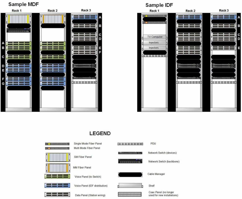
7/8/2021 28Sample equipment, panel, shelf, LIU placement guide (within racks)
This section is meant as a guide for the placement of equipment, shelves, low-voltage
wiring, etc within racks.
Data closets (IDF’s, MDF’s, Telecom Frame Rooms, etc) are secure facilities. They are
not to be used for storage of non-IT equipment. Services unrelated to security and IT
are not to be installed in data closets. Third party equipment relating to security is to be
coordinated with Networking Services BEFORE mounting/installing/configuring in a
data closet.
7/8/2021 29Appendix G
Means & Methods Boilerplate:
The following is a meant as a minimal set of guidelines for any installation/renovation of
data, video or voice cabling at Salem State University. As of 27 February 2004, these
were the most up to date specifications. A more complete and up to date guide may be
obtained through the Facilities Department by calling (978) 542-HELP.
• All wiring/cabling will be installed as per BiCSi specifications and will be properly
supported from the building’s structural elements, independent of any drop
ceilings or other suspended building systems.
• All ceiling tiles, removed or pushed away, will be properly reinserted by the close
of business each day. It is the responsibility of the contractor to provide all
ceiling tile replacements necessary. The contractor is also responsible for the
repair of any property damage that may occur by them, their vendors or their
subcontractors. ALL damage is to be reported as soon as possible to Facilities
to help facilitate timely repairs. Facilities can provide specifications for our
institutional standards as required.
• All trash generated by the contractor must be removed from the University by the
vendor at the close of each business day and the work area will be broom swept
before the contractor leaves each day. Construction materials are not to be
placed in University trash receptacles or dumpsters. Should a dumpster be
required by the contractor, the Office of Facilities Management will assist in
identifying a location.
• All exposed conduit/raceways will be installed in a neat and workmanlike
manner. All conduit/raceway will be mechanically fastened to the support
structure.
• All wall penetrations will be appropriately filled with material appropriate for the
purpose. All firewall penetrations are to be specifically noted and reported to the
Facilities Office for inspection. In the event that an existing penetration that was
not previously filled is reused, the contractor must seal that penetration.
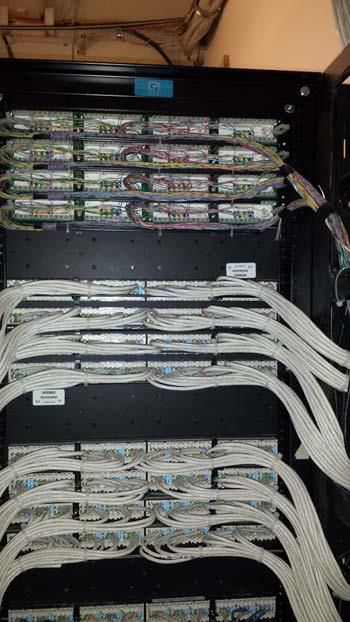
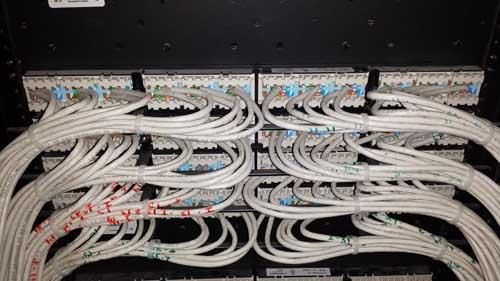
The following photos are meant as a guide to represent what is expected in the
quality of cable terminations and fiber polishing. Salem State expects the quality
of all work to meet or exceed these samples.
7/8/2021 30Note that strain-relief is to be used for all
copper cabling. Cables will be dressed in
to the strain-relief with either Velcro or zip
ties. Further, all cable bundles will be
dressed in at no greater than 36” segments
where visible and no more than 60”
segments where not in cable tray.
7/8/2021 31The following are examples of incomplete polishing of fiber connectors. These connectors will pass testing, but are not acceptable (magnification 200X using JDSU P5000i microscope): The following is a completely polished fiber connector: Networking Services requires that all fiber strands that are field-terminated use Apoxy/Polish terminations rather than Unicam. 7/8/2021 32
Appendix H

                                Reserved Cable and Icon Colors

Unless otherwise specified or agreed upon in writing, the following colors will be used for
copper wiring:

Station Wiring (in-wall):
Category 6 family:   Black2
Category 5e:         Blue2 or White2
Wireless:            Orange
Low-skew:            Grey, Maroon

Patch cables:
Category 6 family:           Black2
Category 5e:                 Blue2, White2
Wireless:                    Orange
Crossover:                   Red

Security devices (ePhones, CCTV, etc) do not require a different color cable (horizontal
wiring or patch). However, they are to be marked using light red icons at each Patch
Panel port.

RESERVED ICON COLORS
Light Blue (Ortronics OR-40326500) –                   Telephone (non-security)
Light Red (Ortronics OR-40322500) –                    Security (ephones, cameras, etc)
Light Orange (Ortronics OR-40323500) –                 Wireless Arrays
Purple (Ortronics OR-40327500) –                       A/V devices
Light Green (Ortronics-40325500) –                     Low Skew

RESERVED CABLE COLORS (in wall)
Black     Category 6 family horizontal wiring AND patch cables
White     Category 5e horizontal wiring AND patch cables
Blue      Category 5e horizontal wiring AND patch cables
Grey      Low-skew
Maroon    Low-skew
Orange    Wireless Access Point/Array
Purple    Facilities’ Functions/Building Controls
Red       Crossover patch cables

Color Consistency
Patch cables are to be a consistent color within a closet for a given application (ie
Category 5e cables may be Blue or White, but only one of those colors is to be used in
any single IDF). Similarly, horizontal station cabling for each wiring closet will be the
same color for each Category-grade of copper.

CONTRACTORS ARE RESPONSIBLE FOR PROVIDING ENOUGH ICONS OF
EACH COLOR BASED ON CABLE TYPES INSTALLED.

2
    Wireless feeds will be Orange, whether Cat 5e or Cat 6

7/8/2021                                              33
Appendix I
Cable Certification Requirements & Sample Cable Test Reports
The following are the minimum testing requirements to be submitted for Coax (video),
UTP (xBaseT/Data), Telco trunk and Fiber Optic (Single and Multimode). Note, a value
of “Pass/Fail” is only acceptable for non-quantifiable values (e.g presence of mechanical
connectors) and for an overall rating of the cable. Actual values are otherwise expected.
Coax (75Ω)
Length
Continuity
Short identification
Splitter/mechanical connector identification
Overall Pass/Fail
UTP (Category 5e @ 100MHz, Category 6 family @ 250MHz)
Length
Crossed-wire identification
Crossed pair identification
Continuity/Split-wire identification
Insertion loss fault
Bandwidth fault
Delay skew
dB loss
Mechanical connector/splice identification
Overall Pass/Fail
Telco trunk
Open-loop conductor identification
Low-loop current
High-loop current
Short identification
Crossed-pair identification
dB loss
split connections
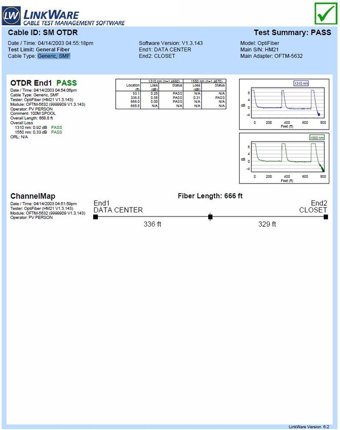
Fiber Optic cable (Multimode @ 850/1300nm, Singlemode @ 1310/1550nm)
OTDR trace, identifying:
Wavelengths
Cable length
Power loss (dB)
Faults (breaks, splits, cracks, faulty connectors)
Presence of mechanical/fusion splices
Overall Pass/Fail
7/8/2021 34The following are sample Certification Reports. Not all cable types are represented in these samples. The samples are meant as a guideline. Graphs are required for all fiber documentation. They are preferred, but not required, for Category 6 family of cabling. Graphs are not necessary for copper cables of quality less than Category 5e. While the samples below come from Fluke, Salem State University does not endorse or require the use of any particular cable reporting tool. 7/8/2021 35
7/8/2021 36
7/8/2021 37
7/8/2021 38
Appendix J

                     Design & Bid Document Inclusion Checklist

The following items should be included in Bid Specifications for Construction and Renovation
Projects. All items below are relevant to new construction. With respect to renovated spaces,
ITS/Networking should be consulted prior to issuing bid documents to verify applicable items.

This appendix is meant as a template to remind those creating bid documents of the items that
should be included in those documents. By including those items, it is implied that those items
will comply with the standards defined in this document with respect to material, quality, quantity
and installation.

MDF/IDF
  □ Racks
  □ Rack placement
  □ Pathways in to MDF/IDF, Cable Tray, Capacity
  □ Room Size
  □ Cable Management – vertical and horizontal
  □ Electric – PDU’s, UPS’s (local or central), outlets (quantity, location, type), Room Lighting
  □ HVAC – Cooling, Venting
  □ Fiber Optic LIU’s – existing (need to be converted to LC?), placement
  □ Layout of room
  □ Rack Elevation design
  □ Panels – Coax, Voice, Data; icons
  □ Non-IT equipment in IDF/MDF* – card access panels; AV equipment; Alarm panels
  □ Card Access to room
  □ Patch Cables
  □ Labeling of panels, LIU’s, racks

Work/Living Spaces
   □ Jacks
   □ Faceplates
   □ Cable types and colors
   □ Placement of jacks in modular work spaces (location and type, to be coordinated with
       furniture manufacturer)
   □ Installation of wireless antennas/access points/arrays
   □ Labeling of jacks

Interconnect/Backhaul feeds
    □ Existing capacity
    □ New copper, fiber (epoxy/polish), wireless connectivity – fiber types/connectors, pair
        counts
    □ Conduits, pathways

Global
   □ Required documentation – test results (fiber, copper, coax); cut sheets. Test results and
       cut sheets must be submitted 1 week prior to facilities opening.

*MUST be coordinated with Networking Services BEFORE bid.

7/8/2021                                         39
12-Month Change Log
This log documents changes to this document over the previous 12 months.
2017.02.14
Added requirements for Angled Physical Contact fiber connectors.
Added requirement for pair or RG-11 coax between MDF/IDF’s
Reindexed
2017.08.24
Added phrases “wall-mounted panels, electrical sub-panels, non-standard
racks etc. If such obstructions/additions are present, additional space will
be needed.” And “ONLY DEVICES RELATED TO IT SERVICES ARE
TO BE INSTALLED IN MDF/IDFs.” To end of Room Requirements
section (Appendix F).
Clarified references to LC Connectors with addition of phrase “Factory-
terminated LC pigtails with fusion splices are to be used for all new fiber
installations”.
Removed references to Xirrus Wireless and replaced with “The University
has standardized on Aruba wireless Access Points for wireless
networking connectivity. For best coverage, these units need to be
mounted parallel to the floor/ceiling. Wall mounting will require L-
brackets. All deviations from this must be approved through Networking
Services. Networking Services will provide locations for all wireless array
installations or relocations“.
Added Semtron Part numbers to Special Considerations section.
Reindexed
2017.10.03
Appendix C – Added label information for 331 Lafayette St
2017.10.18
Replaced references to “Amp jacks” with “Ortronics TracJack Clarity jacks”
Added part number for Semtron 4-port recessed Clarity jack faceplate
Reindexed
7/8/2021 40Index ½” coax, 5 Deliverables, 2, 3 110/RJ-45 panels, 8 Design & Bid Document Inclusion 50µ, 5, 8, 10 Checklist, 39 62.5µ, 5, 8, 10, 11, 12 Digital Signage, 12 66-block, 8 Drop, 2, 6 acoustical ceiling tile, 13 Emergency Phones, 6 ACT. See acoustical ceiling tile Environmentals, 2, 9 Angled Physical Contact, 9 ePhones, 11, See also Emergency APC, 9 Phones Apoxy/Polish terminations, 32 faceplates, 6, 7, 11 Appendix A, 2, 7, 10, 14 factory numbering, 10 Appendix C, 2, 3, 7, 8, 9, 18 Fiber, 4, 5, 8, 9, 34, 39 Appendix D, 2, 20 Fiber enclosure. See LIU Appendix E, 2, 21 Flush Mounting, 5 Appendix F, 9, 11, 22 Frame Room, 2, 8, 18 Appendix G, 3, 4, 30 Hamaco, 8 Appendix H, 3, 33 humidity, 9 Appendix I, 2, 5, 34 Icon Colors, 33 Appendix J, 2, 39 icons, 9, 10, 11, 33, 39 Aruba, 7, 13, 40 IDF. See Intermediate Distribution barrel connectors, 5 Facility BiCSi, 3 IDF Configuration, 2, 7, 8, 9 Box Rack. See Open Box Rack IDF Names, 2, 18 Cable Colors, 33 IEEE, 3, 5, 6 Cable management, 9 Indoor/Outdoor Cable transitioning, 8 cable manager, 9 Installer Credentials, 2, 3 Cable Test Reports, 34 Intermediate Distribution Facility, 4 Cable Trays, 8, 9, 11, 21 jack cut sheet, 3 Category 3, 10, 11 Jack Labeling, 7 Category 6, 5, 12, 22, 33, 34, 35, 40 Jack Labels, 14 Category 6+, 5 JDSU, 32 CCTV, 2, 11, 12, 33 L5-20R, 8, 22, 23 CDF. See Core Distribution Facility Labs, 6 certification reports, 5 LCD Electronic Messaging Certification Requirements, 34 System, 12 Change Log, 2, 3, 40 Leviton 49910-Sx2 faceplates, 6 Classrooms, 6 lighting, 9, 22 Clerical Spaces, 6 lightning projection, 5 coax, 3, 5, 6, 8, 11, 12, 14, 39 LIU, 4, 5, 8, 9, 10, 29, 39 Coax, 4, 6, 8, 22, 34, 39 LIU Labeling, 15 Common Areas, 6, 11 Location, 4 Core Distribution Facility, 4 Main Distribution Facility, 4 Cut Sheet, 2, 20 MDF. See Main Distribution Facility Data Center, 2, 8, 18, 19 MDF Configuration, 2, 8 Definitions, 2, 4 MDF Names, 18 7/8/2021 41
You can also read