Mars Settlement Exhibit Project
←
→
Page content transcription
If your browser does not render page correctly, please read the page content below
Mars Settlement Exhibit Project
                Interactive Qualifying Project Report completed in partial fulfillment
                                 of the Bachelor of Science degree at
                          Worcester Polytechnic Institute, Worcester, MA

Submitted to:
Professor John Wilkes (advisor)

                                        In Cooperation With
                                          Bruce Mackenzie
                                          Mars Foundation

                   Conor Geary                                ______________________

                    Thane Hunt                                ______________________

                    Alex Ryan                                 ______________________

                     Jiaqi Ren                                ______________________
Abstract

        This report, prepared for the Mars Foundation, lays out a plan for developing a museum
exhibit pertaining to the settlement of Mars called the ”Phobos First Scenario”. Plans for the
production of a model Mars rover with accompanying software and game objects are contained
herein. Supporting research was done documenting the reaction to the plan and the likely
efficacy of such an exhibit. Corollary exhibit materials are also presented. Using the
recommendations and materials in this report, it should be possible to build a full museum
exhibit fit for children of middle-school age given appropriate funding.

                                               2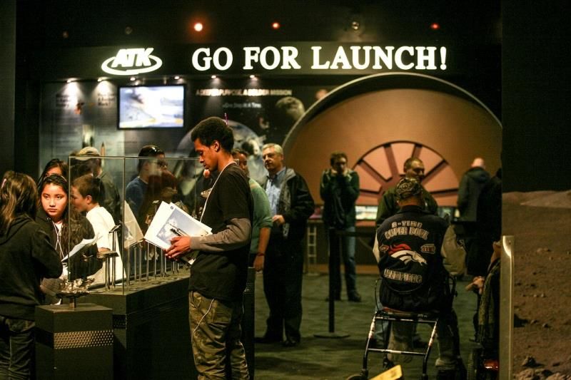
Contents

    Abstract ............................................................................................................................... 2

    1 Introduction .................................................................................................................... 6

    3 Literary Review ............................................................................................................. 9

    4 Methodology ................................................................................................................ 15

       4.1      Formulation of Goals ........................................................................................... 15

       4.2      Exhibit Design ...................................................................................................... 15

           4.2.1 Control Stations ................................................................................................ 15

       4.3      Concept Rover ...................................................................................................... 16

           4.1.1      Design Requirements ..................................................................................... 17

           4.1.2      Mechanical..................................................................................................... 19

           4.1.3      Electronics ..................................................................................................... 23

    5 Progress Report ............................................................................................................ 27

       5.1      Rover Physical Prototype ..................................................................................... 28

           5.1.1      Implementation Modifications ...................................................................... 30

           5.1.2      Mechanical..................................................................................................... 31

           5.1.3      Electronics ..................................................................................................... 34

           5.1.4      Control Software............................................................................................ 36

       5.2      Exhibit .................................................................................................................. 37

           5.2.1      Game Designs ................................................................................................ 38

                                                                  3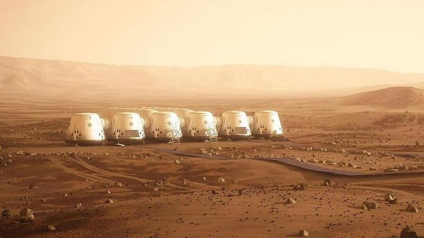
5.2.2      Phobos Mission Control Center ..................................................................... 41

      5.2.3      Proposed Exhibit Layout ............................................................................... 42

6 Recommendations .......................................................................................................... 44

7 Bibliography .................................................................................................................. 45

8 Appendix ........................................................................................................................ 46

Figure 1: Mars Foundation Goals ....................................................................................... 7

Figure 2: Hillside Settlement Proposed Design ................................................................ 10

Figure 3: Model of Opportunity........................................................................................ 12

Figure 4: The photo exhibition of 10 years on Mars ........................................................ 12

Figure 5: ATK-NASA....................................................................................................... 13

Figure 6: ATK-NASA....................................................................................................... 13

Figure 7: Mars One Settlement ......................................................................................... 14

Figure 8: Rover Concept Design....................................................................................... 16

Figure 11: Prototype Rover Custom Shield Render ......................................................... 34

Figure 12: Prototype Rover Control Program GUI........................................................... 36

Figure 13: Prototype Rover Shield PCB - Schematic 1 .................................................... 46

Figure 14: Prototype Rover Shield PCB - Schematic 2 .................................................... 47

Figure 15: Prototype Rover Shield PCB - Schematic 3 .................................................... 48

Figure 16: Prototype Rover Shield PCB - Schematic 4 .................................................... 49

Figure 17: Prototype Rover Shield PCB - Top Copper Layout ........................................ 50

Figure 18: Prototype Rover Shield PCB - Bottom Copper Layout .................................. 51

                                                            4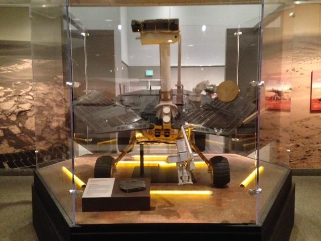
Figure 19: Prototype Rover Shield PCB - Top Silk Screen .............................................. 52

Figure 20: Prototype Rover Shield PCB - Bottom Silk Screen ........................................ 53

Figure 21: Prototype Rover Shield PCB - Top Pad Master .............................................. 54

Figure 22: Prototype Rover Shield PCB - Bottom Pad Master ........................................ 55

Figure 23: Prototype Rover Shield PCB - Bill of Materials ............................................. 56

                                               5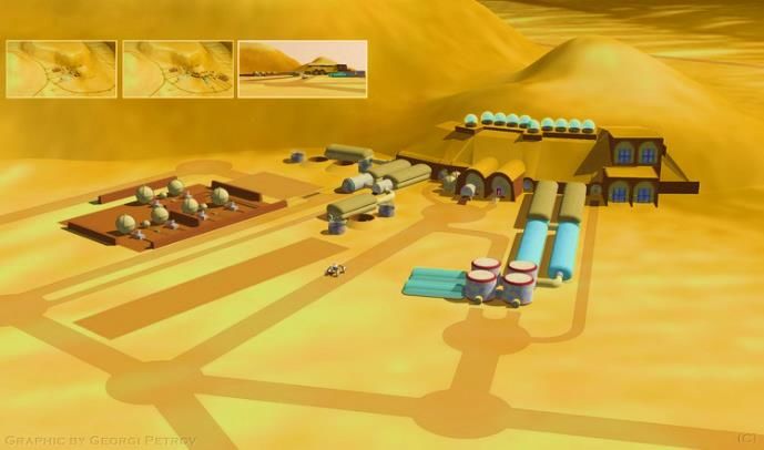
1 Introduction

       The next frontier for human settlement rather than exploration or simple resource

extraction is probably Mars. The case for a moon base is grounded in economics, but Mars

settlement would open a new era for humanity. The Mars Foundation is concerned with

promoting the habitation of Mars through manned settlement missions that are by definition one

way trips. This goal is an important landmark in technological development and human

expansion. It represents the foundation of a new age of human expansion and a safety net for

humanity as a species.

       In trying to achieve this goal, the Mars Foundation coordinates a number of projects

focused on both building public support for Mars settlement and the gathering of planning

resources and research assessing alternative approaches to a successful mission that would

launch this settlement project. This project falls under the former category, attempting to

improve the long-run public perception of Mars missions. In short we are to convince the next

generation that such a mission is possible and that the risks are acceptably low for the first wave

of colonists to arrive. They will not have the ability to return to Earth immediately so if they fail

they will die. This possibility is a major impediment to political and economic support for the

attempt. The Phobos scenario is an effort to reduce both the actual risks faced by the first

construction teams and massively impact the perceived safety of the mission. Our job is to figure

out how the next generation will learn about his exciting possibility in an engaging way that is

educational as well as informative so that at least the planning process can begin in the next

decade.

                                                  6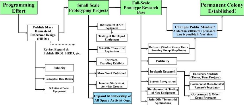
Figure 1: Mars Foundation Goals

       In general, the public is wary of any efforts to develop a manned mission to Mars. Most

people doubt the feasibility of such a mission. As long as human settlement of Mars remains as a

figment of science fiction in the public eye, the lack of necessary funding and support will ensure

it remains just that. To make this vision a reality, steps must be taken to educate the public on the

enabling technologies, both in development and already existent that make a mission to Mars in

the next decade possible.

       As it stands, it is impossible to change the minds of the average US voter on Mars policy.

In general, adults tend to have formed their opinions on this topic already and are not easy to

sway even with compelling evidence. The best alternative is to work on educating the next

generation of society’s decision makers. Looking at a younger demographic allows for evidence

to be presented and judged by more open minds. By providing unbiased information on enabling

technologies and building interest in space development, the goal is to make the importance and

possibility of Mars development self-evident without delivering the message as directly.

                                                   7
The Mars Foundation already puts on or sponsors infrequent educational events for

school children, but hasn’t looked yet at a way of standardizing and distributing a program for

Mars education. Ideas for a large facility, a cross between a museum and theme park already

exist. The approach of a smaller exhibit that could be reproduced or moved around to attain

greater coverage had yet to be examined, and doing so became our mission.

       This project team will examine the idea of a smaller more versatile exhibit for promoting

Mars settlement. By creating an experience specifically tailored for a younger demographic, this

research should present the Mars Foundation with a more effective, time and cost efficient

method of proliferating information on Martian settlement technologies and plans. Much of the

research involves the creation of prototypes for an interactive experience designed to more fully

engage the viewer. Some of the research conducted was done with local school children. Existing

museum exhibits are examined and analyzed for efficacy in communicating information and the

amount of interest they are capable of generating. Feedback was also sought in a professional

setting at the Young Professional, Student, and Educator (YPSE) 2013 conference oft held by

Region 1 of the AIAA at Johns Hopkins’ APL, in Laurel Maryland.

       By gathering data from these sources and using the knowledge and experience of Mars

Foundation founder and liaison for this project, Bruce Mackenzie, a way of providing an

engaging educational experience was developed. The final outcome of the project is the

development of a set of plans for creating an exhibit based around the core idea of a Mars base

construction simulation. These plans are flexible in that they have provisions for both highly

funded and limited to non-funded approaches to obtaining an exhibit. Additionally, a prototype

model rover was also delivered along with interface software. This is the basis around which the

exhibit plans revolve. Alternate uses for this rover and software as an educational and

                                                8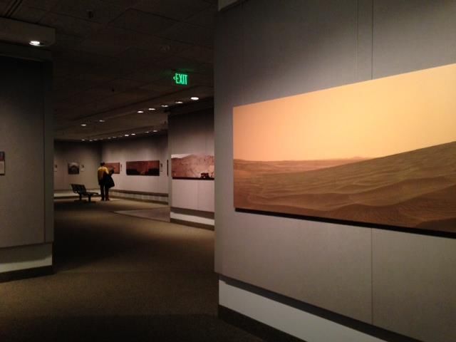
promotional aid for Mars settlement have also been explored and are detailed herein. It may be

of general utility for other science exhibits designed for this age group as well.

3 Literary Review

       Since Spirit and Opportunity landed on Mars, something like human presence has been

on Mars via robotic rovers over the last ten years. Because of the exploration done in these ten

years, now Mars is not quite as strange and unimaginable for both the public and the scientific

community. In the meantime, plenty of major discoveries on this planet has been exhibited to the

public in this last decade. For our exhibit, we took note of several different kind of projects and

space exhibitions developed in the past ten years. We even sent team members to see how this is

handled at the National Air and Space Museum in Washington DC.

       Mars Homestead Project

       First and foremost, Mars foundation’s Mars Homestead Project is one of the first to

declare that. “The mission of the Mars Homestead Project is to design, fund, build and operate

the first permanent settlement on Mars”.

       The initial goal for the Mars Homestead Project is to identify the core technologies

needed for an economical, expandable Mars Base built primarily with local materials. Efforts

will then be focused on prototype projects of increasing sophistication. These could include the

selection of existing equipment which could be used on Mars, or the construction of prototypes

of new equipment. These steps will lead the Mars Foundation to the establishment of an entire

simulated Mars settlement at a location here on Earth, which will serve as a research and

outreach center.

                                                  9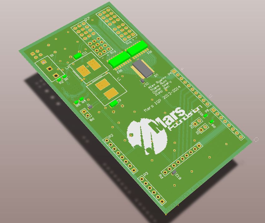
The initial programming feasibility study has been conducted by a small Program Team,

whose members have professional or academic experience in applicable engineering areas. Areas

of expertise include: Materials, Structures, Mechanical Systems, Architecture, Agriculture,

Nutrition, Process/PSSS, Electrical Systems, I&C, Data/Telecom, EHS, IE, Mars

Geology/Topography, Space Transportation, Spacesuits, Systems Integration, and many others.

       The Mars Foundation has also established a small board of technical advisors who

provide expertise in specific areas, and created a general "brainstorming" discussion group which

is open to the interested public, regardless of their level of technical experience.

       Some locally derived materials have been examined for initial settlement construction.

These materials include locally produced fiberglass - wound on site, metals, masonry - either for

un-pressurized shelter or covered with regolith to hold the pressure, polyethylene & other

polymers made from ethylene from the CO2 atmosphere, and any plant products - especially if a

byproduct of food growth. The MHP team continues to evaluate these options as well as a

number of potential alternatives.” - marsfoundation.org

                              Figure 2: Hillside Settlement Proposed Design
                                                  10
10 Years on Mars Exhibition
On the night of Jan 3rd, 2004, the rover Spirit landed on the Mars. It was followed by its
twin, Opportunity, three weeks later. At first, these two robots were expected to explore this
strange planet for about three months. One of their most important goals was find the evidence of
past water activity on the Mars. Startlingly, both rovers have found a lot of evidence along these
lines, which far exceeded the expectations of their creators. . In 2010, Spirit got stuck in a sand
trap and after dragging one inoperable wheel for a while it was declared completely dead in
2011. However, Opportunity still operates now and has showed no signs that it will soon slow
down.
"Opportunity is still in excellent health for a vehicle of its age," mission project manager
John Callas, of NASA's Jet Propulsion Laboratory in Pasadena, Calif., said in a statement. "The
biggest science may still be ahead of us, even after 10 years of exploration."
This Museum exhibition highlighted the accomplishments of these two rovers by a set of
photos which were taken by the cameras on these rovers.
"This set of spectacular images captures the beauty of Mars while telling the amazing
stories of Spirit and Opportunity as they explored water-related deposits," John Grant,
supervisory geologist in the museum’s Center for Earth and Planetary Studies and chair of the
rover mission's science operations working group, said in a statement.
11Figure 3: Model of Opportunity
Figure 4: The photo exhibition of 10 years on Mars
12ATK-NASA Exhibition
In this exhibition, WTK teamed up with NASA to exhibit and educate people about what
the next step of deep space exploration of Mars looks like. Which has some common with our
exhibition.
Figure 5: ATK-NASA
Figure 6: ATK-NASA
13In this exhibition, lots of space science and NASA’s future plan of deep space
exploration had been presented more to teach children and teenagers deep space exploration is
within their reach than to convey any particular facts to them... "I learned that the rocket can't
keep on burning unless the booster is attached," Leger said, noting the most interesting thing he
learned at the exhibit.
Mars One
Mars one is another project could not be ignored despite an amateurish technical base. It
is a Dutch company that announced plans last year to establish the first human settlement on the
Mars in 10 years. Thousands of people volunteered to go as part of the first wave of settlers
Figure 7: Mars One Settlement
In this project, Mars One wanted pick travelers to involve in a full-time training program
which included a one-way ticket to Mars. Mars One founders Bas Landsorp and Arno Wielders,
both of them previously employed in technology and space industries, declared that Mars One
14planned to send probes and robotic rover in early 2016 to set the stage for habitation of the red
planet.
4 Methodology
4.1 Formulation of Goals
The initial goals for this project were somewhat removed from the final results.
Significant time was taken in deciding the ultimate goal of this project. Deliberations on this
front happened as a collaboration of the team, the advisor, and the sponsor. The final goals and
deliverables for the project are a product of an ideal and the time constraints and resource
limitations under which the project needed to operate.
4.2 Exhibit Design
4.2.1 Control Stations
The control station was envisioned to replicate that of a small control booth. Each station
would have room for two occupants, “Controllers”, to control a single rover at a time; one person
would act as the “Driver”, while another would act as an “Operator”. A broad control panel,
approximately 5 feet long by one to one and a half feet deep, would house the majority of the
available controls. A large touchscreen, surrounded by two joysticks for both Controllers, would
serve as the primary control inputs.
This method of input was decided upon as the broad majority of the population in the
United States has had exposure to both joysticks of some sort (including arcade style ones), and
even more importantly, touch screens, such as those found on common smartphones.
15A minimum of two widescreen monitors would be used for a display output from each
control station PC, one located in front of each Controller. The software running on the PC
would automatically fill the monitors with relevant information about the faux base, the
construction rover and base status, and display camera feeds, both real and virtual, from the
rovers, base and satellites.
4.3 Concept Rover
As part of the exhibit development portion, a rover concept design was created. The
overall goal of the rover design is to create an interactive component of the exhibit. This was
decided as to increase the entertainment value, and thus the impact-ability and memorability, of
the exhibit to all museum-goers. This design concept includes several items, including the
electronic control system, mechanical construction and interactions, and the mission control
station for users to interact with.
Figure 8: Rover Concept Design
16Several suggestions and items that could be modified to more aptly suit a given
museum/environment setting were devised and considered during the development of the
concept design, and will be mentioned to allow for future examination and modification.
The conceptualized rover design is that of a utility vehicle for a Mars Settlement under-
construction and partially operational. The direct role it plays in the exhibit is explained in more
detail in section X (exhibit).
4.1.1 Design Requirements
One key requirement that was decided early in the project was that the ability of young
members of the public to interact in a meaningful way with the exhibit was essential. The
purpose of this was so that, one, it would better help achieve the primary purpose of the exhibit –
that is, to help convince the younger public that it is possible to live and settle on Mars within a
generation. The exhibit would do this by being something that they would be able to manipulate
and have an interactive experience with, and thus remain interested in for a long period of time
while at the exhibit’s location. It also had to be meaningful to watch someone else operate on
the exhibit, while waiting for his or her turn, due to natural limits with how many people can use
the exhibit at once.
This leads to the second reason: by creating an interactive exhibit that can capture the
public’s attention span for a longer period of time than a typical display, there is time to deliver
and more complete and complex message than a sound bite. One is trying to give people an
impression of a feasible Mars settlement with more than superficial and glossy pictures. The goal
17is a demonstration that provokes more thought about the topic, leaving one with some answers
and more questions to engage the curiosity and creative problem solving of the 10% of the
population that is more informed opinion leaders with substantial influence on public perceptions
and opinion.
As a result, the primary task of the project could be stated and a list of requirements
created to guide the design process that would shape the exhibit rover concept. Requirements
ranged from being mandatory, to very important, to being a nice addition if possible (See Table
1). A guiding force that had to be followed was the mandate of our sponsor, the Mars
Foundation, and their goal to promote interest in the younger generation to create a permanent
settlement on Mars. Items that might detract from the experience of promoting this interest were
ruled out as unwise. Foremost among these were things that might stretch credibility and raise
questions about the near term feasibility of what was depicted. For example, the technical design
IQP team had envisioned using a space tether to drop the Phobos base into place. Although this
is an intriguing design as an engineer, and experts would likely agree that it could be done within
the next ten to twenty years, it would be difficult to depict that in an exhibit. Also, our audience
was the general public. It could seem far-fetched to them, a scenario we are aiming to avoid.
18Requirement Priority Level Comments
Ease of use Very High Basic functionality mastered
within a minute of use
Realistic High Approximate the aesthetics and
utility of actual NASA designs as much
as possible to prevent a “Sci-Fi” feel.
Control Flexibility Medium The system needs to be able to
adapter to the approximate skill levels
and learning speeds of those using the
exhibit very quickly
Table 1: Exhibit Development Priority List
4.1.2 Mechanical
A central component of the exhibit is the miniature, yet functional Mars rover. It was
determined early in the design phase that the rover would be between 8 and 16 inches long, due
to cost constraints and the size limitations of the overall exhibit. The design process was guided
by two main priorities; these are scaled functionality, and a technically realistic physical
appearance.
Mechanical Design
Several different mechanical layouts were considered, however most of them were
deemed unacceptable for reasons including a lack of robustness, difficulty to manufacture, and a
layout that caused the rover to be difficult to drive for younger children. The rover's mechanical
19design can be broken down into five main sub-components. These are the steering mechanism,
the wheels, the suspension, the chassis, and the arm.
Steering
The first choice for a steering arrangement was a holonomic platform, where each of the
four powered drive wheels (mounted to the chassis in a rectangular profile) were connected to a
separate motorized swivel mount. This is very similar to the wheel layout for real-world rovers,
such as NASA’s Spirit and Opportunity, so realism in terms of current technology is preserved.
On Mars where there is an atmosphere flying robots and windmills would be possible, but the
public would consider that fanciful. Something like a current Mars rover is believable and
appropriate to the modest construction and assembly job to be depicted. One wants to keep it
interesting and deliver some surprises so the task is not too mundane, but credibility is of the
greatest importance, as this is not a video game.
Figure 9: Rover Steering Design
20Using a computer algorithm, steering can be simplified to take only forwards, backwards,
right, and left as control inputs. This makes control and movement of the rover easy to learn for
even very inexperienced drivers, while satisfying the mechanical interest and curiosity of more
sophisticated (older) drivers. It will also avoid problems for those with less hand-eye
coordination and abilities.
Wheels
The wheels were designed to appear reminiscent of the wheels found on current real Mars
rovers, with spokes forming the inner geometry, and an angled, treaded external circumference.
Since the steering mechanism would twist the wheels about an axis perpendicular to the ground,
the wheels were designed to be narrower proportionately than real rover wheels, so as to avoid
too much skid-friction.
Figure 10: Rover Wheel Design
21Chassis and Suspension
To handle the “harsh terrain” within the exhibit, the rover was designed with a “rocker-
bogie” linkage in the suspension, allowing the rover to flex and move over rocks and “craters”.
The chassis of the rover is kept level relative to the ground plane through the use of four
extension springs. On rovers such as NASA’s Spirit, there are multiple pairs of rocker-bogie
suspensions, but for the reason of scalability, the exhibit rover was designed with one pair [3].
However, this is not unrealistic, as a rover used in a Mars settlement would be more
reminiscent of a utility truck, and the site would be selected to be relatively free of obstacles and
then further smoothed before assembly was undertaken.
Figure 11: Rover Concept Design
It was decided that the rover should be modular and thus able to accommodate a
variety of appendages and sensing equipment. Hence, the chassis was designed to be slightly
larger than required, and was outfitted with multiple redundant mounting points to promote
future expansion and flexibility. The battery holder towards the rear of the chassis was designed
22to hold both 7.2 Volt and 9.6 Volt batteries, so that new components requiring additional power
beyond our needs could be accommodated. Because the exact size and layout of the electronic
control system was not known at the time this design decision was made, an undercarriage was
designed that could hold a microcontroller up to 4.5” by 7”.
Arm
For the rover to be effective in assembly applications and generally useful, it must be able
to manipulate its environment in some way. Manipulation and arrangement of the model
“habitation pods”, was going to be the first activity depicted. It had to do this well, but not be
limited to this activity. We decided on a small, servo-actuated fork-lift which was implemented
using an acrylic bar and a return-spring. This was placed directly on the front-center of the rover,
and is capable of lifting one end of a pod and dragging it to its target location.
4.1.3 Electronics
Figure 12: Rover Electronics Functional Diagram
23The concept rover will have an onboard computer. It is imagined that this will be a semi-
custom solution in a finished exhibit. The computer would consist of one of the many
microcomputers available today for embedded DIY projects, such as the Raspberry Pi, Gumstix
or BeagleBone (picture) –Choosing one of these for the computer would greatly cut down design
costs. It is an immense advantage if no effort has to be expended on hardware design for a
microprocessor and other related components. A “Shield” would be added to help the computer
interface with the rest of the rover electronics on-board, including batteries, actuators and
sensors. This shield could be either custom-designed, or one of the many commercially available
models that can easily be adapted. The rover computer would have software written for it to
interface with and control all on-board actuators and sensors. The use of a full “computer” with
an operating system (OS) simplifies the work to be done connecting the networking control with
the control station. It also provides ample processing power for all features that may be added to
the robot on top of what is described in this report. Then the developer of the exhibit can
completely abstract away (hide) all complex operations of the rover from the exhibit patrons that
view, operate and interact in other ways with the rover.
The computer will connect via IEEE 802.11 (commonly known as Wi-Fi) to a local
access point and router. The connection would provide a means of having the control station for
the rover communicate back and forth, enabling control of the rover, as well as transmission of
sensor data to the station. This information may be displayed to people viewing the exhibit, after
being put in a viewable format by the control station. All of this capability would be added via
the software run on the computer, making it infinitely modifiable. While the use of another
wireless standard is certainly feasible, if the rover computer can handle wireless networking
24easily with the help of the OS involved (such as Linux), it would save development time to stick
with Wi-Fi.
In order to preserve realism given that on Phobos one would actually see what was going
on primarily through the “eye” of the rover, at least one remotely-viewable camera should be
included, possibly two or more if there is adequate funding for the design and purchase of the
equipment. The camera would provide a viewpoint from the rover directly, similar to current
exploratory rovers such as Curiosity and Opportunity used by NASA currently. However, this is
a construction vehicle, and ideally one would like to be able to monitor the rover in action from a
nearby, separate vantage point while building the Mars base. While this could be done by
another rover in the same vicinity, it would be better to have the rover deploy or pass by a
camera in a viewing position on a tripod that can pan by swiveling but has a fairly limited
movement capability. If the rover can move this stand around it the camera mount does not need
to be more capable or flexible than the one commonly seen in department stores concerned about
shoplifting. .
Numerous physical and virtual sensor ideas, in addition to actuators, have been
considered possible add-ons, intended to add a level of complexity and realism to the exhibit
rovers. The physical sensors can be added onto the rover construction, and used to provide some
feedback about the rover’s operation and the environment to the human controllers at the control
station. The actual information supplied can be modified based on the written control station
software, and tailored to specific venues or audiences (e.g. a reduction in complexity if it is being
transported to a fifth-grade school demo, while trending towards a more realistic view when
deployed in a museum that serves college students and other adults). Virtual sensors would exist
25solely in the control station software, and emulate things like atmospheric conditions on the
surface of Mars, which cannot be modeled based on real data from a rover in an exhibit.
Physical Sensors
IR/Laser Distance sensors Can be used to generate a virtual
map of the rover surroundings to augment
the camera and provide sight at angles the
camera cannot reach – this can be displayed
on the control station for those interested
Wheel torque and speed feedback Can be used to provide closed-loop
(motor current and wheel encoders) feedback for motion, enabling movements to
accurately follow the desires of the
controller. Also may be used to indicate
heavy-load conditions while pulling or on
slopes.
Accelerometer, Gyroscope and Can be used to display a consistent
Magnetometer in an Inertial Measurement heading of the rover to the controller,
Unit (IMU) similar to an airplanes attitude indicator.
Note that the magnetometer would have to
be “modified” to work on Mars.
Ambient Light Conditions Indicates the current lighting and
(including visible, infrared and ultraviolet) radiation conditions on the surface,
26including non-visible spectra. This can also
be made into a purely virtual sensor.
Table 2: Rover Physical Sensor Proposal List
Virtual sensors
Sediment Tester “Tests” the soil at the rover for
potentially resourceful minerals and
elements, such as iron content.
Atmosphere Tester Reports the current atmospheric
conditions on Mars to the control station,
including temperature, pressure and gas
content.
Table 3: Rover Virtual Sensor Proposal List
5 Progress Report
A summary description of what this project produced as a deliverable to the sponsor
reveals that it consists primarily of a vision backed by a set of plans for creating an interactive
exhibit. The elements of the plan s include contingency plans that are appropriate to a low, high
and ideal funding level. Since we do not envision there being only one version of this exhibit
nationwide all three may be implemented somewhere. After hearing of our concept and the
YPSE meeting, a member of the audience on the board of a discovery center offered an
invitation to communicate further with the staff of a Maryland based science education
organization. The Mars Foundation already has a list of New England institutions that might be
27an appropriate venues. These are said to differ substantially in terms of available funding and
ability to fund raise. . In any situation the exhibit plans revolve around three main and two
peripheral components: the central activity revolving around controlling a simulated Martian
base building robot; corollary exhibit displays; basic educational materials connecting the exhibit
to educational goals of interest to teachers running a 5th or 8th grade class field trip and
promotional materials, i.e. posters and signage.
5.1 Rover Physical Prototype
The exhibit utility rover is the element of the display that we took beyond paper plan to a
working prototype, when put to the test in practice, it met nearly all of the design requirements
outlined in Section 4.2.2. The most important design parameter adhered to was the maintenance
of current conceptions of realism while exhibiting practical functionality (i.e. it does not look
overly futuristic). Early in the project, a decision was made to attempt to implement a portion of
the exhibit as a prototype, in order to get some feedback data during a demonstration of the
prototype from a suitable audience of teachers, students or discovery center staff on the appeal
and effectiveness of our designs. Candidly we were concerned that the activity could be too
mundane, that audiences would see it as little more than a remote controlled vehicle connecting
tubes in a mock landscape. Unless the imagination necessary to make this activity serve as a
proper depiction of a monumental and unprecedented moment in human history could be evoked,
it would not hold their interest. It was projected that the imaginations of the 10-15 year old
children would enable a suspension of reality that put them in a faraway place at another point in
time, if we gave them just a bit of help in maintaining the illusion. However, due to the high
28potential cost of a full exhibit, we felt the need to test that notion in some way, so as to avoid
producing a boring activity at the cost of considerable time and effort.
Due to resource and time constraints, only a portion of the complete design could be
constructed, and you can guess what part a group of robotics majors would consider the most
interesting part. However, to do otherwise would have wasted our expertise doing things liberal
arts major might do as well or better. So it was the rover that was constructed and taken to the
point of a 3rd generation prototype since several modifications were made after the original
attempt and then practical changes were made to reduce complexity and construction costs. It
also had to be feasible to construct within the time, budget and tooling available to us. As such,
the constructed prototype could be described as bare-bones – it has only a few of the planned
features available on it, but it still does provide a good indicator of how the design concept will
work in a finished setting and helps sponsors, potential funders and users to envision the
possibilities. Since other examples of the rest of the elements exist, it also helps make the case
that this can be done at a reasonable cost by removing one of the larger uncertainties requiring a
relatively rare and expensive skill set.
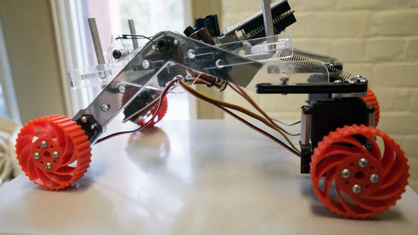
295.1.1 Implementation Modifications
Figure 13: Current Rover Prototype
One of the many modifications that had to be made was the reduction in the number of
available sensors and actuators that could be operated with during a demonstration of the
prototype. The front wheel servos that enable the swivel of the wheel were removed due to a lack
of available high-torque TowerPro MG995 servos [2]. A consequence is that the holonomic
capability (near omnidirectional motion) was removed. However, with the rear wheels
maintaining a swivel capability, the ability to turn was not impacted in a significant way.
In order to simplify development of the software and the shield, an Arduino was used in
place of the micro-computer. A consequence is that the prototype software also will not be easily
upgradeable in the future without a complete redesign, but it did enable the team to complete a
rover and deliver it to the Mars Foundation for demonstrations that be scheduled immediately.
305.1.2 Mechanical
The rover's final mechanical layout was a carefully chosen compromise between expense,
robustness, realism, and practicality. Some unforeseen problems were encountered during the
manufacturing and assembly process, but did not greatly slow down the process due to the ready
availability of laser-cutting and 3D-printing resources at WPI.
Steering
The final choice was a pseudo-holonomic platform, where the two real wheels were
connected to a separate motorized swivel mount, and the front two powered wheels were
mounted rigidly on their respective rocker-bogie arms. This was done due to initial problems
getting the front swivels to maintain structural integrity when encountering obstacles in the
rover’s path. This does not remove the ability to turn nearly on-point however, as the rear
swivels are capable of orienting the driving wheels such that when powered they cause the entire
rover to rotate in place. This feature maintained the original desired simple control system while
reducing the number of anticipated mechanical failure modes.
Wheels
The final rover wheels were 3D printed for three reasons:
1) Creating the desired wheel geometry using a material such as aluminum or brass
would have required access to a 5-axis CNC mill, a resource that was not available at the time.
2) It is a good demonstration to students of the usability of 3D-printed objects in real-
world applications. We were claiming that we were going to have robots and 3D printers make
more robots and 3D printers, and we wanted to be able to reconfigure the robots. One likely
change would be to replace the wheels as the rover is sent different places to do different things.
313) It increases the independent ability to replicate the rover, allowing it to be reproduced
and used by organizations and individuals elsewhere.
The wheel hubs were designed to that they could be easily mounted to a readily available
off-the-shelf RC servo aluminum mounting hub using 8/32 bolts. Although the wheels exhibit
low friction when used on surfaces such as table-tops and wood floors, they function similarly to
their full-size counterparts when used on granular and textured surfaces (e.g. sand, carpet, etc.).
It is possible to affix rubber treads to the wheels so that optimal operation is possible on all
surfaces.
Chassis and Suspension
The rocker-bogie suspension was laser cut from ¼” black acrylic and worked exactly as
planned. Each side consisted of two “arms” that were connected to a central pivot point with an
underside angle between them of 140 degrees. The pivot point was created using a ⅜” threaded
rod. The main chassis of the rover was kept level with respect to the arms through the use of four
extension springs placed at each corner of its rectangular base. This enabled the rover to move
and pivot to accommodate the obstacles it encountered in a manner visually identical to that of
the real-world rovers. The base of each arm was affixed with a perpendicular acetal plastic plate
to which the swivel and drive servos could be attached. Initially, problems with arm
misalignment were encountered, but were rectified by using a pair of brass bushings at the arm
pivots to reduce friction.
The chassis was laser cut from ⅜” clear acrylic, and was designed as a trussed
structure to minimize weight. Because it was known that the addition of a wireless camera may
be possible in the future, the width was increased by 1” and the length by 2”. The battery bay
was placed on the underside because the rover’s center of gravity would be too high with the
32placement of a pan-and-tilt wireless camera. Three-dimensional geometry for the chassis was
achieved by placing the planar acrylic components at right-angles to each other by a system of
square slots and steel hex standoffs. The mounting location for the control electronics was placed
on the underside of the “solar panel” (which also functions as a protective cover for the rover’s
inner workings) to save room and to give the electronics an air gap to prevent overheating.
Arm
The arm of the rover was created using aluminum angle stock and ⅜” acrylic, and was
placed in the location as originally designed. However, it was realized that the actuator servo
would interfere with the placement of the camera, so it was moved towards the back of the
chassis, and transmitted torque to the arm using a cable and spring return. Additionally, a spring
was placed in series with the cable so that in the case of the arm attempting to lift something too
large or becoming stuck, the spring would extend and prevent the stalling and overheating of the
servo.
335.1.3 Electronics
Figure 9: Prototype Rover Custom Shield Render
A custom Arduino shield was developed that incorporated several of the planned
capabilities from the concept rover, including power management, servo control, and wireless
communication.
A PCA9685 IC was added to perform servo control functionality. It communicated via
the I2C bus standard with the Arduino, and automatically handled providing control signals to up
34to 16 connected servos (only 7 channels were used on the prototype). Overload and reverse
polarity protection were added in case wires were connected improperly in future use, to prevent
most damage to the electronics.
As the Arduino does not have any built-in networking capability (and thus unable to
natively communicate wirelessly to the control station), an Adafruit CC3000 Wi-fi module was
purchased and installed. Combined with a software library for the Arduino, it provided an easy
link to the prototype control station by connecting to a Wi-Fi router and transceiving UDP
packets for control commands and status updates.
(Insert CC3000 Wifi module breakout picture from Adafruit)
Additionally, power regulation circuitry was added in the form of a Linear Technology
buck-converter IC. It provides power regulation to all components on the board, except for the
Arduino, which has its own regulator circuitry. This enables nearly any common hobby RC
battery, such as 2, 3 or 4-cell lithium-ion or lithium polymer (Li-Ion or Li-Po) batteries to be
used to power the rover.
For testing purposes, a cheap Wi-Fi webcam was purchased. It is the Easy-N M136
model, running on a 5V power supply provided directly from the rover shield power supply.
After configuration, it will connect to the same access point that the CC3000 Wi-Fi module will
connect to, providing a connection straight to the computer station.
The appendix contains a full set of reference schematics.
355.1.4 Control Software
The prototype rover control software was written in the Processing Language, a version
of Java. This was chosen due to its natural abundance of libraries for the networking, graphics
and joystick applications. Due to time constraints with the project, it was created with the intent
in mind of being easily modifiable by another programming party, while lacking nearly all
aesthetic additions that would make the Mars Utility Rover Control Station concept more like a
finished piece of software.
Figure 10: Prototype Rover Control Program GUI
The prototype rover program works by connecting to a common wireless access point
(Wireless AP), such as a router, which is shared with the rover. It starts sending broadcast UDP
messages, a common IP communication method, to the rover, checking whether it is connected
36yet or not. Once both endpoints are connected, the rover consistently sends feedback data packets
with the rover’s status, indicating to the program that it is alive. Additionally, the program sends
short UDP packets extremely fast to the rover containing commands to update its actuator
systems for driving and pod management.
A joystick connected to the computer is monitored for use as an input device, controlling
the actions of the rover. The program interprets the joysticks current angle of tilt as the desired
direction the controller wants the rover to go, maps the direction into servo commands for the
rover’s wheels, and sends the commands over the wireless interface described immediately
before. A series of button presses is interpreted for controlling the claw that grabs and releases
base pods.
5.2 Exhibit
The central focus of exhibit based off of these plans is a group activity putting a student
into the role of an astronaut building a base on Mars. Using the Phobos Scenario guidelines as
inspiration, the premise of this activity is this: “You are an astronaut on a mission to Phobos.
From this base on Phobos, you are tasked with assembling a base on the Martian surface using a
remotely operated vehicle to place habitation and infrastructure modules into an appropriate
configuration.” In this activity, the “construction vehicle” consists of a custom built miniature
remote controlled rover. Detailed plans for the construction of this rover are provided as a part of
this report. A “module” refers to a small model of a Martian habitation pod used as a game
37object in this activity. The actual activity has students operating the RC vehicle or vehicles using
a laptop with connected controls.
5.2.1 Game Designs
This “game” is a simulation primarily designed to hook student’s interest in the exhibit
overall by providing an exciting experience. Secondarily, it gives a presents a rough idea of the
requirements of a real Martian base and acts as the basis for several design activities that could
be included as part of the exhibit.
Basic Rules
The game supports a number of players proportional to the number of rovers and amount
of field space constructed. In a situation with a small playing field and only one rover, only 8
students could be occupied at a single time with activities surrounding the game.
The primary participants in this activity are the “pilots” at the controls of the rover. It is
recommended that two students operate each rover together, one controlling the rover drive and
another the camera view and manipulator arm. Another group of two students can supervise the
field as mission controllers, advising the pilots on the location of modules and other possible
problems. Additionally a group of 2 – 4 students could observe the activity and be tasked with
improving the design of the rover manipulator or wheels.
The actual objective of the game is the assembly of a functioning Mars base (in
simulation). This task requires the inclusion of certain modules. The exact requirements need to
be scaled to the final location and nature of the exhibit, but can be parameterized somewhat.
Approximately half the modules should be standard habitation modules, one quarter should be
dedicated to food production, and the remaining quarter should be some mix of life support,
workshops, manufactories, or other supplementary modules. The nature of each module will be
38clearly marked, but the actual construction will vary by budget. Details regarding the modules
are discussed in a subsequent section of the report.
Modules are queued at a production facility. Ideally this would be a large structure
representing a facility for producing modules. In a lower budget situation, the modules could
merely be stacked or laid out in rows at predetermined spot on the playing field. Modules will
have to be placed starting at another prop representing a power station or landing capsule. The
end condition of the game can be either determined by the completion of a base meeting the
already discussed criteria or with a time limit, presented as a fuel limitation of the rover.
This describes the most basic premise for the activity which can be done with limited
funding or setup. There are however, a number of other ideas that are dependent on further
funding or a permanent location these are described in the next section along with their requisite
conditions.
Extended Game Elements
1. Advanced Modules
The design of the modules with greater funding available would likely include more
complex elements. Modules can be designed to light up when attached and also provide
indication at the monitor from which the students control the rover that the module is online.
This way, the activity can be more easily controlled or automated; the computer can keep track
of the number and type of placed modules and indicate when a minimum base has been
established. This is esp. important in a museum setting as it allows the activity to run on its own
with less of a staffing requirement.
392. Improved Playing Field
Currently, the team has not developed a comprehensive plan for constructing a playing
field or tested playing surfaces. The game as it is assumes a simple flat playing surface without
ornamentation or significant terrain features. However, a better playing surface might consist of
a mockup Martian environment. Creating a plaster or concrete field with terrain elevation
features, sand pits, and valleys creates allows for creating a more interesting base and for a
greater focus on rover design. Presenting uninhabitable or non-traversable areas creates
restrictions that make the game more difficult and more enjoyable.
3. Rover Reconfiguration
With the prerequisite of an improved playing field, redesign or reconfiguration of the
current rover design presents an opportunity for another activity. In small groups of two to six,
students would be given the opportunity to analyze the performance of components of the model
rover being used by the base building activity. Specifically, the wheels, the manipulator arm, and
the steering control scheme could be presented as flawed systems and students would be
expected to brainstorm improvements. Taking this activity further would present this team of
students the opportunity to swap out the rover’s wheels, choosing from an array of prefabricated
wheels, the set that most closely resembles their desired improvements. The same could be done
for the manipulator arm. The ultimate version of this activity would allow the students to work
with a staff member to actually use 3D design software to make custom alterations and print a
new set of wheels or manipulator for the rover.
40A simpler approach to actual alteration of the rover is allowing the students to choose a
new steering control scheme from a pre-produced set. This is functionality is implemented
already in the prototype version of the rover, and only needs an interface option to control it.
4. Additional Cameras
If funding and a permanent space were available, a number of camera angles could be
added to the standard rover camera included on the current design. An overhead camera view of
the field from above represents a satellite view or a view from the Phobos base and allows
students better vision of what they’re doing on the field. With even more funding this camera
could be used to provide a graphics overlay of the playing field with objectives marked out; this
would be necessary for adding other sub-objectives like mining or rescue missions to the base-
building game. Using image recognition with QR codes or other markers, the position of rovers
and modules can also be determined with this overhead camera, even allowing automated field
cleanup and making optional objectives more immersive.
A camera placed along the rover’s manipulator arm would also be ideal, letting the
students move modules around with better accuracy and providing increased realism. These
improvements are advantageous as they give the impression of technology being at appoint
where even a museum exhibit can simulate in miniature the actual functionality of a Mars
mission.
5.2.2 Phobos Mission Control Center
The control station was envisioned to replicate that of a small control booth. Each station
would have room for two occupants, “Controllers”, to control a single rover at a time; one person
41would act as the “Driver”, while another would act as an “Operator”. A broad control panel,
approximately 5 feet long by one to one and a half feet deep, would house the majority of the
available controls. A large touchscreen, surrounded by two joysticks for both Controllers, would
serve as the primary control inputs.
This method of input was decided upon as the broad majority of the population in the
United States has had exposure to both joysticks of some sort (including arcade style ones), and
even more importantly, touch screens, such as those found on common smartphones.
5.2.3 Proposed Exhibit Layout
Any exhibit following the recommended guidelines should consist of three main
components: an interactive hook/activity that draws attention and builds interest in the viewer; a
set of less engaging, more informative semi-interactive displays that keep interest through hands-
on or highly visual learning/representation of knowledge; lastly, for viewers that have been fully
hooked by the previous displays, purely informational, but visually interesting displays (i.e.
posters) that provide denser, more serious information about Martian settlement and the Phobos
scenario. The final component is more targeted towards adult viewers than students, but is meant
for viewing by both. This section describes one potential layout in detail following these
guidelines.
The majority of the exhibit is dominated by the already discussed base building
simulation. This is the centerpiece of any possible exhibit layout, around which more educational
materials and displays revolve.
42The playing field abuts the center of one wall, the background displaying a Martian
panorama. On one side lies a Phobos control station, where students pilot rovers or oversee the
“mission”. Against the other side of the playing field is a table workspace with laptops or other
materials for redesigning parts of the rover. The forward side of the playing field is empty for
viewing or access purposes. The overall shape of the field allows access by museum staff to any
part of it while standing beside it. Likely, the field would be surrounded by Plexiglas shields to
prevent tampering with the rover or modules.
Against the side walls of the exhibit there would be tables displaying supplementary
material. These provide a more educational but less interactive way of communicating
information and demonstrating enabling technologies. A concise list of possible table sub-
exhibits:
1. 3D Printing Display
A real 3D printer set to constantly but slowly produce pertinent materials, i.e. rover parts,
modules, actual parts that could be used on Mars in a habitation module, etc. The cost of
the filament to produce these parts constantly could potentially be negated by sale of the
produced parts as souvenirs at a marked up rate. This is a cheaply produced and visually
appealing display, ideal for any budget range, but better suited to a semi-permanent
location.
2. Chemical Synthesis
Another option for a display table is a methane generation setup, showing one of the
many chemical manufacturing processes that would be used on base.
3. Orbital Mechanics and Gravity
A display demonstration both the nature of orbits around Mars and the difference in
43You can also read