VHR IMAGE ACQUISITION CAMPAIGN 2020 - TECHNICAL GUIDANCE FOR CWRS AND FOR THE LPIS QA - EUROPA EU
←
→
Page content transcription
If your browser does not render page correctly, please read the page content below
VHR Image Acquisition Campaign
2020
                                                   Technical guidance for
                                                   CwRS and for the LPIS QA

                                                   ÅSTRAND P.J., VAJSOVA B., BREUNIG J.,
                                                   LEMAJIC S., WALCZYNSKA A., HAIN S.,

                                                   KORNHOFF A, RANKL M., FLINGELLI T.

                                                   2020

  WorldView-4 data, © EUSI/Digital GlobeTM, 2017
This publication is a Technical report by the Joint Research Centre (JRC), the European Commission’s science and knowledge
service. It aims to provide evidence-based scientific support to the European policymaking process. The scientific output
expressed does not imply a policy position of the European Commission. Neither the European Commission nor any person
acting on behalf of the Commission is responsible for the use that might be made of this publication. For information on the
methodology and quality underlying the data used in this publication for which the source is neither Eurostat nor other
Commission services, users should contact the referenced source. The designations employed and the presentation of material
on the maps do not imply the expression of any opinion whatsoever on the part of the European Union concerning the legal
status of any country, territory, city or area or of its authorities, or concerning the delimitation of its frontiers or boundaries.

Contact information
Name: Pär-Johan Åstrand
Address: Via Fermi 2749, TP272, 27b/033 I-21027 Ispra (VA), Italy
E-mail: par-johan.astrand@ec.europa.eu
Tel.: +39.0332.78.6215

EU Science Hub
https://ec.europa.eu/jrc

JRC121944

Luxembourg: Publications Office of the European Union, © European Union 2020

The reuse policy of the European Commission is implemented by the Commission Decision 2011/833/EU of 12 December 2011
on the reuse of Commission documents (OJ L 330, 14.12.2011, p. 39). Except otherwise noted, the reuse of this document is
authorised under the Creative Commons Attribution 4.0 International (CC BY 4.0) licence
(https://creativecommons.org/licenses/by/4.0/). This means that reuse is allowed provided appropriate credit is given and any
changes are indicated. For any use or reproduction of photos or other material that is not owned by the EU, permission must be
sought directly from the copyright holders.

All content © European Union

VHR profile-based specifications
 EC-JRC-D-D.5-CAPISA

  Author:   Pär Johan ÅSTRAND           Status:     V.10.9

     Co-    Blanka VAJSOVA, , Jürgen
 authors:   BREUNIG, Slavko LEMAJIC

                                       Circulati
                                       on:          Internal/Commission, MS administrations and
            Agnieszka  WALCZYNSKA,
                                                    their contractors, FW contractors
            Susanne   HAIN,  Ansgar
            KORNHOFF,       Melanie
            RANKL, Tine FLINGELLI

Approved:   Pär Johan ÅSTRAND

                                                    \\139.191.148.210\D5_capland\Projects\CAPIS
                                                    A_WP1\2019\Image_Acquistion_FWC_Delivera
    Date:   17/03/2020                  Int. ref:
                                                    bles\VHR\D.3.1_VHR_Specifications
VHR profile-based specifications
EC-JRC-D-D.5-CAPISA

Table of Contents:
1 Introduction ........................................................................................................................................................................ 10
2 Pre-image request ............................................................................................................................................................ 14
3 Data requests ..................................................................................................................................................................... 15
4 Feasibility assessment ..................................................................................................................................................... 22
5 Acquisition requests ........................................................................................................................................................ 25
6 Quick-look image upload .............................................................................................................................................. 26
7 Acquisition acceptance - validation ........................................................................................................................... 27
8 Ordering ............................................................................................................................................................................... 31
9 Delivery ................................................................................................................................................................................. 32
10 Input data quality assessment ..................................................................................................................................... 33
11 Pricing and invoicing ....................................................................................................................................................... 35
12 Image data provision to the JRC (image return) and image access ............................................................... 36
13 VHR image profiles .......................................................................................................................................................... 40
14 Quality assurance/quality control ............................................................................................................................... 45
15 Risk of satellite failure ..................................................................................................................................................... 47
16 LPIS QA image acquisition ............................................................................................................................................ 48
17 JRC responsible staff and e-mail addresses ............................................................................................................ 57
18 References ........................................................................................................................................................................... 58
19 Annexes ................................................................................................................................................................................ 61
VHR profile-based specifications
EC-JRC-D-D.5-CAPISA
List of Figures
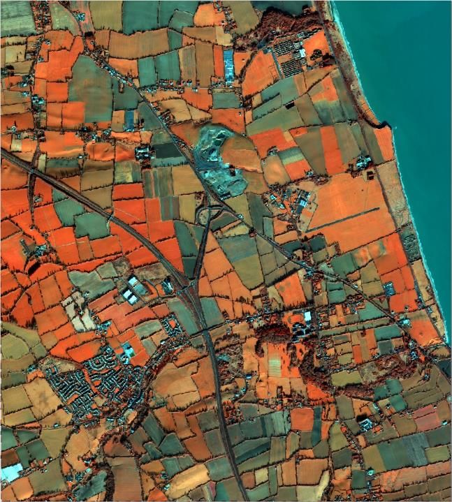
Figure 1 - The overall process of the SRS image acquisition. ......................................................... 12
Figure 2 - Explanation of difference between a proposed acquisition and a backup profile acquisition ...... 28
Figure 3 - GSD versus elevation angle for the VHR profiles .......................................................... 43
Figure 4 - Image selection from the single image strip within the same MS/LPIS system ....................... 53
Figure 5 - Left: Image selection from the single satellite pass between two different LPIS systems (two
LPIS QA zones; right : Image selection from the single satellite pass within the same LPIS system or
LPIS QA zones (two LPIS QA zones) ...................................................................................... 53
Figure 6 - Image selection from the single satellite pass between two countries (left: bad choice; right:
good choice) ................................................................................................................. 54
Figure 7 - Specific case with a group of small islands ................................................................. 55
Figure 8 - General recommendations for a buffer creation around CwRS zones .................................. 70
Figure 9 - Relation elevation angle versus off-nadir angle and some satellite angles of importance .......... 71
List of Tables
Table 1 - VHR profiles adopted within the CAP OTSCs, and the LPIS QA .......................................... 42
Table 2 - Main structure nodes ........................................................................................... 64
Table 3 - XML metadata file, values ...................................................................................... 64
Table 4 - Possible values for the sensor tag, their allowed abbreviations and their combination with
profiles ........................................................................................................................ 64
Table 5 - Possible values for MeteoFlag and their description ....................................................... 65
Table 6 - Possible values for ImageMode node and their description .............................................. 65VHR profile-based specifications
EC-JRC-D-D.5-CAPISA
Document history
Version Date Comment Author
First release includes updates of 2007 specifications (FMP 7528)
incorporating exclusion of OrbView3, changes to EROSB, changes to PA, ME, image
1.0 01/05/2008
Formosat2, inclusion of WorldView1, backup procedure changes, providers
image return, etc.
1.1 30/05/2008 Final version after draft revision deadline 30/05/08 PA
1.2 12/03/2009 Updates on GeoEye-1 Image providers
23/03/2009, Administrative routines, image return, change on EROS B and SPOT PA, ME, CA
1.31 02/04/2009, backup;
22/06/2009 Final check, minor corrections on image return, and GE1 sw suites PA
2.0 01/05/2010 New edits 2010: WV1, WV2, copyrights EUSI, PA
Update of document for the 2011 Campaign: introduction of auto-
backup; introduction of new backup approach; elevation angle
10/02/2011, restrictions; introduction of 2010 year’s edits including WV2 (ref.
3.0-3.1 PA
25/02/2011 doc. JRC IPSC/G03/C/PAR/par (2010)(11936)); introduction of the
THEOS sensor; invoicing issues; other miscellaneous issues (e.g.
sensor formats, zones: no 500/5 km rule on shapes); all edits in RED
Further updates according to EG, BW (minor clarifications, and edit
to pricing issue), updates on LioDotNet by EG (e.g. upload with
3.2 05/03/2011 shapefile, plus minor other changes); introduction of checksum by EG, BV, SG, AB
image providers and contractors to be able to check correct image
data delivery by FTP (AB)
Clarifications on data return, introduction of functional e-mail
LioDotNet, ref. THEOS FWC no., and THEOS products, elevation
angle clarifications, clarifications upon EUSI input 10/3/2011 (e.g.
3.3 13/03/2011 PA
inserted WV2 tiling options, deleted minimum width of an area of
interest (AOI), clarification on feasibility iterations, and references
on benchmarks inserted)
Grammatical edits and minor clarification on elevation angle and
3.31 17/03/2011 CA, PA
image data access
Accept of image providers: EUSI (no further input); e-GEOS (minor
corrections allowing panchromatic (PAN) to be prime upon Member
MW, BB, RN, (image
3.32 04/04/2011 State’s (MS’s) request with possible additional high resolution
providers)
(HR)/very high resolution (VHR) if requested); renumbering of
erroneously numbered chapters
New version for 2012 and future: constellation tasking, feasibility
categories; elevation angle thresholds for LPIS QA and for
hilly/mountainous control zones; no dedicated VHR backup; tiling;
4.0 20/10/2011 LioDotNet upgrades on zone definition parameters and on ordering. PA
Moreover, some chapters have been rearranged to avoid
repetitions (e.g. the sensor zone description chapter has been
moved to be with the sensor product description)
Introduction of Constellation WV2 and WV1; update on chapter on
4.1 21/11/2011 PA, BB, MW
feasibility; updates on F2, The3os products
Inputs after Tallinn Conference November 2011; e-GEOS (elevation
angle typo, on copyright text, GE1 specs, IK2 specs); EUSI
4.2 16/12/2011 PA, AO, ES
(recommendation is to keep shapes simple but no compulsory limit;
QB may be chosen as prime; QB tiling)
Updates on unit name; introduction of the new VHR sensor –
4.3 26/10/2012 Pleiades (PL1); updates on zone parameters; updates on speculative EG, BV, PA
backup; updates on licensing textVHR profile-based specifications
EC-JRC-D-D.5-CAPISA
Version Date Comment Author
Rework of document to fit the framework contract for supply of
satellite remote sensing (SRS) data and associated services in
5.0 10/02/2013 PA
support to checks within the Common Agricultural Policy (CAP) –
VHR sensor-independent profile
Edits after CID-IAT, and AB input on 5.0: roles of stakeholders; other
5.1 26/03/2013 edits on zone parameters, acquisition windows (AWs), feasibility, PA, EG, BV, ISM, AB
delivery image data return, and VHR profile sensors
Corrections for LioDotNet, and final review before outsource
5.2 26/06/2013 CW, SG, PA, CD
tendering
Corrections for changes due to the upgrade of LioDotNet to G-
6.0 03/02/2014 GDM, PA
LIO.NET
6.1 10/02/2014 Minor edits on delivery notes and finalisation of the document GDM, PA, ISM
6.2 20/02/2014 Various edits and comments by FWC VHR profile EUSI EUSI (ES, SO, AK, MW)
7.0 16/03/2014 Finalisation of Campaign 2014 specification PA
7.1 29/09/2014 Draft for improved VHR specifications 2015 EUSI
Check, acceptance and insertion of certain elements regarding Joint Research Centre
7.2 15/11/2014 iteration of specified area/shapefile/corrections; update of profiles, (JRC) (PA, JB, GDM,
and complete check of document for the 2015 Campaign BV, CW)
7.3 01/12/2014 Update of image return (provision to the JRC) JRC (PA, JB)
Update of feasibility assessment (EUSI); update of profiles (JRC) EUSI/JRC (PA, JB,
7.5 17/12/2014
GDM, BV, CW)
7.6 30/09/2015 Updates by EUSI for Campaign 2015 EUSI
4
7.7 06/10/2015 Updates for the use of G CAP; smaller textual edits JRC (GDM)
Updates by the JRC after meeting with EUSI (12/10/2015) and JRC (PA, JB, GDM, BV,
7.8 21/11/2015
AB(29/10/2015) CW)
Final version after MS administrations and their contractors input JRC (PA, JB, GDM, BV,
8.0 29/02/2016
and LPIS A5 issue update (section 12.1.3 and Table 1, p. 28) CW)
Final version after EUSI input on above, and on percentage of A5/A2
JRC (PA, JB, GDM, BV,
8.1 15/03/2016 (section 4.1.7–8); JRC edits in dense haze flag (becomes dense
CW)/EUSI
haze/snow/flood flag or MeteoFlag section 7.1.8)
JRC draft after input from EUSI as of Del. D.3.1 (17/10/2016) JRC (PA, JB, GDM, BV,
9.0 14/11/2016
CW)
JRC final check, and edits on, for example, feasibility and profiles JRC (PA, JB, GDM, BV,
9.1 13/03/2017
CW)
Delete column root mean square error to be proven in benchmark
(Table 1); and error in section 12.1.4: 75 cm. Finalisation of JRC (PA, JB, GDM, BV,
9.3 29/03/2017
feasibility section after having concluded FEASIBILITY module CW)
4
development in G CAP
Added details on buffers around zones; AComp possibility;
procedure with an exchange of letters; pre-image request chapter;
LPIS QA separate chapter; image return (source) JRC (PA, JB, GDM, BV,
9.4 17/10/2017
Update of profile characteristics, zone and AW parameters; link to CW)/EUSI
Digital Globe’s archive; copyrights (WV4 added, EROS B deleted);
references (WV4 and S2B added); XML metadata file structure
JRC (SL, PA, GDM, CW,
9.5 13/11/2017 LPIS chapter updated; invoice chapter updated
BV)
9.51 05/01/2018 Final update of section 4.1.13 on feasibility classes; removal of JRC (PA, GDM, BV, SL)
suggested additional input percentage and reduction of class 2VHR profile-based specifications
EC-JRC-D-D.5-CAPISA
Version Date Comment Author
(medium, yellow) to 70%; final update of LPIS chapter
JRC proof read
service, checked by
10.0 01/03/2018 Proof read final
JRC staff (SL, PA,
GDM, CW, BV)
through
10.1 Updates regarding LPIS, IDQA, proposed/backup use, … SL, JB, PA, BV, GDM
campaign
10.2 01/10/2018 EUSI updates after 2018 Campaign AW, EUSI team
JRC revision after Dubrovnik, 2018; sentence in feasibility chapter;
10.3 03/12/2018 Acquisition acceptance – validation mainly on backup; LPIS chapter BV, SL, PA
clarification
10.4 20/12/2019 LPIS chapter; cleanup of document after EUSI input EUSI, JRC
Edit on item 3.3.16 on ‘automatic extension flag’; review LPIS
10.5 18/01/2019 EUSI, JRC
chapter; note on WV4 chapter 15
10.6 27/09/2019 EUSI input: Maxar, K3A, search tool, LPIS … EUSI
10.7 20/10/2019 JRC: remove yellow, minor updates, K3A, LPIS JRC
10.8 08/11/2019 Final corrections JRC
3.3.16 and 4.1.13 edited for ‘automatic extensions’; and LPIS
10.9 17/03/2020 JRC
chapter 16.6.6
Authors’ initials
ACRONYM FULL NAME ORGANISATION
AK Ansgar Kornhoff EUSI
AW Agnieszka Walczynska EUSI
BV Blanka Vajsova JRC
CW Csaba Wirnhardt JRC
GDM Giovanni Di Matteo JRC
JB Juergen Breunig JRC
PA Pär Johan Åstrand JRC
SL Slavko Lemajic JRC
SO Susanne Hain EUSI
TF Tine Flingelli EUSIVHR profile-based specifications
EC-JRC-D-D.5-CAPISA
Abbreviations, acronyms and terms
Abbreviation/term Explanation
AComp Atmospheric Compensation algorithm
AOI Area of interest (e.g. a control zone)
Acquisition request; a closed AR is an AR that has one of the following
AR
statuses: Accepted/Full, Accepted/Partial or Failed
(AR) ID Identifier of an acquisition request
AW Acquisition window
CAP Common Agricultural Policy
CAPI Computer-assisted photo interpretation
CC Cloud cover
A contractor of the MS administration responsible for the CAP subsidy
diagnosis of the MS using the SRS imagery; not to be confused with
Contractor
the successful tenderer (ST) of the framework contract (FWC) signed in
[1]
CTS Common technical specifications
CwRS Control with Remote Sensing
DEM Digital elevation model
DG AGRI Directorate-General for Agriculture and Rural Development
DRA Dynamic range adjustment
EC European Commission
ECA European Court of Auditors
EFA Ecological Focus Area
EPSG European Petroleum Survey Group
EU European Union
EULA End-user licence agreement
The successful tenderer(s) who has/have been awarded an FWC with
FW contractor
the JRC as of [1] – the equivalent of IP (see below)
FWC Framework contract
G4CAP Final evolution of *LIO systems, available from August 2015VHR profile-based specifications
EC-JRC-D-D.5-CAPISA
Abbreviation/term Explanation
GAEC Good agricultural and environmental condition (CAP cross compliance)
GCP Ground control point
GIS Geographic Information System
Ground sampling distance, the nominal size of one sensor pixel
GSD
projected onto the imaged surface
HHR High High Resolution (SRS imagery)
High resolution (SRS imagery) - used also as generic term for high-
HR
resolution imagery in this document
IACS Integrated Administration and Control System (CAP)
IDQA Input Data Quality Assessment
IES Institute for Environment and Sustainability, Joint Research Centre
Image Provider, in this document, the successful FW contractor or
IP successful consortium of image providers who signed an FWC with the
JRC [1]
JRC Joint Research Centre of the European Commission
LF Landscape Feature
LioDotNet, G- JRC web-based systems for the management of image acquisitions
LIO.NET, NG-LIO.NET from 2005 to 2015
LPIS Land Parcel Identification System
LPIS QA Land Parcel Identification System Quality Assurance
MARS Monitoring Agricultural ResourceS
MD5 is one in a series of message digest algorithms; md5sum is used
MD5 (md5sum) to verify the integrity of files, as virtually any change to a file will cause
its MD5 hash to change
MS Member State
MS administrations or appointed contractors of the MS administration
MS administrations
responsible for the CAP subsidy diagnosis using the SRS imagery
(or contractors)
delivered by the JRC
MSP Multispectral
ONA Off-Nadir Angle
ORAW Originally Requested Acquisition WindowVHR profile-based specifications EC-JRC-D-D.5-CAPISA Abbreviation/term Explanation OTSC On-The-Spot Check PAN Panchromatic Pre-IR Pre-Image Request PSH Pansharpened QA Quality Assurance QC Quality Control QCR Quality Control Record QL Quick-Look, reduced resolution browse image RFV Rapid Field Visit RMSE Root mean square error RP (Agricultural) Reference Parcel SC Specific Contract SMR Statutory Management Requirement (CAP Cross Compliance) SPS Single Payment Scheme SMR Statutory Management Requirement (CAP Cross Compliance) SRS Satellite Remote Sensing SWIR Short Wavelength InfraRed UTM Universal Trasverse Mercator VHR Very High Resolution (SRS imagery) UTM Universal Transverse Mercator WGS 84 World Geodetic System 1984
VHR profile-based specifications
EC-JRC-D-D.5-CAPISA

1   Introduction

1.1 VHR image acquisition for the CAP checks programme

1.1.1   Since 1993, the Directorate-General for Agriculture and Rural Development (DG AGRI)
        has promoted the use of ‘Control with Remote Sensing’ (CwRS) as an appropriate
        control system suitable for checking whether or not aid is granted correctly. The legal
        basis of CwRS is Regulation (EC) 1306/2013 (Article 6(b), 21) and its implementing
        Regulations No 908/2014 (Article 26), No 809/2014 (Articles 24, 38, 39 and 40) and
        No 2333/2015 [2].

1.1.2   It should be mentioned that in May 2018, (EU) Regulation was further amended to
        allow for the introduction of the so called ‘checks by monitoring’. In fact, several MS
        Regions are, according to the recently adopted Article 40a of the implementing
        regulation (EU) 746/2018 of 18 May 2018 amending the Implementing Regulation
        (EU) No. 809/2014, opting to introduce an agricultural aid check system based on
        monitoring. This change will be of importance for the future CAP. The purpose of
        these specifications is however to describe the rules for the presently used CwRS for
        the On-The-Spot-Checks (OTSC), and not yet the checks by monitoring [3].

1.1.3   Financing of the CwRS imagery is in accordance with above mentioned Council
        Regulation (EU) 1306/2013 and Commission Implementation Regulation (EU)
        809/2014, 908/2014, where the Commission services are asked to centralize the
        acquisition of SRS imagery, and their free of charge supply to the MS. This
        responsibility was transferred to DG JRC in 1998. It is today managed through a co-
        delegation of signature by DG AGRI (via DG BUDG; internal ref. Ares (2015)1215220)
        to DG JRC’s D.5 Food Security Unit.

1.1.4   Regarding the timing of the operations, Commission Implementing Regulation (EU)
        No 908/2014, specifies, in Article 26:
           (a) 1.) For the purposes of Article 21 of Regulation (EU) No 1306/2013, each Member
               State shall inform the Commission by 1 November of each year at the latest, as to: (a)
               whether it wishes the Commission to acquire the satellite images necessary for its
               programme of checks and/or for its Land Parcel Identification System Quality
               Assessment; (b) the area to be checked and the number of planned control zones.
           (b) 2.) Member States requesting the Commission to obtain the satellite images shall
               finalise, in cooperation with the latter and before 15 January, following the
               communication of information referred to paragraph 1, the zones to be covered and
               the timetable for obtaining those images.
VHR profile-based specifications
EC-JRC-D-D.5-CAPISA
1.1.5 Following the real-time evaluation in 2003 and the successful operational application
since 2004, the JRC, in agreement with DG AGRI, continues to supply very high-
resolution (VHR) SRS imagery to the Member State (MS) administrations for their
CwRS for area-based subsidies.
1.1.6 Since 2010, DG AGRI has called for a yearly Land Parcel Identification System Quality
Assurance (LPIS QA). Reference is made to the legal basis for the LPIS QA, given in
Delegated Regulation (EU) No 640/2014 (Article 6). Specific VHR imagery satisfying
the technical LPIS QA recommendations, for example including specific conditions of
elevation angle and cloud cover (CC) (see section 13.2), is acquired for this purpose
(see section 3.1.2 and [3]).
1.1.7 Since the 2014 Campaign, the detailed management of VHR image acquisition – to
cover the correct areas at the correct times of the growing season required for the
CAP checks – has passed to industry to carry out within quality specifications
managed by the JRC. This choice has been made because there are several suppliers
of SRS imagery that have proven competency in supplying the JRC efficiently with the
SRS data needed for the CAP checks.
1.1.8 There may be one or more framework (FW) contractors appointed by the contracting
authority, the JRC, to perform this task. In these specifications, the image provider (IP)
therefore refers to the FW contractor, with which the JRC has signed a framework
contract (FWC) [1].
1.2 Objectives, referencing and structure of this document
1.2.1 This document defines the VHR profile-based specifications to be used within the CAP
checks programme (CwRS and LPIS QA). Its objective is to give the stakeholders 1 in
the image acquisition process clarity in the technical detail, and it describes the
process flow starting from zone definition, through image use, to image return and
possible re-use of imagery at the end of the Campaign (see Figure 1).
1.2.2 The JRC has an overarching role as responsible for the functioning of the FWCs and
for the quality control (QC) of the operations, while most of the interaction necessary
within the image acquisition process takes place between the FW contractor and the
MS administrations (or contractors) performing the CAP checks. These specifications
are intended also to describe these interactions.
1.2.3 This document is available in the ‘Documentation’ section of the G 4CAP Web
application [4].
1
The stakeholders, or actors, are the JRC, DG AGRI and the FW contractor acting as IPs and operators, and the MS administrations (or their
contractor) performing the CAP checks.VHR profile-based specifications
EC-JRC-D-D.5-CAPISA
1.2.4 Several references are made here to the common technical specifications for the
remote sensing controls of area-based subsidies [5], and relevant guidance
documents found at the Monitoring Agricultural ResourceS (MARS) WikiCAP [3], to
the Guidelines for Best Practice and Quality Checking of Ortho Imagery [6] and to the
high-resolution (HR) profile-based specifications [7], which should be used in
conjunction with the present document. Reference is also made to the terms and
conditions of the FWCs for image procurement with the JRC [1].
1.2.5 Figure 1, shows the overall process of the SRS image acquisition, split into macro-
actions and coloured by the function of the type of user responsible for the single
macro-action. This document tries to follow the same flow as that shown here.
Figure 1 - The overall process of the SRS image acquisition.VHR profile-based specifications
EC-JRC-D-D.5-CAPISA
1.3 G4CAP
1.3.1 *LIO systems, which were created in 2005, 2013 and 2014 to manage the CwRS
campaigns online, were replaced in 2015 by the G4CAP system, a Web application
that is kept updated and constantly improved by the JRC to enhance the daily work of
the campaign stakeholders and in line with the CAP evolution.
1.3.2 G4CAP is the Web-based application used to manage the whole campaign workflow.
Its functionalities are described in its manual, available online at the G4CAP Website
under the ‘Documentations’ section [8]. G4CAP is also the main communication tool
between the CAP check actors during the campaign: its automatic e-mail notifications
are used to synchronise actions between different actors.
1.3.3 It is compulsory for all the stakeholders involved in the CAP checks to use G4CAP.VHR profile-based specifications
EC-JRC-D-D.5-CAPISA
2 Pre-image request
2.1.1 All MS administrations participating in the CAP checks campaign must input their
forecasted requests for imagery into the pre-image request (pre-IR) module of G4CAP
for the campaign to start. This input provides the JRC with information on:
basic on-the-spot check (OTSC) information;
basic CwRS information;
details of planned CwRS methods, with relevant justifications;
VHR/HR profile requests2 (for each type of profile; see chapter 13, and [7]).
2.1.2 In accordance with Regulation (EU) No 908/2014; Article 26 (see section1.1.4), each
MS shall finalise insertion of its pre-IR by 1st of November, before the campaign
starts.
2.1.3 Imagery will be allocated only if MS administrations justify their image choice as
needed for effective CAP checks. The JRC will use inserted information to efficiently
model image allocation. This will be done to fit established budgetary envelopes
(indices such as efficient image use and fair image cost/OTSC area are used).
2.1.4 It is strongly advised that the MS administrations refer to G4CAP online help
(information and tip-over) when the pre-IR is inserted and also refer to the
instructions given in Chapter 4: Feasibility assessment.
2.1.5 The JRC recommendation is to use one VHR AW and between one and a maximum of
three HR AWs (plus any number of Copernicus Sentinel-1/2 (S1, S2)), but exceptions
to this rule may occur: the methodology must be justifiable by the MS administrations
in the pre-IR module.
2.1.6 The JRC also recommends substituting a second VHR AW with a VHR aerial AW, or
with a fixed high high resolution (HHR) AW (setting the earliest and latest start dates
to be the same) and defining a suitable AW length (e.g. 6 weeks).
2
Special profiles may be requested by the JRC; these will allow elevation angle uplift or certain ground sampling distance (GSD)
requirements (e.g. VHR+ Topographic, or VHR_EFA_LF, etc. or 8/16 bands and pan bundle data), but MS administrations will have to
justify these options in detail; see Chapter 13.VHR profile-based specifications
EC-JRC-D-D.5-CAPISA
3 Data requests
3.1 General
3.1.1 The regulatory basis for the CwRS programme (see section 1.1.1) allows MSs to use
remote sensing techniques as a mean of carrying out OTSCs on agricultural parcels.
Guidance to this Regulation is given in the documents in ref. [3], including the
‘Guidance for on-the-spot checks and area measurement’ which describes a ‘control
zone’ as a geographical area defined on the basis of GIS analysis, taking account of
technical constraints (e.g. standard satellite ‘scenes’). These technical constraints,
which are further detailed below, include swath widths, elevation angles, area of
interest (AOI) definition, AW adjustments, feasibility assessment, etc.
3.1.2 The Regulation (see section 1.1.6) also calls for a yearly LPIS QA [3]. Specific VHR
imagery is acquired during the CwRS campaign for this QA exercise (see section 13.2).
Also MS administrations not participating in the CwRS programme can obtain specific
acquisitions for LPIS QA assessment through the JRC.
3.1.3 The MS administration (or contractor), the FW contractor and the JRC must name at
least one contact person (or functional e-mail address) for communicating with each
other regarding the issues listed above and for all other communication during the
campaign. For any changes of contact person, the stakeholder shall contact the JRC.
3.1.4 In accordance with Regulation (EU) No 908/2014, Article 26, each MS shall finalise its
image requests in G4CAP before 15 January, providing all parameters (zone and AW
parameters) necessary for image acquisition initialisation.
3.1.5 As the MS administrations finish inserting their image requests, the FW contractor will
start the feasibility assessment. The FW contractors are responsible for checking the
completeness of the MS’s inserted parameters and reporting to the JRC if any error or
discrepancy is discovered before the start. After JRC validation, the zones and AW
parameters are used as the basis for the feasibility assessment and the image
acquisition.
3.2 Zone definition
3.2.1 A CAP control zone (or AOI) consists of a minimum of 4 and a maximum of 999
vertices in latitude/longitude geographic coordinates (decimal degrees, World
Geodetic System 1984 (WGS 84) ellipsoid), represented by a shapefile containing files
with the extension(s) .shp, .shx, .dbf, .sbx, .sbn and/or .prj, and should be provided by
the MS administration, using the safe and secure mechanism provided by G4CAP, to
the FW contractor. The MS administration should strive to make shapefiles that define
simple, regular shapes and to avoid creating corridors that are too narrow (i.e. < 5 km
width, since the FW contractor is not obliged to deliver a larger area which would
allow a smooth, homogeneous orthorectification of such image). There is no
regulatory minimum distance between the vertices of the shapefile. The MS
administration should, however, strive to create the simplest suitable zone, which
must have a minimum size of 100 km².VHR profile-based specifications
EC-JRC-D-D.5-CAPISA
3.2.2 JRC will reject zones’ shapefiles if they:
● overlap within the MS (this may be allowed only in exceptional cases, for example where
the control schemes/measures over the overlapping area are different and require
separate AWs, such as arable cf. and permanent crops);
● overlap with adjacent MSs borders (this includes MS regions handling CAP claims
individually, for example Scotland/England/Wales);
● cover large amounts of mountainous or other non-agricultural areas;
● stretch into coastal waters;
● have ≥ 1 000 vertices;
● contain corridors narrower than 5 km.
3.2.3 MSs that have selected control zones in topographically ‘difficult’ terrain must
consider a buffer around their zones of at least 0.2 km (in extremely hilly terrain,
0.5 km is recommended), depending on topography, to ensure complete coverage of
the zone after orthorectification. This is because the FW contractor delivers Ortho
Ready Standard products that are geo-referenced to the average base height of a
given AOI and there could therefore be a horizontal offset for each individual pixel
depending on the difference between the actual local height of the pixel and the
average base height of the AOI, which therefore, in orthorectification, may cause a
further ‘shift’ as a result of topography. It is therefore highly recommended that a
sufficient buffer around an AOI should be considered to ensure that the AOI is still
completely covered by satellite data after orthorectification. The required buffer
(equal to the maximum horizontal offset) can be calculated as follows, taking into
account the terrain differences inside the AOI, as well as the minimum allowable
satellite elevation angle:
H max H average
tan(ELAmin )
(maximum possible height difference of the local height to the average base height of
the AOI/tangent of the minimum allowable SatElevation angle).
Care should be taken to calculate the average base height from the heights of all
pixels inside the AOI (not just using the highest and lowest heights inside the AOI and
making an average). See Annex 0 for detailed examples and a downloadable Excel
spreadsheet from the G4CAP documentation section for individual calculations.
3.2.4 In summary, the relevant zone parameters in G4CAP are:
● control zone shapefile (specifications as described above);
● zone name (≤ 5 characters); this must be unique for the whole campaign and shall not
include special country-specific characters such as ‘é’, ‘Ç’, etc. (i.e. only ISO basic Latin
characters and numbers allowed);
● zone (AOI) area (rounded to a whole km², Universal Transverse Mercator (UTM)) in
accordance with the shapefile area;VHR profile-based specifications
EC-JRC-D-D.5-CAPISA
● European Petroleum Survey Group (EPSG) code (optional); this is the final output national
projection used by the MS. Currently, this is relevant to HR image acquisitions only if the
HHR ORTHO profile is requested (i.e. the HHR F2 profile).VHR profile-based specifications
EC-JRC-D-D.5-CAPISA
3.3 Acquisition window definition
3.3.1 There can be either one or two VHR image AWs (VHR1 and/or VHR2 periods) defined
for each CAP control zone. These AWs will be defined by the MS administrations and
will be scheduled as suitable for the measurement and computer-assisted photo
interpretation (CAPI) of the largest number of agricultural parcels possible. Exact
dates will depend on crop cycles and will vary with latitude. The tasking of the second
AW depends on the budget available and is determined by the JRC at the pre-IR
stage or, at the latest, at the image requests definition stage (see section 2.1.2).
3.3.2 As imagery is acquired, depending on the sensor’s technical characteristics, the AW’s
zone is gradually covered entirely or partially. The FW contractor, who is responsible
for the implementation of an efficient image acquisition set-up, always aims to cover
the zone in as few acquisitions as possible, but multi-temporal collection is
considered valid if performed within the time limit of the AW. Such multi-temporal
acquisitions should be as close as possible in time to favour crop interpretation
(CAPI); that is, ‘multi-temporality’ should be as short as possible.
3.3.3 MS administrations will request a VHR prime profile to be used to cover the zone. The
MS administration could have to accept a profile that is less strict after feasibility
assessment and/or also agree to a backup profile for the best chance of acquisition
success (see Chapter 4 - Feasibility assessment). The FW contractor will task within the
agreed AW to cover the control zone efficiently.
3.3.4 The AW’s zone may be covered by multiple sensors fitting the profile selected by the
MS administration (i.e. multi-sensor and multi-temporal acquisitions are allowed). The
FW contractor will task the sensors in an optimal manner to complete the zone as
soon as possible with any of the sensors within the AW agreed. It has been shown in
earlier campaigns that multiple sensor tasking has given an efficiency gain by
completing zones more quickly, that is, a reduction of the acquisition time by adding
satellite capacity. Moreover, it has also been shown that there will be a greater chance
that a second acquisition is closer in time to the first acquisition, that is, less multi-
temporality.
3.3.5 When completing any AW for a zone, the FW contractor shall guarantee an overlap
(east–west or north–south) between subsequent acquisitions or strips of a minimum
of 0.5 km. Moreover, there shall be an overlap of a minimum of 0.5 km between any
partial acquisitions between different sensors. Such overlap is necessary for the
orthorectification process.
3.3.6 The VHR zone in a relevant AW will be covered by a bundle product (panchromatic
(PAN) and multispectral (MSP) as separate bands), the pansharpened (PSH) product3
or the PAN-only product. If the profile A4 (VHR stereo) is requested, a stereo product
will be delivered.
3
Please note that a PSH four-band product always comes with the 4 first bands, that is, blue, green, red and near-IR1 (so-called MS1). It is
not possible to produce a PSH four-band product using the remaining 4 bands (so-called MS2) or SWIR bands.VHR profile-based specifications
EC-JRC-D-D.5-CAPISA
3.3.7 It is not recommended to define many zones with profiles with elevation angle
restrictions close to each other, as this decreases satellite capacity and will risk that no
acquisition being made within the AW.
3.3.8 The VHR1 and/or VHR2 periods should be preferably 8 weeks (56 calendar days) but
never shorter than 6 weeks (42 calendar days).
3.3.9 If, on the day before a VHR AW is going to open, the previous HR AW is still open, the
HR AW will be closed automatically. Communication on the closure is made via
G4CAP.
3.3.10 When defining the VHR1 and VHR2 AWs, the MS administrations shall keep in mind in
their planning that the final AWs might have to be longer than that initially requested
to make an acquisitions feasible. It shall also be taken into account that a potential
shift of the VHR1 AW end date may occur and the subsequent AW start date may
have to be postponed.
3.3.11 If extraordinary weather conditions prevail in any region, an AW may change (opening
and closing dates will move). This will be dealt with on a case-by-case basis. Such AW
dates changes should occur only in very rare cases. Notice shall be given by the MS
administration (or contractor) to the FW contractor at least 1 week before the
scheduled opening.
3.3.12 It is not useful to open an AW too early in the season, as the sun angle is generally
low and the crops may not have developed sufficiently to provide a scene with
adequate contrast for a good delineation of the parcels. It is suggested that no AWs
be opened when sun angle is still below 20 degrees to ensure sufficient contrast and
to minimise the effect of shadows.
3.3.13 Conversely, this is also true for late start dates of the VHR2 AW, when the sun
elevation could drop below 20 degrees.
3.3.14 If a VHR profile sensor (see section 13.1.2) acquires imagery late in the AW, the MS
administration may request an archive search for an earlier HR sensor acquisition
within the AW. In this case, the FW contractor shall contact the JRC, which may (or
may not) give clearance. This must be communicated to the FW contractor. It is,
however, strongly advised that Copernicus-S1/S2 imagery be used.VHR profile-based specifications
EC-JRC-D-D.5-CAPISA
3.3.15 The MS administrations (or contractors) may ‘pre-extend’ AWs. This ‘pre-extension’
can be used for any AW that has not opened yet, if it has to be shifted to an earlier
start date than agreed during the feasibility process. No extra feasibility assessment
(see Chapter 4) has to be performed by the FW contractor, since the end date of the
AW remains as agreed, while the start date is set to an earlier date (according to the
request from the MS administration or contractor), resulting in an overall longer AW.
The option to ‘pre-extend’ an AW should be used carefully by the MS administrations
(or contractors) whenever the weather conditions and CAP checks method allow such
a change. The FW contractor shall be notified in due time (e.g. from 5 days to a
minimum of 2 days in advance of the new AW start) to allow the FW contractor to
change its satellite tasking. The ‘pre-extend’ request will trigger an automatic
notification to the responsible FW contractor, who will have the right to accept or
refuse the request, providing explanations. If the request is accepted by the IP, G 4CAP
will manage all the edits required to the AW automatically, within a maximum of 24
hours.
3.3.16 An AW may be extended if none of the prime or backup profile tasking has been
successfully completed over the zone with input data quality assessment (IDQA)-
accepted acquisitions. With effect from the 2018 Campaign, G 4CAP automatically
manages the extension of AWs that have been agreed by an MS administration, by a
maximum 1 or 2 (default) weeks at a time. To come to such an agreement, the MS
administration must set the extension flag in either the AW or the acquisition request
(AR) module. G4CAP will send an automatic notice of the extension to the FW
contractor at least 3 working days before the AW closure. This will allow the FW
contractor to continue tasking. Such extensions will be allowed if the crop cycle allows
and shall be as long as possible. AW will not be extended if there are some proposed
or backup acquisitions not yet managed by the MS administration (or contractor) that
could potentially cover the whole zone area. Allowing such “automatic extension”
facilitates the collection planning of the image provider and therefore can be seen as
a good option already at the IR and AW definition to have set this flag to obtain best
feasibility result from the image provider (see 4.1.13).
3.3.17 If the automatic management of AW extension described above is not used, the
following procedure shall apply at the end of the AW:
If there are still some acquisitions outside the AW’s image profile specifications,
they may be uploaded by the FW contractor, as proposed or backup profile (this
depends on AW definition (see Chapter 7) and may be accepted by the MS
administration (or contractor)).
If the above option does not provide enough images to complete the area, the
AW can still be extended for the prime and backup VHR profiles. The MS
administration (or contractor) will evaluate the maximum acceptable AW extension
based on the status of the crop phenology.VHR profile-based specifications
EC-JRC-D-D.5-CAPISA
3.3.18 If the IP is able to acquire valid imagery within the original AW, even if this AW was
already extended, the AW will be automatically de-extended by G4CAP.
3.3.19 The MS administration (or contractor) is notified about an AW that is coming to an
end by selecting the dedicated notification option in G 4CAP. If no request for the
extension of an AW is set in G4CAP, the AW will close on the planned closure date
(defined end date of the AW).
3.3.20 Upon request from the JRC, the FW contractor shall inform the JRC and the MS
administrations (or contractors) of image acquisition status over the zone (e.g.
number of attempts left before AW closure or possible attempts soon afterwards).
3.3.21 MS administrations should not allow an AW to extend beyond any MS contractor
contract end date. If the MS administrations allow this, they will be responsible for the
proper use of the imagery in their controls procedure.
3.3.22 The relevant AW parameters are summarised as follows (each AW is identified in
G4CAP by a unique integer numerical value called ID):
period: VHR1, VHR2;
image profile (see Table 1);
start and end dates;
previous AW, where applicable;
Image mode: Bundle/PSH3/Multispectral (MSP)/PAN (possible choices are
dependent on chosen image profile);
delivery method: DVD/file transfer protocol (FTP)
possibility of automatic extension of AW.VHR profile-based specifications
EC-JRC-D-D.5-CAPISA
4 Feasibility assessment
4.1.1 The basic zone and AWs parameters explained above are received by the FW
contractor through the ‘Reporting’ or the ‘Zones’ and ‘Image Requests’ modules in
G4CAP. They shall be made available to the FW contractor 6 weeks before the first AW
starts. These parameters also form the basis for the relevant specific contracts (SCs)
set up between the JRC and the VHR FW contractor.
4.1.2 The FW contractors are then responsible (see section 3.1.5) for interacting with the MS
administrations (or contractors) to check and finalise any remaining feasibility
parameters, and perform the feasibility study in G 4CAP. For these tasks, a time frame
of at least 4 weeks shall be given to the FW contractor.
4.1.3 Since feasibility assessment is no longer carried out in one single batch, but by period
and zone, if any AW is requested with a start earlier than others its feasibility
assessment can exceptionally be performed earlier. It is up to the IP to make the
feasibility assessment as efficient as possible and start with the earliest AWs in the
period undergoing feasibility assessment.
4.1.4 A technical and competitive feasibility assessment by the FW contractor includes,
among other things, assessments of satellite characteristics, zone size, zone shape,
zone latitude, elevation angle, AW, priority level, CC, statistical weather forecasting
and other competitive tasking requests. All tasking shall be placed at priority level for
the CwRS and LPIS zones.
4.1.5 One of the parameters of the feasibility assessment is the elevation angle. It is well
known that a lower elevation angle places higher demands on ancillary data (digital
elevation model (DEM), ground control points (GCPs), etc.) to reach orthorectification
accuracy specification thresholds (see chapter 13, and [6]). The FW contractor should
keep the elevation angle as high as possible to facilitate orthocorrection.
4.1.6 A higher elevation angle threshold may be requested for certain control zones, for
example if the control zone is situated in hilly or mountainous areas or has complex
topology (see chapter 13). The total area allowed for such elevation angle uplift will
have been agreed between the MS administration and the JRC prior to the feasibility
assessment at the pre-IR stage, and the basic AW parameters (see chapter 2) will
include relevant profiles for each MS.
4.1.7 MS administrations should be aware that feasibility assessment suffers if control
zones with an elevation angle restriction are too concentrated and close to each
other; collection attempts will decrease substantially from an A.1 profile to an A.2, A5
or A.6 profile (see Chapter 13: VHR image profiles). Therefore, MS administrations are
advised to consider the maximum possible AW length for control zones with an
elevation angle restriction when defining their image requests.
4.1.8 MS administrations are reminded that they should keep their requests for the A.2 plus
A.6 plus A.5 profile elevation angle restriction to ≤ 25% of their overall VHR campaign
control area.VHR profile-based specifications
EC-JRC-D-D.5-CAPISA
4.1.9 MS administrations are reminded that they should keep their requests for the A.5
profile to ≤ 10% of their overall VHR campaign control area (preferably well
distributed for best acquisition success).
4.1.10 MS administrations should also have in mind that they should keep their requests for
the A.4, A.11, A.51, A.61, A.62, A.71 and A.81 profiles to be ≤ 1 000 km2 of their overall
VHR campaign control area (see Chapter 13: VHR image profiles, and G4CAP pre-IRs
tip-over help under the VHR ‘Profiles’ tab).
4.1.11 Special profiles, such as A.11, A.12, A.51, A.52, A.61 and A.62, that is, 8/16 bands with
relative elevation angles, will be provided depending on feasibility and budget
availability. These should already have been requested by the MS administrations in
the pre-IR stage, since they require bilateral agreement with the JRC.
4.1.12 If the FW contractor, when checking, notices any discrepancies between the
areas/parameters, with respect to section 2.1.1 in the pre-IRs, and the
areas/parameters inserted in the subsequent data requests (zones and AWs) in G 4CAP
by the MS administrations, a final acceptance must be obtained from the JRC before
feasibility assessment can start.
4.1.13 Whenever possible for the MS, it is recommended to set the “automatic extension”
flag within the IR AW definition, at the beginning of the campaign, before the
feasibility calculation starts. Even if the “automatic extension” flag is set for an AW, the
image provider still tries to acquire the image within the original window (ORAW). The
“automatic extension” will only be used in cases when no suitable full acquisition
could be achieved in the original window. The setting of the extension flag shall be
consistent for the whole campaign, i.e. the allowance of an “automatic extension” shall
not be removed by the MS after the feasibility calculation has started or during the
ongoing acquisition window. In case a removal is necessary, the MS shall keep a lead
time of 1 week and G4CAP shall send an automatic notification to the image provider.
4.1.14 The feasibility assessment performed by the FW contractor shall divide the AWs into
three categories:
1) GOOD (GREEN) - FEASIBLE WITHIN AW - approaching 100% probability (90–
100%);
2) MEDIUM (YELLOW) - FEASIBLE WITHIN AW - 70% probability; may need
EXTENSION - suggestions can be made to improve possibility of success (70 -
89%);
3) LOW (RED) - NOT FEASIBLE WITHIN AW – with suggestions to make it feasible
(e.g. AW extension with the suggestion of a new start/end date, change of profile
allowing e.g., a less strict elevation angle, change of a sensor or acceptance of
backup) (< 70%).
The IP will in above success rate include additional factors (e.g. based on experience)
in order to make best scenario possible for the feasibility. However, in G4CAP, ifVHR profile-based specifications
EC-JRC-D-D.5-CAPISA
suggestions made by the IP are accepted to change the original AW with respect to its
dates or image profile, or to accept backups, the AW will have an improved feasibility
status compared with the original and the FW contractor will specify this status in the
new suggestion.
If the original AW was not feasible and it was not possible to find a valid agreement
between the FW contractor and the MS administration, the FW contractor has two
options, exploiting a fourth category:
4) BLACK - acquisition is not feasible within the requested AW and ‘no agreement
has been reached between FW contractor and MS administration to make it
feasible’.
The FW contractor can:
Task the AW anyway, even if the feasibility is still ‘not feasible’ or the AW length is
not compliant with technical specifications. In this case, the FW contractor will
make a new proposal with a BLACK feasibility status with the same or changed
new dates agreed with the MS administration, even if such changes will not make
the AW feasible. In the event of failure, such AWs will NOT be counted in the
campaign statistics for the FW contractor, and the MS administrations MUST BE
PREPARED TO USE AN ALTERNATIVE CONTROL METHOD, SINCE NO IMAGE IS
GUARANTEED. This situation is called BLACK-BLACK feasibility.
Choose NOT to task the AW. The FW contractor will upload a black status
feasibility without proposing a new solution. The AW will be marked as ‘Refused’
and no AR will be opened. The MS administrations MUST USE AN ALTERNATIVE
CONTROL METHOD, SINCE NO IMAGE WILL BE PROVIDED.
4.1.15 Following feasibility assessment, the results will require some iterations between the
MS administrations and the FW contractor. These will normally be made during the
first months of the calendar year before the campaign starts (however, see sections
4.1.1, and 4.1.3). All interactions between the MS administration and the FW
contractor in this feasibility process are performed in the G 4CAP ‘Feasibility’ module.
4.1.16 Finally, an optimum acquisition scenario will be reached, with clearly defined profiles,
zone constraints, final AWs and products to be delivered, etc. This result, completed in
G4CAP and accepted by the MS administrations, will form the basis for the campaign
(accepted by all parties, including the JRC) for each zone AW.
4.1.17 The feasibility assessment should be ready not later than 2 weeks before the AW
opens, on condition that the timelines under sections 4.1.1 and 4.1.2 are met. If a
phased feasibility assessment is performed (see section 4.1.3), the FW contractor and
the JRC shall agree on a shorter time frame to finalise the first feasibility assessment
for the early zones (e.g. 1 week before the first VHR AW of the early zones opens).VHR profile-based specifications
EC-JRC-D-D.5-CAPISA
5 Acquisition requests
5.1.1 An AR is defined as the implementation by the FW contractor of an AW of the MS
administration to cover a zone, with its defined ancillary parameters.
5.1.2 After the feasibility assessment, G4CAP will automatically open an AR 3 days before
the AW start date is reached. Each AR has a unique identifier called ID.
5.1.3 If no request for the extension of an AW is received by the FW contractor, its AR will
close on the planned closure date (defined end date of the AW) (see section 3.3.19).VHR profile-based specifications
EC-JRC-D-D.5-CAPISA
6 Quick-look image upload
6.1.1 The FW contractor will notify an acquisition through its upload in the G 4CAP system
(or by e-mail in the case of temporary system unavailability) within 2 working days4
from the acquisition date (validated/proposed, or partial/full upload). In the
exceptional case of multiple national holidays or after a weekend, this time limit will
be extended so that those days do not count.
6.1.2 IPs can upload image acquisitions details into G4CAP either via batch upload, available
in the AR module, or by clicking on the proper AR. Required acquisition metadata
must be defined in the metadata XML5 file. This XML file must be compressed in a zip
archive together with ‘quick-look’ images (QLs), shapefiles and other necessary
metadata files and uploaded into G4CAP (see Annex 19.1 for details).
6.1.3 Upon upload of an acquisition, the G4CAP system will automatically send a dedicated
notification to interested actors. Users’ subscriptions to these notifications are
managed through the G4CAP system. By default, all users receive this message, unless
they specifically deactivated the notification option for this item (see under G 4CAP
Tab Acquisition acceptance).
6.1.4 Uploaded QLs can be previewed using the G 4CAP QL Browser, which is an online Web
application for displaying and browsing QLs, metadata and shapefiles from the image
acquisitions. It can be reached directly from within G 4CAP. Every user can also use this
tool at any time during the campaign to check the overall status of the acquisitions
over zones for which it is responsible for a specific campaign in the Zones module of
G4CAP.
6.1.5 The MS administrations (or contractors) may consult the FW contractor’s archives [9].
Services are normally free of charge, but often require a subscription. The MS
administrations (or contractors) may suggest to IP any imagery for upload that is
suitable for their controls activity. The FW contractor will proceed to upload QLs of
such imagery into G4CAP for acceptance by the MS administrations (or their
contractors).
6.1.6 From the 2018 Image Acquisition Campaign onwards, the VHR IP has the option of
using the Atmospheric Compensation Algorithm (AComp) 6 to improve image clarity
by mitigating the effects of haze and atmospheric scattering [10]. The AComp is
currently available for imagery acquired by the GE1, WV2, and WV3 satellites. All QL
images related to these satellites and uploaded in G4CAP are enhanced by the AComp
algorithm.
4
Numbers of working days throughout this document are calculated as calendar days minus weekends (national holidays are not taken in
account)
5
XML metadata file specification - see Annex 19.1.
6
For more information on the AComp algorithm, see https://g4cap.jrc.ec.europa.eu/g4cap/Default.aspx?tabid=172You can also read