MCLAREN MP4-12C GT3 USER MANUAL - iRacing
←
→
Page content transcription
If your browser does not render page correctly, please read the page content below
MCLAREN MP4-12C GT3
USER MANUAL

                      1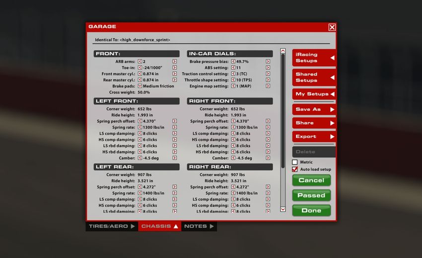
Table of Contents
CLICK TO VIEW A SECTION

 GENERAL INFORMATION

 A Message From iRacing »3

 Tech Specs »4

 Introduction »5

        Getting Started »5

        Loading An iRacing Setup »6

 Dash Pages »7

        Dash Configuration »7

        Pit Limiter »7

        Shift Lights »7

 ADVANCED SETUP OPTIONS

 Tires & Aero »9

        Tire Settings »9

        Aero Calculator »                                              10

 Chassis »12

        Front »12

        In-Car Dials »13

        Front Corners »14

        Rear Corners »16

        Rear »18

                             MCL AREN MP4-12C G T3   |   USER M ANUAL        2
DE AR iR ACING USER,
Congratulations on your purchase of the McLaren MP4-12C GT3! From all of us at iRacing, we appreciate
your support and your commitment to our product. We aim to deliver the ultimate sim racing experience,
and we hope that you’ll find plenty of excitement with us behind the wheel of your new car!
Based on the groundbreaking McLaren MP4-12C road car, the McLaren MP4-12C GT3 marries Formula
1 and innovative road-car technology to create a state-of-the-art racing sports car. The McLaren MP4-12C
GT3 utilizes the same carbon MonoCell chassis as the 12C road car, along its 3.8 liter McLaren V8 twin
turbo M838T engine, albeit detuned to 500 bhp in accordance with FIA regulations. The 12C GT3 features
a six speed Ricardo gearbox and an aero package developed in McLaren’s F1 simulator together with the
engine calibration, power steering, spring rates, weight distribution, gear ratios and differential settings.
The MP4-12C GT3 made its competition debut in the British GT Championship at Spa-Francorchamps
in July, 2012 and went on to score 19 victories across Europe in a variety of championships that same
season, including FIA GT1 World, Blancpain Endurance Series and Avon Tyres British GT as well as the
24 Hours of Barcelona. Subsequently the McLaren has become a staple of some of the sport’s most
successful GT teams in the Blancpain GT and Endurance Series as well as the Pirelli World Challenge.
The following guide explains how to get the most out of your new car, from how to adjust its settings off of
the track to what you’ll see inside of the cockpit while driving. We hope that you’ll find it useful in getting up
to speed.
Thanks again for your purchase, and we’ll see you on the track!

                                                                                                                     3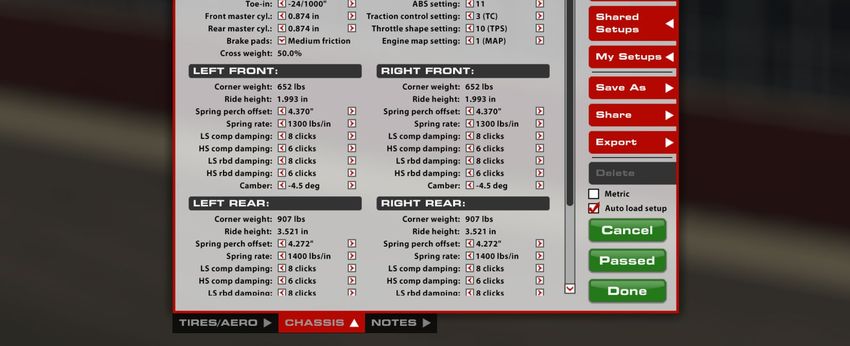
MCLAREN MP4-12C GT3   |   TECH SPECS

CHASSIS
INDEPENDEN T DOUBLE W ISHBONE
SUSPENSION FRON T AND RE AR

                                                                                                   WET WEIGHT
                            LENGTH        WIDTH              WHEELBASE      DRY WEIGHT             WITH DRIVER
                           4515mm      1995mm             2681mm            1278kg                 1414kg
                            177.8in      78.5in               105.6in           2818lbs             3117lbs

POWER
UNIT
TURBOCHARGED
90° V8

                                             DISPLACEMENT           RPM LIMIT             TORQUE              POWER

                                             3.8Liters           7820RPM             450lb-ft             500bhp
                                                  231.5CID                                610Nm               373kW

                           MCL AREN MP4-12C G T3      |   USER M ANUAL                                                4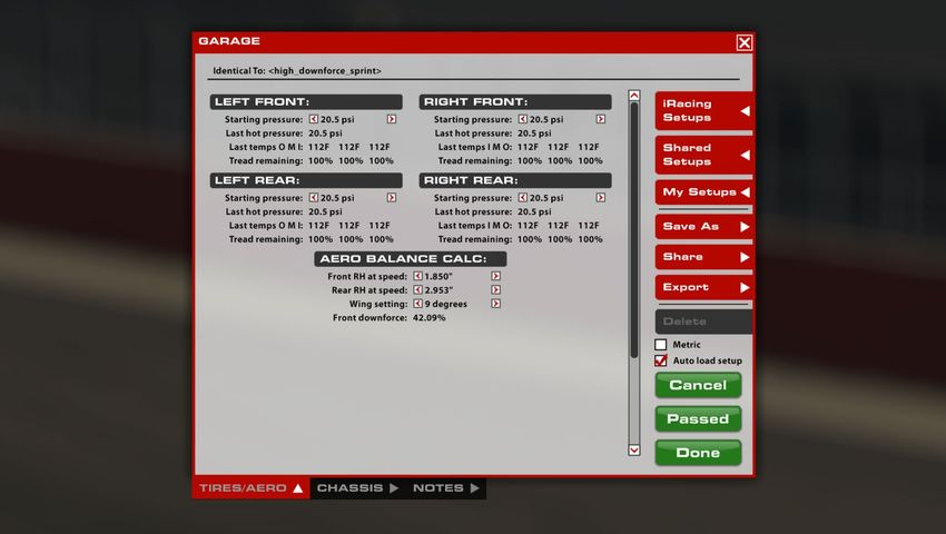
MCLAREN MP4-12C GT3                 |   INTRODUCTION

Introduction
The information found in this guide is intended to provide a deeper understanding of the
chassis setup adjustments available in the garage, so that you may use the garage to tune
the chassis setup to your preference.

Before diving into chassis adjustments, though, it is best to become familiar with the car
and track. To that end, we have provided baseline setups for each track commonly raced
by these cars. To access the baseline setups, simply open the Garage, click iRacing Setups,
and select the appropriate setup for your track of choice. If you are driving a track for which
a dedicated baseline setup is not included, you may select a setup for a similar track to use
as your baseline. After you have selected an appropriate setup, get on track and focus on
making smooth and consistent laps, identifying the proper racing line and experiencing tire
wear and handling trends over a number of laps.

Once you are confident that you are nearing your driving potential with the included baseline
setups, read on to begin tuning the car to your handling preferences.

GETTING STARTED

Before starting the car, it is recommended to map controls for Brake Bias, Traction Control and ABS adjustments. While this is
not mandatory to drive the car, this will allow you to make quick changes to the driver aid systems to suit your driving style while
out on the track.
Once you load into the car, getting started is as easy as selecting the “upshift” button to put it into gear, and hitting the accelerator
pedal. This car uses a sequential transmission and does not require a clutch input to shift in either direction. However the car’s
downshift protection will not allow you to downshift if it feels you are traveling too fast for the gear selected and would incur engine
damage. If that is the case, the gear change command will simply be ignored.
Upshifting is recommended when the shift lights on the dashboard are fully illuminated (but not flashing!). This is at 7000rpm.

                                          MCL AREN MP4-12C G T3           |   USER M ANUAL                                                  5
MCLAREN MP4-12C GT3 | INTRODUCTION
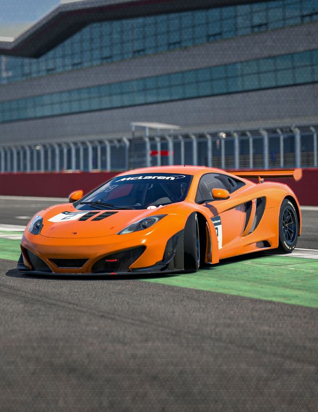
LOADING AN iRACING SETUP
Upon loading into a session, the car will automatically load the iRacing Baseline setup [baseline.sto]. If you would prefer one of
iRacing’s pre-built setups that suit various conditions, you may load it by clicking Garage > iRacing Setups > and then selecting the
setup to suit your needs.
If you would like to customize the setup, simply make the changes in the garage that you would like to update and click apply. If you
would like to save your setup for future use click “Save As” on the right to name and save the changes.
To access all of your personally saved setups, click “My Setups” on the right side of the garage.
If you would like to share a setup with another driver or everyone in a session, you can select “Share” on the right side of the
garage to do so.
If a driver is trying to share a setup with you, you will find it under “Shared Setups” on the right side of the garage as well.
MCL AREN MP4-12C G T3 | USER M ANUAL 6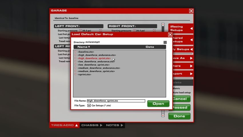
MCLAREN MP4-12C GT3      |   DASH PAGES

Dash Pages
The dash display in this car is non-adjustable and features a single page to
display critical vehicle information.
DASH CONFIGURATION

LEF T SIDE
WATER T		       Engine water temperatures (°C or °F)
OIL T			        Engine oil temperature (°C or °F)
OIL P			        Current engine oil pressure (Bar or psi)
FUEL P			       Current fuel pressure (Bar or psi)
FUEL U			       Fuel used this stint (relative to a full tank) (Litres or US Gallons)

CEN T ER
NUMBER/LETTER   Currently selected gear
OIL T			        Engine oil temperature (°C or °F)

RIGH T SIDE
V BATT			       Current battery voltage
MAP			          Current engine map setting
TIMER			        Current lap time
SYS P			        Gearbox hydraulic pressure (Bar or psi)

                               MCL AREN MP4-12C G T3            |   USER M ANUAL        7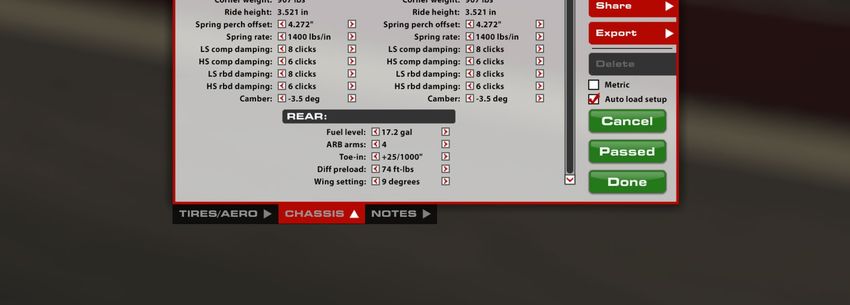
MCLAREN MP4-12C GT3               |   DASH PAGES

PIT LIMITER

When the pit limiter is active a message in red will appear at the top of the dashboard screen along with two cyan dots and two
orange arrows.

SHIFT LIGHTS

2 GREEN          6200 rpm
4 GREEN          6300 rpm
6 GREEN          6400 rpm
8 GREEN          6500 rpm
2 RED		          6600 rpm
ALL RED          6800 rpm

                                        MCL AREN MP4-12C G T3         |   USER M ANUAL                                            8
MCLAREN MP4-12C GT3                |   ADVANCED SETUP OPTIONS | TIRES & AERO

                                ADVANCED SETUP OPTIONS
              This section is aimed toward more advanced users who want to dive deeper into the different aspects
              of the vehicle’s setup. Making adjustments to the following parameters is not required and can lead to
              significant changes in the way a vehicle handles. It is recommended that any adjustments are made in
                      an incremental fashion and only singular variables are adjusted before testing changes.

Tires & Aero
TIRE SETTINGS (ALL FOUR)

C OLD AIR PRES SURE
Air pressure in the tire when the car is loaded into the world. Higher pressures will reduce rolling drag and heat buildup, but will
decrease grip. Lower pressures will increase rolling drag and heat buildup, but will increase grip. Higher speeds and loads require
higher pressures, while lower speeds and loads will see better performance from lower pressures. Cold pressures should be set
to track characteristics for optimum performance. Generally speaking, it is advisable to start at lower pressures and work your
way upwards as required.

                                         MCL AREN MP4-12C G T3          |   USER M ANUAL                                               9
MCLAREN MP4-12C GT3                |   ADVANCED SETUP OPTIONS | TIRES & AERO

HO T AIR PRES SURE
Air pressure in the tire after the car has returned to the pits. The difference between cold and hot pressures can be used to
identify how the car is progressing through a run in terms of balance, with heavier-loaded tires seeing a larger difference between
cold and hot pressures. Ideally, tires that are worked in a similar way should build pressure at the same rate to prevent a change
in handling balance over the life of the tire, so cold pressures should be adjusted to ensure that similar tires are at similar
pressures once up to operating temperature. Hot pressures should be analysed once the tires have stabilised after a period of
laps. As the number of laps per run will vary depending upon track length a good starting point is approximately 50% of a full fuel
run.

T IRE T EMPER AT URES
Tire carcass temperatures, measured via Pyrometer, once the car has returned to the pits. Wheel Loads and the amount of work
a tire is doing on-track are reflected in the tire’s temperature, and these values can be used to analyze the car’s handling balance.
Center temperatures are useful for directly comparing the work done by each tire, while the Inner and Outer temperatures are
useful for analyzing the wheel alignment (predominantly camber) while on track. These values are measured in three zones across
the tread of the tire. Inside, Middle and Outer.

T RE AD REM AINING
The amount of tread remaining on the tire once the car has returned to the pits. Tire wear is very helpful in identifying any possible
issues with alignment, such as one side of the tire wearing excessively, and can be used in conjunction with tire temperatures to
analyze the car’s handling balance. These values are measured in the same zones as those of temperature.

AERO CALCULATOR

The Aero Calculator is a tool provided to aid in understanding the shift in aerodynamic
balance associated with adjustment of the rear wing setting and front and rear ride
heights. It is important to note that the values for front and rear ride height displayed here
DO NOT result in any mechanical changes to the car itself, however, changes to the rear
wing angle here WILL be applied to the car. This calculator is a reference tool ONLY.

FRON T RH AT SPEED
The Ride Height (RH) at Speed is used to give the Aero Calculator heights to reference for aerodynamic calculations. When using
the aero calculator, determine the car’s Front Ride height via telemetry at any point on track and input that value into the “Front
RH at Speed” setting. It is advisable to use an average value of the LF and RF ride heights as this will provide a more accurate
representation of the current aero platform rather than using a single corner height.

                                         MCL AREN MP4-12C G T3          |   USER M ANUAL                                                 10
MCLAREN MP4-12C GT3 | ADVANCED SETUP OPTIONS | TIRES & AERO
RE AR RH AT SPEED
The Ride Height (RH) at Speed is used to give the Aero Calculator heights to reference for aerodynamic calculations. When using
the aero calculator, determine the car’s Rear Ride height via telemetry at any point on track and input that value into the “Front
RH at Speed” setting. It is advisable to use an average value of the LR and RR ride heights as this will provide a more accurate
representation of the current aero platform rather than using a single corner height.
W ING SE T T ING
The wing setting refers to the relative angle of attack of the rear wing, this is a powerful aerodynamic device which has a
significant impact upon the total downforce (and drag!) produced by the car as well as shifting the aerodynamic balance of the car
rearwards with increasing angle. Increasing the rear wing angle results in more total cornering grip capability in medium to high
speed corners but will also result in a reduction of straight line speed. Rear wing angle should be adjusted in conjunction with front
and rear ride heights, specifically the difference between front and rear ride heights known as ‘rake’. To retain the same overall
aerodynamic balance it is necessary to increase the rake of the car when increasing the rear wing angle.
FRON T DOW NFORCE
This value displays the proportion of downforce acting at the front axle for the given wing and ride height combination set within
the calculator parameters. This value is an instantaneous representation of your aero balance at this exact set of parameters and
it can be helpful to pick multiple points around a corner or section of track to understand how the aerodynamic balance is moving
in differing situations such as braking, steady state cornering and accelerating at corner exit. A higher forwards percentage will
result in more oversteer in mid to high speed corners.
MCL AREN MP4-12C G T3 | USER M ANUAL 11MCLAREN MP4-12C GT3 | ADVANCED SETUP OPTIONS | CHASSIS
Chassis
FRONT
ARB ARMS
The configuration of the Anti-Roll Bar arms, or “blades”, can be changed to alter the overall stiffness of the ARB assembly.
Increasing the number of ARB arms will increase the roll stiffness of the front suspension, resulting in less body roll but increasing
mechanical understeer. This can also, in some cases, lead to a more responsive steering feel from the driver. Conversely, reducing
the number of ARB arms will soften the suspension in roll, increasing body roll but decreasing mechanical understeer. This
can result in a less-responsive feel from the steering, but grip across the front axle will increase. Along with this, the effects of
softening or stiffening the ARB assembly in relation to aerodynamics should also be considered, softer ARB assemblies will result
in more body roll which will decrease control of the aero platform in high speed corners and potentially lead to a loss in aero
efficiency. 4 configurations of ARB arms are available and range from 1 (softest) to 4 (stiffest).
T OE -IN
Toe is the angle of the wheel, when viewed from above, relative to the centerline of the chassis. Toe-in is when the front of the
wheel is closer to the centerline than the rear of the wheel, and Toe-out is the opposite. On the front end, adding toe-out will
increase slip in the inside tire while adding toe-in will reduce the slip. This can be used to increase straight-line stability and turn-in
responsiveness with toe-out. Toe-in at the front will reduce turn-in responsiveness but will reduce temperature buildup in the front
tires.
MCL AREN MP4-12C G T3 | USER M ANUAL 12MCLAREN MP4-12C GT3 | ADVANCED SETUP OPTIONS | CHASSIS
FRON T M AS T ER CYLINDER
The Front Brake Master Cylinder size can be changed to alter the line pressure to the front brake calipers. A larger master
cylinder will reduce the line pressure to the front brakes, this will shift the brake bias rearwards and increase the pedal effort
required to lock the front wheels. A smaller master cylinder will do the opposite and increase brake line pressure to the front
brakes, shifting brake bias forward and reducing required pedal effort. 7 Different master cylinder options are available ranging
from 15.9 mm / 0.626” (highest line pressure) to 23.8 mm / 0.937” (lowest line pressure).
RE AR M AS T ER CYLINDER
The Rear Brake Master Cylinder size can be changed to alter the line pressure to the rear brake calipers. A larger master cylinder
will reduce the line pressure to the rear brakes, this will shift the brake bias forwards and increase the pedal effort required to
lock the rear wheels. A smaller master cylinder will do the opposite and increase brake line pressure to the rear brakes, shifting
brake bias rearward and reducing required pedal effort. 7 Different master cylinder options are available ranging from 15.9 mm /
0.626” (highest line pressure) to 23.8 mm / 0.937” (lowest line pressure).
BR AK E PADS
The vehicle’s braking performance can be altered via the Brake Pad Compound. The “Low” setting provides the least friction,
reducing the effectiveness of the brakes, while “Medium” and “High” provide more friction and increase the effectiveness of the
brakes while increasing the risk of a brake lockup.
CROS S W EIGH T
The percentage of total vehicle weight in the garage acting across the right front and left rear corners. 50.0% is generally optimal
for non-oval tracks as this will produce symmetrical handling in both left and right hand corners providing all other chassis settings
are symmetrical. Higher than 50% cross weight will result in more understeer in left hand corners and increased oversteer in
right hand corners, cross weight can be adjusted by making changes to the spring perch offsets at each corner of the car.
IN-CAR DIALS
BR AK E PRES SURE BI AS
Brake Bias is the percentage of braking force that is being sent to the front brakes. Values above 50% result in greater pressure
in the front brake line relative to the rear brake line which will shift the brake balance forwards increasing the tendency to lock
up the front tyres but potentially increasing overall stability in braking zones. This should be tuned for both driver preference and
track conditions to get the optimum braking performance for a given situation. It is important to note that differing combinations
of master cylinder size will necessitate differing brake pressure bias values, this is because increasing or reducing the split in
master cylinder size difference between front and rear axles will produce an inherent forward or rearward bias in brake line
pressure.
T R AC T ION C ON T ROL SW I T CH
This option determines if traction control is enabled, allowing you to completely disable the system if desired.
MCL AREN MP4-12C G T3 | USER M ANUAL 13MCLAREN MP4-12C GT3 | ADVANCED SETUP OPTIONS | CHASSIS
T R AC T ION C ON T ROL SE T T ING
The position of the traction control switch determines how aggressively the ecu cuts engine torque in reaction to rear wheel
spin. 3 positions are available. Settings 1-3 range from least intervention/sensitivity (position 3) through to highest intervention/
sensitivity (position 1). Position 2 is the recommended baseline setting. More intervention will result in less wheelspin and less
rear tire wear but can reduce overall performance if the traction control is cutting engine torque too aggressively and stunting
corner exit acceleration.
A B S SE T T ING
The current ABS map the car is running. 12 positions are available. Position 1 has the least intervention/support while position
11 has the most support. Position 12 disables the ABS completely. Position 2 is the recommended baseline setting. More
intervention reduces the possibility of and the duration of lockups during braking but can result in longer braking distances if the
system is set overly aggressive for the amount of available grip.
FRONT CORNERS
C ORNER W EIGH T
The weight underneath each tire under static conditions in the garage. Correct weight arrangement around the car is crucial for
optimizing a car for a given track and conditions. Individual wheel weight adjustments and crossweight adjustments are made via
the spring perch offset adjustments at each corner.
FRON T RIDE HEIGH T
Distance from ground to a reference point on the chassis. Since these values are measured to a specific reference point on the
car, these values may not necessarily reflect the vehicle’s ground clearance, but instead provide a reliable value for the height of
the car off of the race track at static values. Adjusting Ride Heights is key for optimum performance, as they can directly influence
the vehicle’s aerodynamic performance as well as mechanical grip. Increasing front ride height will decrease front downforce
as well as decrease overall downforce, but will allow for more weight transfer across the front axle when cornering. Conversely,
reducing ride height will increase front and overall downforce, but reduce the weight transfer across the front axle. Minimum legal
front ride height is 50.0 mm.
MCL AREN MP4-12C G T3 | USER M ANUAL 14MCLAREN MP4-12C GT3 | ADVANCED SETUP OPTIONS | CHASSIS
SPRING PERCH OFF SE T
Used to adjust the ride height at this corner of the car by changing the installed position of the spring. Increasing the spring perch
offset will result in lowering this corner of the car while reducing the spring perch offset will raise this corner of the car. These
changes should be kept symmetrical across the axle (left to right) to ensure the same corner ride heights and no change in cross
weight. The spring perch offsets can also be used in diagonal pairs (LF to RR and RF to LR) to change the static cross weight in
the car.
SPRING SELEC T ED/SPRING R AT E
This setting determines the installed corner spring stiffness. Stiffer springs will result in a smaller variance in ride height between
high and low load cases and will produce superior aerodynamic performance through improved platform control however, they
will also result in increased tire load variation which will manifest as a loss in mechanical grip. Typically the drawbacks of stiffer
springs will become more pronounced on rougher tracks and softer springs in these situations will result in increased overall
performance. Corner spring changes will influence both roll and pitch control of the platform and ARB changes should be
considered when altering corner spring stiffnesses in order to retain the same front to rear roll stiffness and overall balance.
When reducing corner spring stiffness the ARB stiffness should be increased to retain the same roll stiffness as previously. 14
options for spring rate are available ranging from 158 N/mm (900 lbs/in) to 385 N/mm (2200 lbs/in) in 18 N/mm (100 lbs/
in) steps. Spring perch offsets must be adjusted to return the car to the prior static ride heights after any spring rate change.
L S C OMP DAMPING
Low speed compression affects how resistant the shock is to compresion (reduction in length) when the shock is moving at
relatively low speeds, usually in chassis movements as a result of driver input (steering, braking, & throttle) and cornering
forces. In this case 0 is minimum damping (least resistance to compression) while 10 is maximum damping (most resistance to
compression). Increasing the low speed compression damping will result in a faster transfer of weight to this corner of the car
during transient movements such as braking and direction change with increased damping usually providing an increase in turn-in
response but a reduction in overall grip in the context of front dampers.
HS C OMP DAMPING
High speed compression affects the shock’s behavior in high speed travel, usually attributed to curb strikes and bumps in the
track’s surface. Higher compression values will cause the suspension to be stiffer in these situations, while lower values will allow
the suspension to absorb these bumps better but may hurt the aerodynamic platform around the track. At smoother tracks more
high speed compression damping will typically increase performance while at rougher tracks or ones with aggressive kerbs less
high speed compression damping can result in an increase in mechanical grip at the expense of platform control. 10 is maximum
damping while 0 is minimum damping.
L S RBD DAMPING
Low speed rebound damping controls the stiffness of the shock while extending at lower speeds, typically during body movement
as a result of driver inputs. Higher rebound values will resist expansion of the shock, lower values will allow the shock to extend
faster. Higher rebound values can better control aerodynamic attitude but can result in the wheel being unloaded when the
suspension can’t expand enough to maintain proper contact with the track. When tuning for handling, higher front low speed
rebound can increase on-throttle mechanical understeer (but reduce nose lift) while lower values will maintain front end grip
longer, helping to reduce understeer, but will allow more splitter lift. Excessive front rebound can lead to unwanted oscillations due
to the wheel bouncing off of the track surface instead of staying in contact. 10 is maximum damping (most resistant to extension)
while 0 is minimum damping (least resistance to extension).
MCL AREN MP4-12C G T3 | USER M ANUAL 15MCLAREN MP4-12C GT3 | ADVANCED SETUP OPTIONS | CHASSIS
HS RBD DAMPING :
High-speed rebound adjusts the shock in extension over bumps and curb strikes. Higher values will reduce how quickly the shock
will expand, while lower values will allow the shock to extend more easily. Despite not having as much of an effect on handling
in result to driver inputs, High-speed rebound can produce similar results in terms of aerodynamic control and uncontrolled
oscillations if set improperly. 10 is maximum damping while 0 is minimum damping.
C AMBER
Camber is the vertical angle of the wheel relative to the center of the chassis. Negative camber is when the top of the wheel is
closer to the chassis centerline than the bottom of the wheel, positive camber is when the top of the tire is farther out than the
bottom. Due to suspension geometry and corner loads, negative camber is desired on all four wheels. Higher negative camber
values will increase the cornering force generated by the tire, but will reduce the amount of longitudinal grip the tire will have
under braking. Excessive camber values can produce very high cornering forces but will also significantly reduce tire life, so it is
important to find a balance between life and performance. Increasing front camber values will typically result in increased front
axle grip during mid to high speed cornering but will result in a loss of braking performance and necessitate a rearward shift in
brake bias to compensate.
REAR CORNERS
RE AR RIDE HEIGH T
Distance from ground to a reference point on the rear of the chassis. Increasing rear ride height will decrease rear downforce
as well as increase overall downforce and will allow for more weight transfer across the rear axle when cornering. Conversely,
reducing ride height will increase rear downforce percentage but reduce overall downforce while reducing the weight transfer
across the rear axle. Rear ride height is a critical tuning component for both mechanical and aerodynamic balance considerations
and static rear ride heights should be considered and matched to the chosen rear corner springs for optimal performance.
Minimum legal rear ride height is 50.0 mm while maximum legal rear ride height is 95.0 mm.
MCL AREN MP4-12C G T3 | USER M ANUAL 16MCLAREN MP4-12C GT3 | ADVANCED SETUP OPTIONS | CHASSIS
SPRING SELEC T ED/SPRING R AT E
Similar to at the front axle, stiffer springs will result in a smaller variance in ride height between high and low load cases and will
produce superior aerodynamic performance through improved platform control at the expense of mechanical grip. This can be
particularly prominent when exiting slow speed corners with aggressive throttle application. Stiffer springs will tend to react
poorly during these instances especially so on rough tracks which will result in significant traction loss. Spring stiffness should
be matched to the needs of the racetrack and set such that the handling balance is consistent between high and low speed
cornering. As an example case, a car which suffers from high speed understeer but low speed oversteer could benefit from an
increase in rear spring stiffness. This will allow for a lower static rear height which will reduce rear weight transfer during slow
speed cornering while maintaining or even increasing the rear ride height in high speed cornering to shift the aerodynamic balance
forwards and reduce understeer. 15 options for spring rate are available ranging from 158 N/mm (900 lbs/in) to 280 N/
mm (1600 lbs/in) in 9 N/mm (50 lbs/in) steps. Spring perch offsets must be adjusted to return the car to the prior static ride
heights after any spring rate change.
L S C OMP DAMPING
Low speed compression affects how resistant the shock is to compresion (reduction in length) when the shock is moving at
relatively low speeds, usually in chassis movements as a result of driver input (steering, braking, & throttle) and cornering
forces. In this case 0 is minimum damping (least resistance to compression) while 10 is maximum damping (most resistance to
compression). Increasing the low speed compression damping will result in a faster transfer of weight to this corner of the car
during transient movements such as braking and direction change with increased damping usually increasing the cars tendency to
understeer on throttle application.
HS C OMP DAMPING
High speed compression affects the shock’s behavior in high speed travel, usually attributed to curb strikes and bumps in the
track’s surface. Higher compression values will cause the suspension to be stiffer in these situations, while lower values will allow
the suspension to absorb these bumps better but may hurt the aerodynamic platform around the track. At smoother tracks more
high speed compression damping will typically increase performance while at rougher tracks or ones with aggressive kerbs less
high speed compression damping can result in an increase in mechanical grip at the expense of platform control. 10 is maximum
damping while 0 is minimum damping.
L S RBD DAMPING
Low speed rebound damping controls the stiffness of the shock while extending at lower speeds, typically during body movement
as a result of driver inputs. Higher rebound values will resist expansion of the shock, lower values will allow the shock to extend
faster. As at the front, high rebound stiffness will result in improved platform control for aerodynamic performance and overall
chassis response but it is important to avoid situations where the shock is too slow in rebounding as this can result in the tire
losing complete contact with the track surface. Provided this is avoided,, an increase in rebound stiffness can help to ‘slow down’
the change in pitch of the car as the brakes are applied, increasing braking stability and off-throttle mechanical understeer. 10 is
maximum damping (most resistant to extension) while 0 is minimum damping (least resistance to extension).
HS RBD DAMPING :
High-speed rebound adjusts the shock in extension over bumps and curb strikes. Higher values will reduce how quickly the shock
will expand, while lower values will allow the shock to extend more easily. Despite not having as much of an effect on handling
in result to driver inputs, High-speed rebound can produce similar results in terms of aerodynamic control and uncontrolled
oscillations if set improperly. 10 is maximum damping while 0 is minimum damping.
MCL AREN MP4-12C G T3 | USER M ANUAL 17MCLAREN MP4-12C GT3 | ADVANCED SETUP OPTIONS | CHASSIS
C AMBER
As at the front of the car it is desirable to run significant amounts of negative camber in order to increase the lateral grip
capability however, it is typical to run slightly reduced rear camber relative to the front. This is primarily for two reasons, firstly, the
rear tires are 25 mm (~1”) wider compared to the fronts and secondly the rear tires must also perform the duty of driving the
car forwards where benefits of camber to lateral grip become a tradeoff against reduced longitudinal (traction) performance.
T OE -IN
At the rear of the car it is typical to run toe-in. Increasing toe-in will result in improved straight line stability and a reduction in
response during direction changes. Large values of toe-in should be avoided if possible as this will increase rolling drag and reduce
straight line speeds.
REAR
FUEL LE V EL
The amount of fuel in the fuel tank. Tank capacity is 115 L (30.4 g). Adjustable in 1 L (0.26 g) increments.
ARB ARMS
The configuration of the Anti-Roll Bar arms, or “blades”, can be changed to alter the overall stiffness of the ARB assembly.
Increasing the ARB assembly stiffness will increase the roll stiffness of the rear suspension, resulting in less body roll but
increasing mechanical oversteer. This can also cause the car “take a set” more quickly at initial turn-in. Conversely, reducing the
ARB assembly stiffness will soften the suspension in roll, increasing body roll but decreasing mechanical oversteer. This can
result in a less-responsive feel from the rear especially in transient movements, but grip across the rear axle will increase. 4
configurations of ARB arms are available and range from 1 (softest) to 4 (stiffest).
DIFF PREL OAD
Diff preload is a static amount of locking force present within the differential and remains constant during both acceleration and
deceleration. Increasing diff preload will increase locking on both sides of the differential which will result in more understeer when
off throttle and more snap oversteer with aggressive throttle application. Increasing the diff preload will also smooth the transition
between on and off throttle behaviour as the differential locking force will never reach zero which can be helpful in reducing lift-off
oversteer and increasing driver confidence. Typically diff preload should be increased when there is noticeable loss in slow corner
exit drive and/or over-rotation during transition between the throttle and brake in low to mid speed corners.
MCL AREN MP4-12C G T3 | USER M ANUAL 18You can also read