Measurement and analysis of backlash on harmonic drive - IOPscience
←
→
Page content transcription
If your browser does not render page correctly, please read the page content below

IOP Conference Series: Materials Science and Engineering

PAPER • OPEN ACCESS

Measurement and analysis of backlash on harmonic drive
To cite this article: Bin Wang et al 2019 IOP Conf. Ser.: Mater. Sci. Eng. 542 012005

View the article online for updates and enhancements.

                               This content was downloaded from IP address 46.4.80.155 on 14/10/2020 at 00:40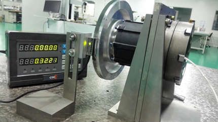
ICMEMSCE 2018                                                                              IOP Publishing
IOP Conf. Series: Materials Science and Engineering 542 (2019) 012005 doi:10.1088/1757-899X/542/1/012005

Measurement and analysis of backlash on harmonic drive

                     Bin Wang1, Jikui Liu2 and Chunjie Wang1

                     1 School of Mechanical Engineering and Automation, Beihang University, Beijing,
                     China
                     2 Beijing Institute of Control Engineering, Beijing, China
                     E-mail: binw502@126.com

                     Abstract. Harmonic drive transmissions are widely used in robotics, space manipulation
                     systems because of their excellent mechanical properties including low backlash, high speed
                     reduction ratio and compact size. Analytical investigation and modeling of backlash and
                     hysteresis for harmonic drive are reported, but no thorough understanding of backlash as well
                     as its attributes is available in literature. In this research, the experimental and analytical
                     studies of backlash are conducted. First, the definition of backlash according to China National
                     Standard (CNS) is given, which also matches the requirements in application. A dedicated
                     apparatus was designed to measure the backlash. The results of this paper offer an insight into
                     backlash of harmonic drive and the results are valuable in the mechanical design of harmonic
                     drive gears as well as the dynamic modeling and precision control of harmonic drive systems.

1. Introduction
Harmonic gear drive transmissions are compact, low-backlash, high-ratio, high-resolution rotary
motion transmissions. Military and civil mechanism benefit from these attributes[1]. In space
applications, high-stability SADA (Solar Array Drive Assembly) and high-precision antenna GDA
(Gimbal Drive Assembly) take advantage of the low-backlash characteristic of harmonic drive to
reduce the disturbance caused by vibration of large flexible components. The value of backlash in
harmonic drive transmission required is less than 3 arc minutes or even 1 arc minute.
The positional errors of harmonic drive transmission can be simply divided into two categories, the
kinematic error, which refers to pointing error when the input rotation is unidirectional, and backlash
error when reversing rotation is included. Emelyanov [2] carried out a mathematical analysis on the
kinematic error and concluded that the error was due to physical imperfections and assembly tolerance
of the three principle components in harmonic gear. The results in the report revealed that the
kinematic error periodically occurred twice per wave generator rotation. Besides, dynamic models of
harmonic drive transmission for various applications were built [3] [4][5], which all reduced the
maximum pointing error through implementing compensation.
Though the kinematic error in harmonic drive has been adequately studied, the literature known on
backlash error is relatively few, possibly due to the difficult access to sufficient experimental data
which will be explored later. Because of the complex source of backlash, we adopt experiment
measurement in this paper to investigate the characterization of backlash. When appropriate, the
seemingly random test data is explained analytically.

2. Measurement of backlash
Even though few experimental researches were obtained from known literature, the definition of
backlash is generally agreed According to CNS GB/T 12601-90, the backlash of harmonic drive which
              Content from this work may be used under the terms of the Creative Commons Attribution 3.0 licence. Any further distribution
              of this work must maintain attribution to the author(s) and the title of the work, journal citation and DOI.
Published under licence by IOP Publishing Ltd                          1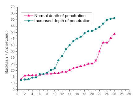
ICMEMSCE 2018                                                                              IOP Publishing
IOP Conf. Series: Materials Science and Engineering 542 (2019) 012005 doi:10.1088/1757-899X/542/1/012005

is also called lost motion is the angle lag of the output shaft when the input shaft change the rotational
direction in working condition. Hence the harmonic gear should be driven at input end with backlash
measured at the output end, as shown in Figure 1. Furthermore, the term “in working condition” in the
definition indicated that appropriate inertia or load of torque should be included at the output end. In
this section we present a precise characterization on the contribution of backlash and emphasize our
research on one particular aspect.

2.1. Mechanism of backlash
Through analysis of transmission principle, the backlash of harmonic drive transmission could be
decomposed into two dominant components including lost motion caused by clearance and lost motion
caused by elastic deformation. The source of clearance mainly includes tooth clearance between
circular spline and flexspline, the clearance from Oldham coupling in the wave generator, while the
elastic deformation is mainly due to flexspline under load of torque. The above process could be
shown in Figure 2 by analysing the transmission chain. The notation ΔФ is the summation of
clearance distributed among the transmission chain. Kt is the torsional stiffness, a variable which
increases with increasing load. The research in our experiment in the following sections focus on lost
motion caused by clearance.

     Figure 1. Backlash measurement apparatus     Figure 2. Harmonic drive transmission model
A method of calculation of tooth clearance for involute profile tooth in design state[6] is shown in
Figure 3. A coordinate system {0xyz} is fixed to the center of wave generator with y coaxial with
major axis, and {0x1y1z1} is fixed to a meshing flexspline tooth with y1 coaxial with its symmetric
line. Since the minimal clearance occurs at tooth top of the flexspline (point K1), it is chosen to
calculate the clearance. The coordinates of point K1 and K2 could be defined by the following
expression:

                           Figure 3. Theoretic clearance calculation diagram
The theoretic clearance in design state can thus be given by:
                              j ≈     (     −      ) +(       −      )                                (1)

                                                     2
ICMEMSCE 2018 IOP Publishing
IOP Conf. Series: Materials Science and Engineering 542 (2019) 012005 doi:10.1088/1757-899X/542/1/012005
The center angel or backlash can be expressed as:
∆= (2)
2.2. Measurement apparatus and procedure
The harmonic drive studied in our research is a cup type of 80 size, as shown in Figure 4, and its
parameters are listed in table 1. Figure 5 and 6 are photos of the backlash measuring apparatus as well
as its profile. In order to minimize the effect of uncertain factors, all testing samples were carefully
prepared in assembling except for intended purpose.
Figure 4. Three main components of harmonic gear
Table 1. Parameter of harmonic drive
Item Value Unit
Ratio 160:1
Design backlash 1 arc minute
Flexspline dimension 80 mm
Modulus 0.25 mm
Figure 5. View of measurement apparatus Figure 6. Profile of backlash
measurement apparatus
3. Characteristic of backlash
3.1. General characteristics
The test and analysis of harmonic drive backlash is a hard task due to the phenomenon that units from
the same batches may show completely different error signatures and even the same unit shows
different backlash in different assembly. What makes it worse is that the test method restricts the
number of test data, which makes it difficult to analyze its discipline. However, it is generally agreed
that, the backlash is involved with the following sources:
machining error of gear tooth of flexspline and circular spline;
machining error of cam profile;
3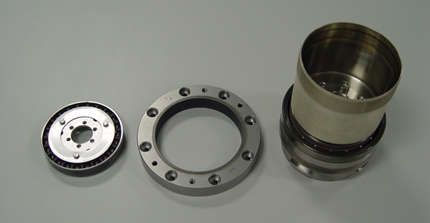
ICMEMSCE 2018 IOP Publishing
IOP Conf. Series: Materials Science and Engineering 542 (2019) 012005 doi:10.1088/1757-899X/542/1/012005
assemble error of the three components;
clearance of coupling;
and flexibility of flexspline and other parts.
Because the harmonic drive is rigidly connected to the input and output shaft and the test is carried out
in quasi-static without load of torque, the effects of the last two terms can be removed. In fact, their
influences are either relatively clear or sufficiently studied. In the subsequent sections, the machining
error and assembly tolerance which have important influences on backlash are experimentally tested
using the apparatus described above, and the results are analysed to give a physical explanation.
3.2. Assembly dependence
Another important reason for low backlash characteristic of harmonic drive besides multi-teeth
engagement is the existing angle between flexspline and circular spline along rotation axis, as shown
in Figure 7. The angle causes higher depth of meshing at outer area of the spline, which results in
smaller backlash of harmonic gear with no or little load. When the load of torque increases, the cup
flexes to allow more width of flexspline to engage with the circular spline, and the stiffness increases,
which explained the variable torsional stiffness discussed in section mechanism of backlash.
Figure 7. Harmonic drive cross section
Increasing the dimension of the major axis of wave generator could increase the meshing depth of
tooth and consequently decrease the backlash or increase the torsional stiffness of harmonic drive.
Johnson and Head [7] increased the torsional stiffness of harmonic drive by using wave generator of
different major diameter.
Increase in insert depth of wave generator into flexspline could similarly achieve the same objective.
Harmonic drive with wave generator inserted at different axial position were tested, one of the results
were shown in Figure 8. The values on the two curves were tested at the same 26 points uniformly
distributed on an output revolution. To enable a visual comparison and minimize the disturbance of
irregularity, the results were sorted in ascending order. As shown in figure, with 3 more millimeters
into the flexspline along axis, the backlash is obviously reduced, especially at positions of large
backlash.
3.3. Life dependence
The backlash requirement is to be satisfied throughout the life, and in systems with backlash
compensation, the value should remain stable during the whole life.
The wear contains two opposite aspects on backlash: 1) wear of tooth crest and tooth surface could
lead to increases of clearance; 2) accumulations of debris in wave generator and tooth slot decrease the
backlash. Both the phenomenon has been found in the life test of five units. The accumulations of
4ICMEMSCE 2018 IOP Publishing
IOP Conf. Series: Materials Science and Engineering 542 (2019) 012005 doi:10.1088/1757-899X/542/1/012005
debris especially metal debris caused zero backlash or even minus value backlash, and abnormal wear
were found in subsequent test after disassembly. For the units which passed the life test of about 4
million revolutions at the input end, variation of backlash is shown in Figure 9.
Figure 8. Dependence of backlash Figure 9. Dependence of backlash on life
on penetration depth of wave generator
4. Conclusions
In this paper new experimental measurement results and analysis were presented which give
new insight into the behavior of backlash in harmonic drives. A dedicated backlash
measurement apparatus as well as a test procedure were proposed which conformed to
application requirements. Extensive measurements were carried out using the apparatus.
Besides, we characterized the dependence of the backlash on assembly and life, revealing the
mechanism of backlash under different conditions. The measurement results obtained in this
paper are very useful in mechanical design of harmonic drive gear and precision dynamical
control systems involving backlash compensation.
5. References
[1]. Ivanov M 1987 The Harmonic Drive. Beijing: Defense Industry Press.
[2]. Emelyanov A 1983 Calculation of the kinematic error of a harmonic gear transmission taking
into account the compliance of elements. Soviet Engineering Research 3(7): 7-10.
[3]. Preissner C, Royston TJ and Shu D 2012 A high-fidelity harmonic drive model. ASME Journal
of Dynamic Systems, Measurement, and Control 134(1): 011002 1-3.
[4]. Preissner C, Shu D and Royston TJ 2007 Experimental investigation and model development
for a harmonic drive transmission. Proc. of SPIE (California, USA, 28 August 2007). Vol. 6665
(6665-0P).
[5]. Tuttle TD 1992 Understanding and modeling the behavior of a harmonic drive gear
transmission. Report,
[6]. Shen YW and Ye QT 1985 Theory and d Schempf H 1990 Comparative Design, Modeling,
and Control Analysis of Robotic Transmissions. Woods Hole Oceanographic Institution MIT
Report, USA, August.
[7]. Johnson MR, Gehling R and Head R 2006 Life test failure of harmonic gears in a Two-axis
Gimbal for the Mars Reconnaissance Orbiter Spacecraft. Jet Propulsion Laboratory Report,
USA, May.
5You can also read