Design and Analysis of a Robot Hand Based on the Combination of Continuous Flexible Finger and Rigid Tendon Drive Fingers - IOPscience
←
→
Page content transcription
If your browser does not render page correctly, please read the page content below
Journal of Physics: Conference Series

PAPER • OPEN ACCESS

Design and Analysis of a Robot Hand Based on the Combination of
Continuous Flexible Finger and Rigid Tendon Drive Fingers
To cite this article: Bo Zhang 2021 J. Phys.: Conf. Ser. 1802 022013

View the article online for updates and enhancements.

                               This content was downloaded from IP address 46.4.80.155 on 14/04/2021 at 05:43
CDMMS 2020                                                                                                      IOP Publishing
Journal of Physics: Conference Series                         1802 (2021) 022013          doi:10.1088/1742-6596/1802/2/022013

Design and Analysis of a Robot Hand Based on the
Combination of Continuous Flexible Finger and Rigid Tendon
Drive Fingers

                     Bo Zhang
                     Beijing Geegly University, China

                     bozhang@bgu.edu.cn

                     Abstract. As the most important end-effector of the robot, the robot hand determines the
                     performance of the robot to a certain extent. Therefore, the robot hand often needs
                     high degree of flexibility and larg grasping force to complete complex and diverse tasks.
                     However, most of the existing robot hands are usually difficult to meet the above two
                     requirements. Aiming at this problem, a dexterous robot hand driven by tendon ropes
                     was designed in this paper. Its thumb is a continuum flexible finger with a nickel-
                     titanium alloy wire as the center rod, and the remaining four fingers are tendon-driven
                     rigid fingers. This design allows the thumb to adapt to objects of various shapes, so that
                     the entire robot hand is extremely flexible, and the rigid structure of the four fingers can
                     provide an enough grasping force for the robot hand. In this paper, the robot hand was
                     mechanically designed and simulated by simulation software to ensure the reliability of
                     the design. The workspaces of fingers werecalculated by Matlab through the established
                     DH coordinate system and kinematics model of the robot fingers. In this paper, a
                     physical model of the robot hand was made through 3D printing technology, and
                     thin-film pressure sensors are installed at the end of the fingers to measure the grasping
                     force in real time. Finally, various shapes of objects were selected for the grasping
                     operation, which verified the flexibility and enough grasping force of the robot hand.

                     Keywords: Robot hand, continuum robot, flexibility, gripping force.

1. Introduction
Robots are particularly important in the fourth industrial revolution dominated by intelligent
manufacturing. In particular, the continuous iteration of robotic robot hands enables robots to replace
human hands to a certain extent and are widely used in various fields. However, in some unstructured
environments, the tasks performed by robots are more complicated, and most of the existing robot hands
are difficult to play a better role, especially taking into account flexibility and grasping force.
   The existing robot hands are mainly divided into two categories, namely rigid robot hands and
flexible robot hands. The DLR-HIT Ⅱ [1] [2]robot hand jointly developed by Harbin Institute of
Technology and the German Aerospace Agency is a relatively classic rigid robot hand. The fingertip
torque of the robot hand is large and the operation accuracy is high. However, the robot hand also has
problems such as insufficient flexibility, complex control, and high cost. It is difficult to perform well
              Content from this work may be used under the terms of the Creative Commons Attribution 3.0 licence. Any further distribution
              of this work must maintain attribution to the author(s) and the title of the work, journal citation and DOI.
Published under licence by IOP Publishing Ltd                          1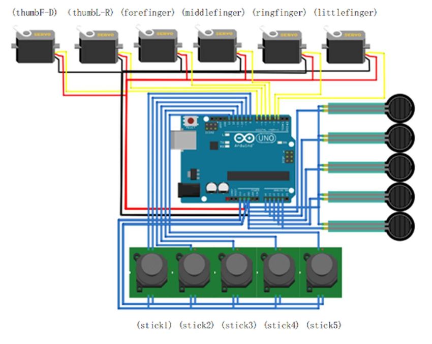
CDMMS 2020                                                                                 IOP Publishing
Journal of Physics: Conference Series          1802 (2021) 022013    doi:10.1088/1742-6596/1802/2/022013

when performing grasping tasks in a complex environment. In addition, rigid robot hands such as Gifu-
II and DLR-I [3] [4] also have this kind of common problems. Zhao and others from Cornell University
invented a flexible robotic hand that uses the flexible material and tendon drive, and this robotic hand
can estimate the size of the grasping force by the degree of bending of the optical fiber. This kind of
robot hand is relatively soft, can adapt to the shape of different objects, and has a certain degree of
flexibility. However, it also has some common problems of flexible robot hands such as small grasping
force and poor control accuracy.
    Aiming at some of the problems of the existing classic robot hands, this paper introduces a kind
of robot hand based on the combination of continuum flexible fingers [5] and tendon-driven rigid
fingers. The thumb of the robot hand adopts a continuum design, which has more degrees of freedom
than the traditional linkage design. This gives it the same flexibility as a human hand. The other four-
finger mechanism is designed with a tendon-driven linkage, which can provide an enough grasping force.
The cooperation of the two types of fingers can make the whole hand both flexible and with enough
grasping force, thereby ensure that the robot hand can complete more complex grasping tasks.
    1. The mechanical design of the robot hand includes flexible thumb joints and multi-link four fingers,
the angle and arc of the finger palm. And the simulation design of the control system. [6] [7]
    2. Establish the kinematics model of the five fingers. According to the established kinematics model
and static model, the manipulator is simulated and calculated under different gestures to solve the work
space. [8] [9]
    3. Create a solid model through 3D printing technology, conduct a simulation experiment of human
hand movements, and compare with the simulation results. [10]
    4. Draw conclusions.

2. Mechanical Design
The five fingers of a classic robot hand mostly use a connecting rod structure, and its degree of freedom
limits the workspace of the robot fingers and also affects the grasping flexibility of the hand. The degree
of flexibility of the human hand is mainly depends on the flexibility of the thumb, especially the root
of the thumb, which can rotate freely like a ball joint. This degree of freedom of rotation of the thumb
and the degree of freedom of bending of the other four fingers can be used to grasp objects of various
shapes. Therefore, if the thumb of the robot hand has the same degree of freedom, it can be as flexible
as a human hand. According to this research idea, we designed a robot hand based on the combination
of continuum flexible finger and rigid tendon-driven fingers, so that the five fingers of the entire robot
hand can have a degree of freedom similar to that of a human hand, thereby being more flexible.
    The overall structure of the robot hand in this paper is similar to the human hand, as shown in Figure
1. Among them, the index finger, middle finger, ring finger and little finger adopt the same structural
design. The three knuckles of each finger are rigid structures, and by stretching the tendon rope fixed at
one end to the fingertip, each knuckle can be rotated around the axis, So as to achieve the bending of
the entire finger. The thumb adopts a continuum structure supported by an elastic central skeleton and
multiple diskdisks arranged in parallel. The bending of the fingers is also driven by tendons. The thumb
structure of the robot hand is shown in Figure 1.

                                                     2
CDMMS 2020 IOP Publishing
Journal of Physics: Conference Series 1802 (2021) 022013 doi:10.1088/1742-6596/1802/2/022013
Figure 1. Robot hand and its parts
The thumb has a Nitinol wire with a diameter of 0.5mm as the central skeleton, which plays a role
of support and rebound. In the skeleton, a total of 15 small disks are inserted, each of which has a
thickness of 3mm and a diameter of 20mm. On each disk, there are eight holes with a diameter of 1.5mm
arranged in a circle, and the driving tendon is inserted into each disk through these holes. In order to
keep the center of each disk at a fixed distance, a joint ball is inserted between two adjacent disks so
that the disk does not move when the fingers are bent. Among them, in order to ensure that the fingers
can achieve a better bending effect, 7 joint balls with a diameter of 3mm are penetrated near the base of
the finger, and 7 joint balls with a diameter of 5mm are penetrated near the fingertip. The thumb of the
robot hand is driven by tendon ropes.Eight tendon ropes are inserted into the eight holes on the disk,
and every two adjacent tendon ropes are connected to one end of the steering wheel. When working, the
steering gear drives the ropes in different disk holes, which can cause the elastic skeleton to bend in the
corresponding direction, thereby controlling the movement of the thumb. The other four fingers of the
robot hand except the thumb are all connected rod structures, and the structure is shown on the left side
of Figure 1. The three knuckles of each finger are connected by pins. The back of the finger is inserted
with Nitinol wire as a rebound device, and the front part is inserted with a driving tendon rope to connect
the steering gear.
All the joints, palms and arms of the robot hand are printed with 3D printing material PLA. The final
assembly effect is shown in Figure 1 (middle)
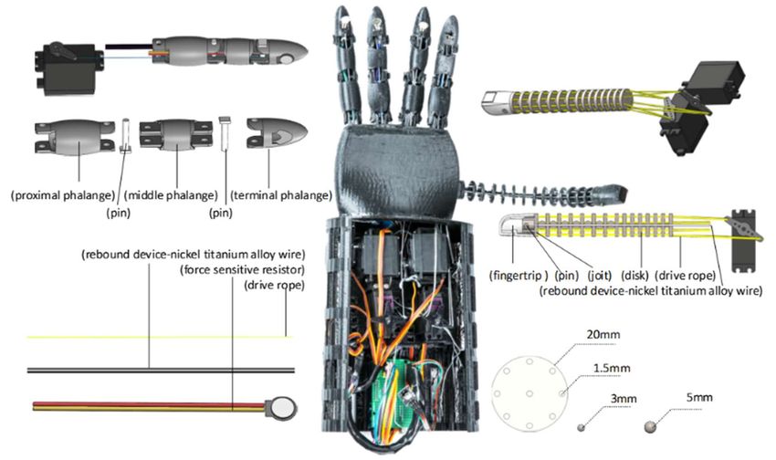
In this paper, a robot hand control system is made based on Aduino uno. The control circuit of the
robot hand is shown in Figure 2. The X port of joystick 1 controls the steering gear that moves the thumb
up and down; the Y port of joystick 1 controls the steering gear that moves the thumb left and right; the
joystick 2 controls the index finger steering gear; Stick 3 controls the middle finger servo; joystick 4
controls the ring finger servo; joystick 5 controls the little finger servo. When controlling the robot hand,
it sends a direction signal by manipulating the joystick. After receiving the signal, Aduino uno
recognizes the received signal through the program, controls the corresponding steering gear to rotate
and pulls the corresponding rope, so as to achieve the purpose of bending the fingers.
3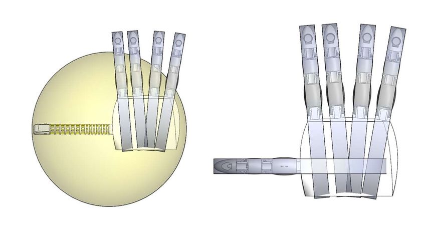
CDMMS 2020                                                                                  IOP Publishing
Journal of Physics: Conference Series           1802 (2021) 022013    doi:10.1088/1742-6596/1802/2/022013

                              Figure 2. The control circuit of the robot hand

    Pressure sensors are installed on the belly of each finger, which can measure the grasping force
generated when the finger grasps objects. When the finger touches the grasped object, the pressure
sensor on the fingertip returns the reaction force signal received to Aduino uno. When the reaction force
reaches the set limit value, Aduino uno will send a signal to prohibit the steering gear from continuing
to rotate in this direction.

3. Work Space
In order to analyze the finger motion state of the robot hand and the working area of the finger end, this
paper studies the workspace of the robot finger. By writing a program in MATLAB and performing
calculations, the workspace of the two fingers of the robot hand is obtained.
   For the four rigid connecting rod fingers, the parameters are shown in Table 1.

                           Table 1. The length of each joint of multi-link finger
                                                                            Relative range of motion
 Multi-link fingers     Finger root     Middle finger      Knuckles
                                                                                 between joints
                           43mm            38mm             35mm                       90°

                                                      4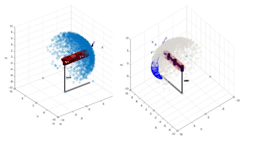
CDMMS 2020                                                                                     IOP Publishing
Journal of Physics: Conference Series             1802 (2021) 022013     doi:10.1088/1742-6596/1802/2/022013

                                          Figure 3. Multi-link fingers

   Through matlab calculation, it can be seen that the traditional multi-link fingers can only rotate in a
plane, and the three-dimensional working space is only a plane, as shown in Figure 3.
   In order to compare the difference between the working spaces of the two fingers, the same finger
length parameters are set in the model, and the working spaces of the two fingers are shown in Figure
4.

                                    Table 2. Flexible finger parameters

                                                                         Relative range of
                     Flexible           3mm       3mm         5mmjoi
                                                                         motion between
                   joint finger         disk      joint         nt
                                                                               joints

                                         15                     7               90°

                                                          5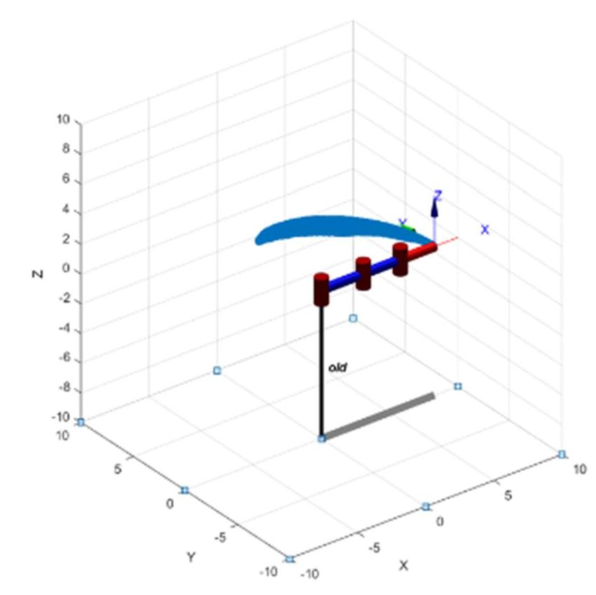
CDMMS 2020                                                                                 IOP Publishing
Journal of Physics: Conference Series           1802 (2021) 022013   doi:10.1088/1742-6596/1802/2/022013

                       Figure 4. Flexible finger (left) and comparison chart (right)

                      Figure 5. Comparison test diagram between model and hand

   After calculation, as shown in Figure 5 (left), the workspace of flexible finger is a three-dimensional
space, and it is much larger than that of multi-link fingers.
   Using the hold on function of the robot toolbox to retain images for comparison, as shown in the
comparison diagram of Figure 5(right), it is further confirmed that the workspace of flexible fingers is
much larger than multi-link fingers.

                                                     6
CDMMS 2020 IOP Publishing
Journal of Physics: Conference Series 1802 (2021) 022013 doi:10.1088/1742-6596/1802/2/022013
Figure 6. Workspace plan
Through the analysis module of the 3D software, the work space can be compared more intuitively.
It can be seen from Figure 6 that the design of the flexible finger thumb effectively improves the working
space of the robot hand.
4. Experiment
According to the analysis of the workspace of the robot fingers in the previous section, the workspace
of the robot hand with the flexible continuum structure of the joint thumb is analyzed and solved by the
simulation software. It is found that the workspace is greatly improved compared to the rigid link finger.
Various types of fingers can cooperate with each other to achieve tasks that cannot be completed by a
robot hand which only has rigid link fingers.
In order to further determine the feasibility of the grasping flexibility design of the robot hand
described in this article, in addition to software simulation, this article also carried out a grasping
experiment test with the simulated human hand posture by grasping objects of different shapes. By
controlling the robot hand to make a variety of enduring common complex and common operation
gesture simulations, the robot hand can achieve stable grasping of objects of different shapes. It is
verified that the feasibility experiment of the robot hand design in this paper is confirmed. The physical
test is shown in Figure 6, where eight kinds of gesture tests that are difficult to complete by conventional
multi-rigid link robot hands are entered.
As shown in Figure 6,
is an open gesture, showing the initial state of the five fingers.
(b) is the scissors hand gesture, showing the most common movements of the simulated human hand.
(c) is an ok gesture, showing that the thumb can be pinched with the index finger.
(d) In order to grasp the handshake, show that the five fingers can grasp the sphere.
(e) To hold the stick gesture, show that the fingers can hold the stick-like object.
(f) is a pinching gesture, showing the gripping force of the thumb and index finger. (g) To show the
driving force of the thumb by pressing the grace gesture.
(h) is to pinch objects to show the coordination of the five fingers.
Through a variety of human hand motion simulation experiments, the results show that the robot
hand with flexible continuum joint thumb has high flexibility, and its grasping performance is greatly
improved compared with the rigid link robot hand. The actual workspace and the software simulation
results are similar .
7CDMMS 2020 IOP Publishing
Journal of Physics: Conference Series 1802 (2021) 022013 doi:10.1088/1742-6596/1802/2/022013
5. Conclusion
In this paper, A novel robot hand with a flexible thumb and four rigid multi-link fingers was designed.
In order to ensuring the grasping space of these five fingers, the working space of these fingers are
analyzed. According to the work space of fingers, the flexible thumb is able to improve the ability to
grasp objects. Then, the physical model of this robot hand was made by using3D printing technology.
Finally, a experiment was carried out, and the experiment showes that this robot hand is able to achieve
different grasping gesture and garsps different kinds of objects.
References
[1] Butterfass, J. , et al. "Design and experiences with DLR hand II." Automation Congress, 2004.
Proceedings. World 2004.
[2] Liu, Hong , et al. "Multisensory five-finger dexterous hand: The DLR/HIT Hand II." Proc
IEEE/RSJ Int Conference on Intelligent Robots & Systems 2008.
[3] Kim, Hyung Il , et al. "Soft morphing hand driven by SMA tendon wire." Composites Part B
Engineering 105.nov. (2016): 138-148.
[4] Khondoker, Mohammad Abu Hasan , N. Baheri , and D. Sameoto . "Tendon-Driven Functionally
Gradient Soft Robotic Gripper 3D Printed with Intermixed Extrudate of Hard and Soft
Thermoplastics." 3D Printing and Additive Manufacturing 6.4(2019):191-203.
[5] Massa, B. , et al. "Design and development of an underactuated prosthetic hand." Proceedings of
the 2002 IEEE International Conference on Robotics and Automation, ICRA 2002, May 11-
15, 2002, Washington, DC, USA IEEE, 2002.
[6] Kim, Hyung Il , et al. "Soft morphing hand driven by SMA tendon wire." Composites Part B
Engineering 105.nov.(2016):138-148.
[7] Cho, Kyu Jin , and H. H. Asada . "Multi-Axis SMA Actuator Array for Driving Anthropomorphic
Robot Hand." IEEE International Conference on Robotics & Automation IEEE, 2005.
[8] Liu, Y. W., et al. "Embedded FPGA-based control of the HIT/DLR hand." IEEE/ASME
International Conference on Advanced Intelligent Mechatronics IEEE, 2005.
[9] Palli, G , et al. "Mechatronic design of innovative robot hands: Integration and control issues."
(2013).
[10] Faria, D. R., H. Aliakbarpour , and J. Dias . "Grasping Movements Recognition in 3D Space using
a Bayesian Approach." International Conference on Advanced Robotics IEEE, 2009.
8You can also read