Modeling the BP Oil Spill of 2010: A Simplified Model of Oil Diffusion in Water - BENG 221 - Fall 2012
←
→
Page content transcription
If your browser does not render page correctly, please read the page content below
Modeling the BP Oil Spill of 2010:
A Simplified Model of Oil Diffusion in Water
             BENG 221 – Fall 2012
                Eilleen Ao-Ieong
                  Anna Chang
                    Steven Gu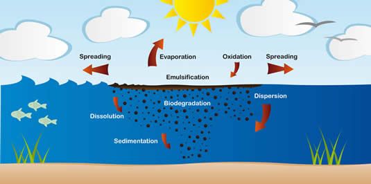
Introduction
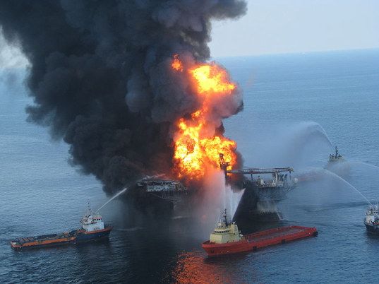
On April 20, 2010, the Deepwater Horizon mobile offshore drilling unit owned by British
Petroleum (BP) experienced a catastrophic explosion that caused it to collapse into the bottom
of the Gulf of Mexico (Figure 1). In the process, a sea-floor oil gusher that was connected to the
unit ruptured and started to spill oil into the Gulf. The spill lasted for about 5 months unabated
and was finally sealed off on September 19, 2010. However, by that time, the damage was
already done. The oil spill, known by many as the BP Oil Spill, had a huge impact on the Gulf of
Mexico and the environment. It polluted marine and wildlife habitats; it mutated several marine
life forms; it damaged the fishing and tourism industry; and it resulted in the loss of 4.9 million
barrels of crude oil. President Barack Obama described this incident as the “worst
environmental disaster America has ever faced.”
Figure 1: The explosion that triggered the BP Oil Spill. Image taken from Inhabitat.com
Problem Setup
Despite this tragic incidence, there is opportunity present for those in academia. The oil spill can
be modeled as the diffusion of oil in water, and the concentration of oil over time can be
determined based on the diffusivity of oil in water. However, in order to model the diffusion of oil
in water, it is important to remember that oil does not just diffuse in water. There are many
reactions and external forces at work that can alter the distribution and concentration of oil in
water, such as biodegradation, sedimentation, dissolution, dispersion, emulsification,
evaporation, and oxidation (Figure 2). In addition, the water currents in the Gulf of Mexico can
act as a driving force and cause the oil to spread out faster throughout the Gulf.
2Figure 2: The Fate of an Oil Spill. Image taken from ITOPF.com.
Therefore, to accurately measure the concentration of oil over time, it is important to take into
consideration all of the above reactions and forces into the model. However, these factors can
complicate the model, making it difficult to find a suitable solution.
To simplify the model so that an analytical and numerical solution can be achieved, the following
assumptions were made:
1. No boundary on oil spill, as size of ocean is much greater than scale of oil spill.
2. No biodegradation, sedimentation, dissolution, dispersion, emulsification, evaporation,
oxidation, and driving forces.
3. Constant oil source at a specific point in space.
4. Instant rise of oil to the surface of the Gulf, thereby making the z-axis irrelevant
These assumptions simplify the model such that the only force examined is the diffusion of oil in
water. Given these assumptions, the partial differential equation that describes the model is
simplified to the following:
∂u ⎛ ∂2 u ∂2 u ⎞
= D⎜ 2 + 2 ⎟
∂t ⎝ ∂x ∂y ⎠
The initial and boundary conditions, respectively, are as follows:
u(x, y,t = 0) = δ (x)δ (y)
⎧u(x = ∞, y,t) = 0
⎨
⎩u(x, y = ∞,t) = 0
where the δ (x) and δ (y) functions imply infinite concentration at the point source, meaning
that at (x, y) = (0,0) , the concentration of oil is at infinity (i.e., no dilution with water), while at
(x, y) ≠ (0,0) , the concentration of oil is zero.
3Two methods were used to solve this model. For the analytical solution, the Green’s function for
infinite domain was used; for the numerical solution, the pdepe function from MATLAB was used.
Analytical Solution
To solve the model analytically, first solve for the Green’s Function. Start by finding the 1D
Green’s function solution and then extrapolate to 2D.
1. Write out 1D diffusion equation with IC and BC. The driving term is a delta function.
∂u
∂t
∂2 u
=D 2
∂x
{ u( ±∞,t )=0
u( x,t=0)=δ ( x )
m2
*D = 1.13× 10⁻³
day
*See Appendix for Derivation of Diffusion Coefficient, D
2. Perform Fourier Transform in the Spatial Domain since the x domain is infinite.
U (x,t) → U F (ω ,t)
∂uF
= − Dω 2U F
∂t
3. Perform Laplace Transform in the Time Domain since t is defined for all time t > 0 . The
Laplace transform of the delta function is 1.
U F (ω ,t) → U FL (ω ,s)
sU FL − U F (ω ,0) = − Dω 2U FL
U F (ω ,0) = L {δ } = 1
4. Solve the resulting equation for U FL algebraically
1
U FL =
s + Dω 2
5. Perform Inverse Transforms to get back u .
L−1 {U FL } = U F = e− Dω
2
− x2
1
F −1
{U } = u =
F
e 4 Dt
4π Dt
46. Extrapolate to 2D. With the addition of the y coordinate, we would have an additional
Fourier Transform and inverse transform. This would change our Green’s function by an
1
additional factor of .
4π D(t − t0 )
−[( x−x0 )2 +( y−y0 )2 ]
1
G ( x,t, x0 ,t 0 ) = e 4 D(t−t 0 )
4π D(t − t 0 )
The general solution using the Green’s Function is as follows:
L L t
u(x,t) = ∫ g(x0 )G(x,t; x0 ,0)dx0 + ∫ ∫ Q(x0 ,t 0 )G(x,t; x0 ,t 0 )dx0 dt 0
0 0 0
∂
t t
+ ∫ u0 (t 0 )D G(x,t;0,t 0 )dt 0 − ∫ u L (t 0 )G(x,t; L,t 0 )dt 0
0
∂x0 0
Since the model does not have a driving force, and the concentration of oil at the boundaries is
zero, the solution simplifies to just the following:
t ∞ ∞
u(x,t) = ∫ ∫ ∫ G ( x,t, x ,t )δ (x )δ (y )dx
0 −∞ −∞
0 0 0 0 0 dy0 dt 0
t ∞ ∞ −[( x−x0 )2 +( y−y0 )2 ]
1
=∫∫ ∫ e 4 D(t−t 0 )
dx0 dy0 dt 0
0 −∞ −∞
4π D(t − t 0 )
t −( x 2 +y 2 )
1
=∫ e 4 D(t−t0 ) dt 0
0
4 π D(t − t 0 )
The integral above cannot be computed directly, so the answer was approximated using the
Midpoint Approximation Method. Using this method, the concentration of oil can be plotted over
an interval of 150 days (or about 5 months, the duration of the BP oil spill).
5Figure 3: Concentration of Oil at Day 30
Figure 4: Concentration of Oil at Day 60
6Figure 5: Concentration of Oil at Day 90
Figure 6: Concentration of Oil at Day 120
7Figure 7: Concentration of Oil at Day 150
It is important to note that the initial condition is set to an infinite concentration that
transcends the bounds of the y-axis in the graphs. This initial condition is such that the
concentration of oil is infinity when (x, y) = (0,0) and zero when (x, y) ≠ (0,0) . Because this
initial condition takes place at only one point in the x-y domain, it results in an extremely thin
vertical line that is impossible to distinguish at the current resolution. It is important to take
this ‘invisible’ vertical line into account when analyzing the graphs. Figures 3 to 7 show the
progression of the diffusion of oil through time and space. As time goes by, oil slowly
spreads radially. The concentration profile maintains a Gaussian distribution, suggesting
that most oil remains at the site of the spill. As the oil diffuses, the concentration decreases.
Figure 7 shows that this Gaussian distribution is wider at the bottom after 150 days.
However, there is no change at the origin, suggesting that oil is still mainly concentrated at
the source. After 150 days, the spread is only diffused within a 2m2 radius.
Based on the magnitude of the damage and the controversy arising from the BP oil spill, the
results of the analytical solution seem surprising. However, this problem was solved under
various assumptions that make the spread of oil only dependent on diffusion. The small
magnitude of the diffusion coefficient suggests that diffusivity plays a minimal role on the
dispersion of oil, and in order to realistically simulate an oil spill, other forces must be taken
into account.
Numerical Solution
A similar solution can be obtained, using MATLAB’s pdepe function (see appendix for code). For
the numerical solution, a one-dimensional approach was used to simplify the problem, as it is
symmetrical from the source of the oil spill to all direction in the plane. Based on the analytical
solution we limited the x-axis to 5 meters, as further simulation would not make a difference.
The initial conditions of this model consisted of a delta function in the x domain, meaning the
concentration of oil will be infinite at the origin and zero elsewhere at time t = 0 . To simulate
this initial condition in our pdepe function, a relatively large value (600) was used as our initial
condition. However, because this is a one-dimensional solution, a left value boundary condition
8was applied at the initial concentration of the spill to simulate the delta function. Assuming
infinite concentration at the origin of the spill, it can be generalized that a high concentration of
oil at that boundary will be constantly maintained throughout time.
Figure 8: One-Dimensional Oil Spill, Using MATLAB’s pdepe Function
The numerical solution depicted by Figure 8, shows a similar trend seen in the analytical
solution. At t = 0 and x = 0 , the oil spill is at a maximum concentration. As time progresses, the
concentration spreads out towards the x direction. Based on Figure 8, it can be observed that
diffusion is extremely slow, because after 150 days, the majority of the oil still remains at the
origin, with some oil diffusing within a 2m2 area. This is also depicted by the concentration
profile at different time points as observed in Figure 9.
Figure 9: Concentration Profile at Different Times
9Discrepancies between the Analytical and Numerical Solution
The main discrepancies between these two methods should arise from the simulation of the
initial condition. In the analytical solution, the initial condition is set such that the source at the
origin has an infinite concentration. However, for the numerical solution, a relatively large
number (600) was utilized to emulate an infinitely high concentration and used as a left value
boundary condition. Furthermore, instead of an infinite boundary, the numerical solution was
simulated to have a boundary at x=5, as simulation beyond that point would make no difference.
Judging from the graphical solutions obtained by both methods, the discrepancies resulting from
this adaptation on the initial conditions do not affect the solutions. Both methods exhibit a similar
trend: the maintenance of high concentration at the origin and the slow diffusion of oil after 150
days. Both solutions show that after 150 days, the oil is still constrained within a 2m2 region,
following a Gaussian distribution from the origin of the spill.
Conclusion and Future Works
Both the analytical and numerical solutions show that the diffusion of oil follows a Gaussian
trend, with the oil remaining primarily at the source of the spill and spreading within a 2m2 area
after 150 days. However, this simplified model contradicts the real magnitude of the BP Oil Spill,
demonstrating that diffusion alone is not enough to promote the spreading of oil in water. Other
forces and reactions need to be taken into account to obtain a real-life model of the oil spill.
Future directions should include a term that corresponds to the Gulf’s water current, a term that
corresponds to the reactions that occur between oil and water such as biodegradation,
emulsification, and sedimentation, and a sink term that would correspond to the cleanup of oil.
The inclusion of these factors would produce a much more realistic model of an oil spill, which
can be helpful in predicting the magnitude of an oil spill and facilitating an adequate plan of
action.
10Appendix
Derivation of Diffusion Coefficient of Oil in Water
In Hamam’s 1987 paper, The Diffusion on Oil in Water, the diffusion coefficient of oil in water D,
in units of cm2 per hour, was provided as a function of temperature T in Celsius:
D = 4.13 × 10 −3 T 1.53 . According to data present on the US National Oceanographic Data Center
website, the average water temperature of the Gulf of Mexico was calculated to be 22℃. Using
cm 2
this value, the diffusion coefficient of oil in water was calculated to be D = 0.47 . The
hr
diffusion coefficient was then converted to units of m2 per day, resulting in the final value of
m2
−3
D = 1.13 × 10 .
day
Code for Finding and Plotting Analytical Solution
%select the time at which to see solution
t=5*30;
%initiate
D=(0.5*10^-4)*24; %[m^2/day]
L=5; %how far are we looking in [m]
dx=.1;
xmesh= -L:dx:L;
nx= length(xmesh);
dy=.1;
ymesh= -L:dx:L;
ny= length(ymesh);
unum=zeros(nx,ny);
%set up integration
a=0;
b=t;
n=150; %number of steps
dh=5*t/n; %stepwidth
hmesh=0:dh:t; %vector of step locations
nh=length(hmesh);
w=2*dh;
%integrate and plot
for i=2:nh
for x=1:nx
for y=1:ny
unum(x,y)=unum(x,y)+...
w*exp(-(xmesh(x)^2+ymesh(y)^2)/...
(4*D*hmesh(i)))/(4*pi*D*hmesh(i));
end
end
figure(1);
filename = 'integrator.gif';
surf(xmesh,ymesh,unum,'LineStyle','none')
% Create xlabel
xlabel('x (m)','FontSize',14);
11xlim([-5 5]);
% Create ylabel
ylabel('y (m)','FontSize',14);
ylim([-5 5]);
zlabel('concentration','FontSize',14);
zlim([0 650]);
% Create title
title(['Concentration of Oil at Day ',num2str(hmesh(i))],'FontSize',14);
drawnow
frame = getframe(1);
im = frame2im(frame);
[imind,cm] = rgb2ind(im,256);
if i == 2;
imwrite(imind,cm,filename,'gif', 'Loopcount',inf);
else
imwrite(imind,cm,filename,'gif','WriteMode','append');
end
end
Code for MATLAB’s pdepe Plot and Concentration Profile
function project_numerical
clc;clear all;close all;
global D c0 L ;
D = 1.3e-3; %m^2/s;
c0= 600; %mmol/m^3
L=5; %m
t_max= 150;
t=linspace(0, t_max, 200);
x=linspace(0,L, 100);
theta=(linspace(0, 2*pi,200));
sol_pdepe = pdepe(0,@pdefun,@ic,@bc,x,t);
sol_pdepe_t=sol_pdepe';
figure(1)
surf(t,x,sol_pdepe_t, 'EdgeColor', 'none')
title('Oil Spill One Dimensional pdepe')
xlabel('Time [days]')
ylabel('Length x [m]')
zlabel('Concentration ')
figure(2)
h1=plot(x, sol_pdepe_t(:,1),'b');
hold on
%plot(x, sol_pdepe_t(:,50));
h2=plot(x, sol_pdepe_t(:,25), 'r');
%plot(x, sol_pdepe_t(:,100));
h3=plot(x, sol_pdepe_t(:,150), 'g');
12legend([h1, h2, h3],{'1 day','25 days', '150 days'});
title(['Concentration Profile at Different Times']);
xlabel('x[m]');
ylabel('Concentration');
end
% function definitions for pdepe:
% --------------------------------------------------------------
function [c, f, s] = pdefun(x, t, u, DuDx)
% PDE coefficients functions
global D
c = 1;
f = D * DuDx; % diffusion
s = 0; % homogeneous, no driving term
end
% --------------------------------------------------------------
function u0 = ic(x)
% Initial conditions function
u0=(x==0);
end
% --------------------------------------------------------------
function [pl, ql, pr, qr] = bc(xl, ul, xr, ur, t)
% Boundary conditions function
global c0
pl = ul-600; % c0 value left, chose a large number to simulate infinity
ql = 0; % arbitrary flux left boundary condition
pr = 0; % zero value right boundary condition
qr = 1; % no flux right boundary condition
end
13References
Cauwenberghs, G. (2012). Introduction: PDEs in Linear Space and Time. Retrieved from UC
San Diego, BENG 221 Mathematical Methods in Bioengineering Website:
http://www.isn.ucsd.edu/courses/beng221/
Hamam, S.E.M. (1987). Diffusion of Crude Oil. Journal of Environmental Science and Health,
105(2), 445-456. doi:10.1080/10934528709375362
Inhabitat. (2012). Bill Introduced in Congress Will End $113 Billion in Fossil Fuel Subsidies.
Retrieved November 8, 2012, from http://inhabitat.com/bill-introduced-in-congress-
would-end-113-billion-in-fossil-fuel-subsidies/
National Commission on the BP Deepwater Horizon Oil Spill and Offshore Drilling. (2011). Part
II - Explosion and Aftermath: The Causes and Consequences of Disaster, Chapter 6.
Washington, D.C.: Bob Graham, William K. Reilly, Frances G. Beinecke, Donald Boesch,
Terry D. Garcia, Cherry A. Murray, & Frances Ulmer. Retrieved from
http://www.oilspillcommission.gov/sites/default/files/documents/FinalReportChapter6.pdf
National Oceanographic Data Center. (2012). Coastal Water Temperature Table – Gulf of
Mexico Coast: Eastern. Retrieved November 8, 2012, from
http://www.nodc.noaa.gov/dsdt/cwtg/egof.html
Pauls Online Notes: Calculus II - Approximating Definite Integrals
(http://tutorial.math.lamar.edu/Classes/CalcII/ApproximatingDefIntegrals.aspx)
The International Tanker Owners Pollution Federation Limited. (2010). Behavior of Oil at Sea.
Retrieved November 8, 2012, from http://www.itopf.com/marine-spills/fate/weathering-
process/
14You can also read