Experimental research of equipment for burying in the ground the drip irrigation lines
←
→
Page content transcription
If your browser does not render page correctly, please read the page content below
E3S Web of Conferences 286, 03011 (2021) https://doi.org/10.1051/e3sconf/202128603011
TE-RE-RD 2021

 Experimental research of equipment for burying
 in the ground the drip irrigation lines
 Dragoș Manea1,*, Eugen Marin1, Gabriel Gheorghe1, Cătălin Persu1, and Roxana Mitroi2
 1
 National Institute of Research - Development for Machines and Installations designed to Agriculture
 and Food Industry - INMA, Bucharest 013813, Romania
 2
 University Politehnica of Bucharest, Faculty of Biotechnical Systems Engineering, 313 Splaiul
 Independenței, 060042, sector 6, Bucharest, Romania

 Abstract. The equipment for burying in the ground the drip irrigation
 lines was designed and built at INMA Bucharest, within a complex
 research project carried out in partnership with other institutes, universities
 and research stations in Romania. The equipment is intended for drip
 irrigation technology for field crops. Subsurface crop irrigation technology
 is a variant of the classic drip irrigation technology, in which the drip lines
 are buried below the soil surface, providing water directly to the root zone
 of the plants. The depth of burial and the distance between the drip lines
 depends on the type of soil and the structure of the roots of the crop. The
 activities prior to the experimental research consisted in determining the
 characteristics of the test field (soil compactness, soil moisture,
 geographical coordinates of location). Experimental research of the
 equipment aimed at determining the energy indices (working speed,
 traction force, traction power, working capacity and fuel consumption).

 1 Introduction
 Subsurface crop irrigation technology is a variant of classical drip irrigation technology, in
 which drip lines are buried below the soil surface, providing water and / or fertilizer
 directly to the plant root zone. Compared to surface drip irrigation, subsurface irrigation
 technology has the following advantages: it eliminates surface evaporation; reduces water
 stress of the crop; prevents weed germination and reduces the use of herbicides; reduces the
 need for labour; reduces maintenance costs and ensures the safe and efficient delivery of
 fertilizers.
 The equipment for burying pipes for subsurface drip irrigation is composed of a towed
 frame on which are mounted drums with tubes in the form of a coil which run through a
 section for burying in the soil at different depths.
 There are relatively little research in the literature on equipments for burying drip
 irrigation lines in the ground. It is known from the prior art document [1], where the gutter
 opening organs are simultaneously assisted by other organs, which, as the irrigation tube is
 unrolled, cover the ditch with the soil resulting from the excavation.
 Internationally, various equipments are being built for the placement of irrigation hoses
 in the ground, manufactured by prestigious companies [2, 3, 4]. Compared, these
 equipments differ from each other by the width and depth of work, the number and
 construction of the working organs, the power of the tractor with which they are intended to
 work in the aggregate, etc. Instead, the technology of subsurface drip irrigation has been
 studied over time by several researchers [5 - 8].

 *
 Corresponding author: manea_dragos_05@yahoo.com

© The Authors, published by EDP Sciences. This is an open access article distributed under the terms of the Creative Commons
Attribution License 4.0 (http://creativecommons.org/licenses/by/4.0/).
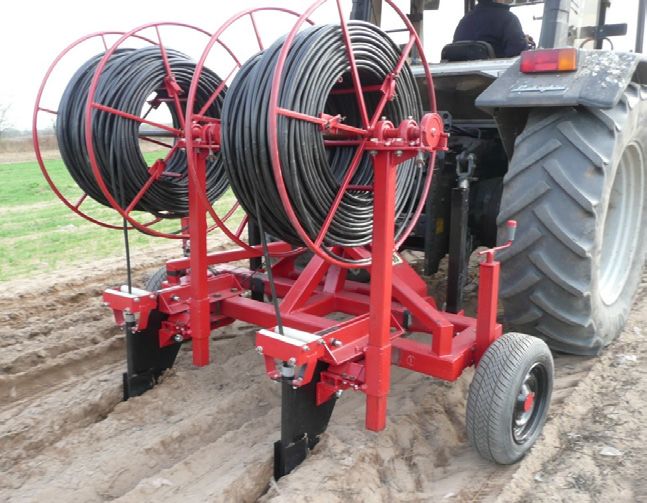
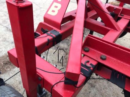
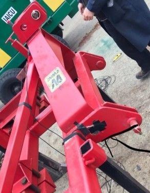
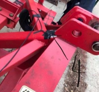
E3S Web of Conferences 286, 03011 (2021) https://doi.org/10.1051/e3sconf/202128603011
TE-RE-RD 2021

 Subsurface drip irrigation gives higher crop yield compared to surface drip irrigation
 [9], it can reduce the environmental risks and decrease nitrate leaching rates [10], but it has
 the disadvantage that it is very dificult to observe when a transmitter gets clogged [11].
 Within a complex project developed in partnership with other research institutes, public
 universities and research resorts in Romania, INMA Bucharest designed and built
 equipment for burying drip irrigation hoses in the ground (fig. 1), intended for agricultural
 farms who want to implement the technology of subsurface irrigation of hoeing plants or
 vegetable crops, in the open field. This equipment works in aggregate with wheeled
 agricultural tractors, provided with suspension mechanisms in three points category III
 according to ISO 730: 2012. The equipment is of the type carried on the hydraulic lift of the
 tractor, it has two working elements of vertical blade type and chisel knife, the distance
 between the organs being adjustable in the interval 70-140 cm and the working depth being
 between 15 and 45 cm.

 Fig. 1. The research object: equipment for burying drip irrigation lines in the ground

 This paper presents the results of experimental research on the equipment for burying
 drip irrigation lines in the ground, research that aimed to determine energy indices (working
 speed, traction force, traction power, working capacity, fuel consumption), in the conditions
 of an arid area in Romania and a sandy soil.
 2 Material and method
 The experiments of the technical equipment for burying drip irrigation lines in the ground
 were carried out within the Testing Department of INMA Bucharest and in the experimental
 plot of SCDCPN Dăbuleni, during October - November 2020. The experimental research was
 carried out in several stages.
 In the first stage, in the most critical points on the equipment were glued with special
 adhesives tensometric marks KYOWA model KFSG-6-120-C1-11N15C2, 120 Ω,
 temperature coefficient 11 ppm/°C, which measures the components force parallel to the
 direction of movement of the equipment and perpendicular to this direction (Fig. 2).

 Fig. 2. Tensometric marks glued to critical points on the equipment frame

 2
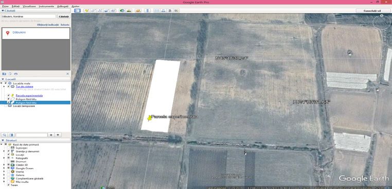
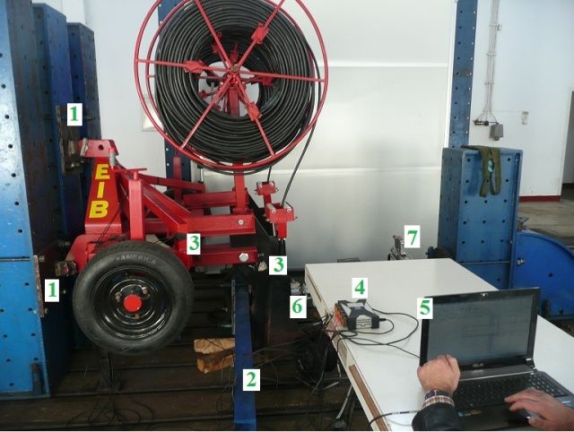
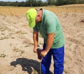
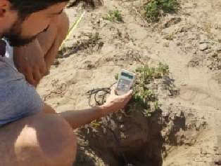
E3S Web of Conferences 286, 03011 (2021) https://doi.org/10.1051/e3sconf/202128603011
TE-RE-RD 2021

 The next step was to assemble the equipment on the experimental laboratory stand and
 calibrate the tensometric marks (Fig. 3). The equipment used consisted of: Hydropuls
 installation (hydraulic actuator; load cell 10 - 100 kN, Type FC-10, series 8608, with
 reading on the deck SERIES 366.90 / 87/13/1987, measurement uncertainty 0.89%), laptop
 with specialized software package; QuantumX 1615 data acquisition system, 2 modules
 with 32 measurement channels each module.

 Fig. 3. Experimental stand for calibration of tensometric marks in the laboratory: 1 - fixing elements
 on the stand of the equipment; 2 - drawbar; 3 - tensometric marks glued in the critical points; 4 - data
 acquisition system; 5 - laptop; 6 - hydraulic actuator; 7 - load cell

 The third step was to determine the characteristics of the test plot (Fig. 4). The soil of
 the experimental polygon of SCDCPN Dabuleni is a sandy soil, poorly developed
 (psamosol), with a coarse sandy texture (74-84% coarse sand), contains little clay (0.7-3%)
 and dust (2-4% ).

 location of the experimental polygon
 measuring soil soil moisture
 (geographical coordinates:N 43°48'30.24", E
 compactness measurement
 24°0.3'5.76")
 Fig. 4. Aspects during the determination of the characteristics of the test plot

 The FIELDSCOUT SC 900 digital cone penetrometer was used to measure the
 compactness of the soil. The measurements were performed at five points located on the
 diagonal of the experimental polygon. The average value of the resistance forces to the
 penetration of the cone in the soil layers in the depth range 0÷40 cm is 4694 kPa, which
 means that the soil falls in the middle class of compaction. Soil moisture was measured
 with the Delta - T Devices portable humid - meter, model HH2 with Theta Probe ML2x
 probe, at the same points where the compactness was measured and on the same depth
 range. The average value of soil moisture at a depth of about 20 cm was 6.5%, and at a
 depth of about 40 cm it was 16.8%.

 3
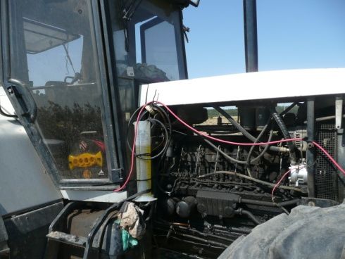
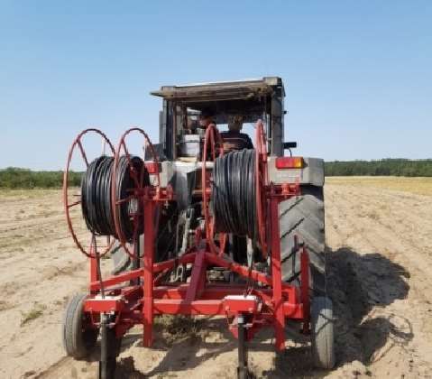
E3S Web of Conferences 286, 03011 (2021) https://doi.org/10.1051/e3sconf/202128603011
TE-RE-RD 2021

 Subsequently, the traction force was measured in the experimental plot from SCDCPN
 Dăbuleni (Fig. 5). The traction force was determined by the tensometric method, which
 consists in the direct measurement of the forces that appear in the structure of the
 equipment frame. The traction force of the equipment is the algebraic sum of the
 components of the force parallel to the direction of travel. The tractor used was
 Lamborghini with a power of 150 HP. The measurements were performed at two working
 depths, 20 cm and 40 cm, for three working speeds (2.46 km / h; 3.30 km / h and 4.50 km /
 h).

 traction force measurement measuring the amount of fuel consumed during a test

 Fig. 5. Aspects during the determination of the energy indices of the technical equipment for burying
 drip irrigation lines in the ground , in the experimental plot from SCDCPN Dăbuleni

 The working speed was determined by timing the time required to cover the length of the test plot and
 reporting the space to time, using for measurement roulette, stopwatch and milestones. The slippage of
 the tractor was determined by recording the number of rotations of the drive wheels when
 idling and when driving, by traversing the length of the polygon. Hourly fuel consumption
 was determined by measuring with a graduated cylinder the amount of fuel consumed over
 the length of the test plot and reporting the amount of fuel consumed in time.
 For the calculation of the values of the energy indices, the formulas presented in table 1
 were used.
 Table 1. Calculation formulas for energy indices.
 Index name, symbol Calculation formulas Significance of variables
 �.�∙� s - linear space travelled, in m;
 Working speed, vl � = , km/h
 � t - space travel time, in s.
 � − � ns - the number of revolutions of the drive
 Skating of tractor wheels, δ = 100, % wheel under load;
 �
 ng - the number of idle wheel rotations.
 Ftr - traction force measured by the
 ��� ∙��
 Traction power, Ptr �� = , CP tensometric method, in daN;
 ���
 vl - working speed, in km/h.
 = . ∙ ∙ , Bl - working width of the technical
 Hourly work capacity, Wef ha/h equipment, in m;
 vl – working speed, in km/h.
 . ∙
 Hourly fuel consumption, = , l/h V - the volume of fuel measured with the

 q graduated cylinder, in cm3.

 Fuel consumption per = , l/ha q - hourly fuel consumption;

 hectare, Q Wef - hourly work capacity.

 4
E3S Web of Conferences 286, 03011 (2021) https://doi.org/10.1051/e3sconf/202128603011
TE-RE-RD 2021

 The precise location of the subsurface irrigation lines was made with the help of the
 Matrix 430 agricultural GPS made by the TeeJet company, located in the tractor cab. The
 major advantage of using GPS technology is that the distance between the subsurface drip
 lines, at two successive passes, is kept constant.
 3 Results
 The results obtained for the traction force, for the working depths 20 cm and 40 cm and the
 travel speeds 2.46 km/h, 3.30 km/h and 4.50 km/h, following the processing of the
 experimental data are presented graphically in Figure 6.

 Fig. 6. Graphs of traction force variation
 Analyzing the graphs in Figure 6, the average values of the traction forces were
 determined, which are presented centrally in table 2.
 Table 2. Average values of traction force.

 Working speed (km/h)
 Working depth (cm) 2.46 3.30 4.50
 Traction force (kN)
 20 16.66 12.92 13.53
 40 22.15 22.21 23.29

 5
E3S Web of Conferences 286, 03011 (2021) https://doi.org/10.1051/e3sconf/202128603011
TE-RE-RD 2021

 The results obtained for energy indices, by applying the calculation formulas from
 chapter 2, are presented in tables 3 and 4.

 Table 3. The values of the energy indices, for the working depth 20 cm.
 Skating
 Fuel
 Working of Traction Traction Hourly work Hourly fuel
 consumption
 speed tractor force power capacity consumption
 per hectare
 (km/h) wheels (daN) (CP) (ha/h) (l/h)
 (l/ha)
 (%)
 2.46 5.0 1666 15.17 0.24 9.59 39.95
 3.30 6.4 1292 15.79 0.33 7.90 23.93
 4.50 7.1 1353 22.55 0.45 6,00 13.33
 Table 4. The values of the energy indices, for the working depth 40 cm.
 Skating
 Fuel
 Working of Traction Traction Hourly work Hourly fuel
 consumption
 speed tractor force power capacity consumption
 per hectare
 (km/h) wheels (daN) (CP) (ha/h) (l/h)
 (l/ha)
 (%)
 2.46 9,5 2215 20.18 0.24 9.73 40.54
 3.30 9,7 2221 27.14 0.33 9.00 27.20
 4.50 10,2 2329 38.81 0.45 8.36 18.57

 Analyzing the values in tables 3 and 4 for traction power, it is found that the required
 power is clearly lower than the power that the used tractor can develop (150 HP). For
 example, for a working depth of 40 cm and a working speed of 4.5 km / h, a traction power
 of 38.81 hp was obtained. The evolution of the hourly fuel consumption is inscribed on the
 tractor consumption curve, but without presenting significant differences depending on the
 working speed.
 4 Conclusions
 The experiments with the technical equipment for burying drip irrigation lines in the ground
 have led to the conclusion that it can be used successfully in the technology of subsurface crop
 irrigation.
 Considering the necessary power determined during the experiments, we can strongly state
 that the equipment can also be used in aggregate with a tractor with a power of less than 150
 HP, 100 HP being recommended.
 Future research directions will focus on determining the degree of wear of working
 organs in the conditions of sandy soils in the Dabuleni area and on determining the
 coefficients of use of working time. Also, higher working speeds must be taken into
 account, given the very good behaviour of the equipment during the tests performed, in
 order to increase productivity.
 This work was supported by a grant of the Romanian Ministry of Research and Innovation CCDI
 - UEFISCDI, Project INNOVATIVE TECHNOLOGIES FOR IRRIGATION OF AGRICULTURAL
 CROPS IN ARID, SEMIARID AND SUBHUMID-DRY CLIMATE, project number PN-III-P1-1.2-
 PCCDI-2017-0254, contract no. 27PCCDI / 2018.

 References
 1. C. R. Schultz, M. S. Tollefson, H. A.Wuertz, US Patent 4447173 (1984)
 2. https://www.rainfloirrigation.com/equipment/drip-applicators
 3. http://www.buctraco.com/3%20Online%20Catalog/DripIrrigation.htm

 6
E3S Web of Conferences 286, 03011 (2021) https://doi.org/10.1051/e3sconf/202128603011
TE-RE-RD 2021

 4. https://andros-eng.com/irrigation/boss-installation-implements/
 5. E.D.Vories, P.L. Tacker, S.W. Lancaster, R.E. Glover, Agricultural Water Management
 96:6, 912-916 (2009)
 6. S. J. van Donk, J. L. Petersen, D. R. Davison, Irrig Sci 31:599–609 (2013)
 7. C. Murley, S. Sharma, J. Warren, B. Arnall, W. Raun, Agricultural Water Management
 208, 357-362 (2018)
 8. S. Evett, G. Marek, P. Colaizzi, D. Brauer, S. O'Shaughnessy, Transactions of the
 ASABE 62, 1377-1393 (2019)
 9. N. Patel, T Rajput, Agric. Water Manag. 88, 209–223 (2007)
 10. V.K. Tripathi, T.B.S. Rajput, N. Patel, J. Clean. Prod. 139, 396–406 (2016)
 11. M. Dorta-Santos, M. Tejedor, C. Jiménez, J.M. Hernández-Moreno, M. Palacios-Díaz,
 F.J. Diaz, Ecol. Eng. 79, 60–68 (2015)

 7
You can also read