Mechanical and bond properties of Grade 2205 duplex high-strength stainless steel strand
←
→
Page content transcription
If your browser does not render page correctly, please read the page content below
Mechanical and bond properties
     of Grade 2205 duplex high-strength
     stainless steel strand

     Anwer Al-Kaimakchi and Michelle Rambo-Roddenberry

                                                                                                                                                       S
                                                                                                                                                               tainless steel prestressing strands are a recently
                                                                                                                                                               developed type of prestressing strand with high cor-
                                                                                                                                                               rosion-resistance properties. For the construction of
                                                                                                                                                       durable, low-maintenance concrete structures in extremely
                                                                                                                                                       aggressive environments, they are being promoted as an al-
                                                                                                                                                       ternative to carbon steel strands. Stainless steel strands’ high
                                                                                                                                                       corrosion-resistance properties are due to the high content
                                                                                                                                                       of nickel, chromium, and molybdenum and low content of
                                                                                                                                                       carbon in their chemical composition.1 In addition to corro-
                                                                                                                                                       sion resistance, the chemical composition of the strand also
     ■ This paper describes experimental testing to deter-                                                                                             affects its mechanical properties. The manufacturing process
       mine the mechanical and bond properties of Grade                                                                                                is another factor that influences the strand’s mechanical
       2205 duplex high-strength stainless steel strand.                                                                                               properties and the shape of the stress-strain curve,2 which
                                                                                                                                                       can be determined from tensile tests.
     ■ In addition to a review of existing research, tensile
       testing of 25 strand specimens and pullout testing of                                                                                           In pretensioned concrete members, the prestressing force is
       six strand specimens was conducted.                                                                                                             transferred from strand to concrete through bonding. The
                                                                                                                                                       strand is bonded to the concrete through mechanical bond
     ■ Results indicate that the high-strength stainless steel                                                                                         and chemical adhesion on the surface of the strand.3 After
       strands meet the minimum mechanical properties                                                                                                  slippage occurs, the bonding is controlled by friction as well
       outlined in the recently published ASTM A1114 stan-                                                                                             as mechanical bond. Bonding depends on many parameters,
       dard and the minimum pullout strength criteria rec-                                                                                             such as concrete strength, surface condition of the strand,
       ommended by the PCI Strand Bond Task Group and                                                                                                  and type and size of the strand. For the surface condition of
       can be tensioned with typical chuck devices without                                                                                             the strand, any lubricant residue left from the manufacturing
       adversely affecting strand strength.                                                                                                            process can affect both the chemical adhesion and friction
                                                                                                                                                       of the strand.4 Because the surface of stainless steel strands
                                                                                                                                                       does not rust as carbon steel strands do, they can be classi-
     PCI Journal (ISSN 0887-9672) V. 66, No. 4, July–August 2021.
         PCI Journal is published bimonthly by the Precast/Prestressed Concrete Institute, 8770 W. Bryn Mawr Ave., Suite 1150, Chicago, IL 60631.      fied as smooth compared with carbon steel strands. Consid-
         Copyright © 2021, Precast/Prestressed Concrete Institute. The Precast/Prestressed Concrete Institute is not responsible for statements made   ering the differences between stainless steel and carbon steel
         by authors of papers in PCI Journal. Original manuscripts and discussion on published papers are accepted on review in accordance with the
                                                                                                                                                       strands, the same bond properties cannot be assumed to be
         Precast/Prestressed Concrete Institute’s peer-review process. No payment is offered.

66                 PCI Journal | July–August 2021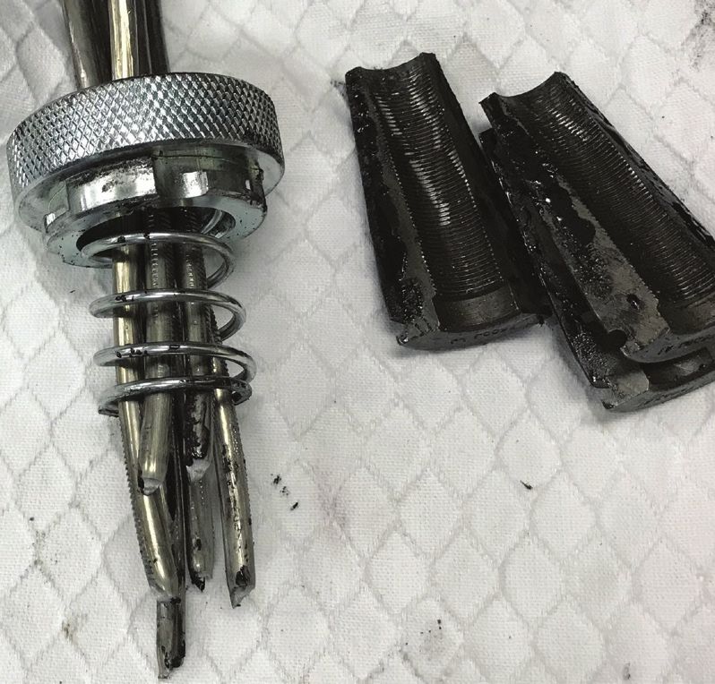
applicable for both. There is little information available for    mechanical properties of duplex Grades 2205 and 2304
the bond properties of stainless steel strands; therefore, the    prestressing strands.
bond of stainless steel strands needs to be evaluated.
                                                                  Results from previous studies have revealed that all tested
As with all new products, the lack of information on the          stainless steel strands, regardless of their type, had rounded
mechanical and bond properties of Grade 2205 duplex               stress-strain curves after the elastic modulus was deviated.
high-strength stainless steel (HSSS) strands will delay their     The degree of roundedness, ultimate stress, ultimate strain,
implementation in civil engineering applications despite their    and corrosion resistance varied among strand types. Although
desirable corrosion resistance properties. Also, the mechanical   Moser et al.10 did not report directly on the differences in
properties and stress-strain behavior of the HSSS strands need    roundedness of the stress-strain curves for the six types of
to be known.                                                      stainless steel strands that were studied, the degree of the
                                                                  roundedness can be identified in the report. The mechanical
This paper presents the mechanical properties of 0.6 in.          properties and stress-strain behavior of strands depend on
(15.2 mm) diameter HSSS strands. Twenty-five 0.6 in.              many factors, such as chemical composition, heat treatment,
diameter HSSS strands from two spools were tensile tested.        and level of cold work.13 The cold-drawing process is essen-
A stress-strain equation was developed for the HSSS strands.      tial to achieve high tensile strength.14 The early nonlinear
The proposed equation satisfies the Standard Specification        stress-strain behavior of stainless steel strands is likely due to
for Low-Relaxation, Seven-Wire, Grade 240 [1655], Stain-          the presence of residual stress from the cold-drawing process.2
less Steel Strand for Prestressed Concrete (ASTM A1114)5          Heat treatment reduces residual stresses, which increases the
requirements and results in a stress-strain curve similar to      tensile strength and improves the stress-strain relationship
the experimental data. This paper also evaluates the bond of      below yield;2 however, heat treatment reduces ultimate strain.
0.6 in. diameter HSSS strands determined by testing six HSSS      Thus, unlike carbon steel strands, stainless steel strands have
strands following the Standard Test Method for Evaluat-           low ultimate strain and stress and have a rounded stress-
ing Bond of Seven-Wire Steel Prestressing Strand (ASTM            strain curve with early nonlinearity. All previous research has
A1081).6 Experimental bond values of 0.6 in. diameter HSSS        concluded that Grade 2205 duplex HSSS is the best option for
strands were compared with values calculated using the            strands compared with other types of stainless steel because
proposed acceptance criteria by the PCI Strand Bond Task          of its high mechanical and corrosion resistance properties,
Group.7 This study is part of a larger research project where     which can potentially improve long-term performance of
0.6 in. diameter HSSS strands were used in the fabrication        bridge structures in extremely aggressive environments.
of several American Association of State Highway and
Transportation Officials (AASHTO) Type II girders; design,        Comparison of carbon steel
construction, and flexural behavior of the girders as well as     and stainless steel strands
transfer length of HSSS strands are discussed in detail in
other publications.8,9                                            The mechanical properties of stainless steel strands are differ-
                                                                  ent from those of carbon steel strands. The minimum required
A brief background on stainless steel                             mechanical properties of carbon steel strands are specified by
strands                                                           Standard Specification for Low-Relaxation, Seven-Wire Steel
                                                                  Strand for Prestressed Concrete (ASTM A416)15 for both
Multiple types of stainless steel strands have been devel-        Grade 250 and Grade 270 strands. The mechanical properties
oped, and researchers have experimentally evaluated their         specified by ASTM A41615 cannot be used for stainless steel
mechanical properties and corrosion resistance performance.       strands because stainless steel strands are made from different
Moser et al.2,10 conducted a preliminary investigation to eval-   alloys than carbon steel strands. Stainless steel strands are
uate the mechanical properties of six different HSSS wires        relatively new, and the need for a standard specification led
and their corrosion resistance performance in alkaline and        to the development of ASTM A1114,5 which was recently
carbonated concrete solutions. The six stainless steel wires      published. The new ASTM A11145 specifies the minimum
were austenitic Grades 304 and 316; martensitic Grade 17-7;       acceptable mechanical properties of Grade 240 stainless steel
and duplex Grades 2101, 2304 and 2205. Moser2 proved              strands. The decrease in the grade from 270 in ASTM A41615
that it is possible to obtain mechanical properties of carbon     to 240 in ASTM A11145 is attributed to the chemical com-
steel strand by tensile testing a single wire taken from the      position of the strand and the manufacturing process.2 Some
strand. Thus, Moser et al.2,10 performed the tensile tests on     alloying elements used to make stainless steel strands control
a single wire for all six specimens and engineering stress-       the ultimate tensile strength.
strain curves were plotted. The diameter of a single wire was
0.16 in. (4.1 mm), which is comparable to a single wire from      Table 1 lists the minimum requirements for ASTM A1114
a 0.5 in. (12.7 mm) diameter carbon steel strand. Mullins et      Grade 240 strands and comparably sized ASTM A416
al.11 evaluated the mechanical and corrosion resistance prop-     Grade 270 strands. ASTM A1114 provides mechanical prop-
erties of three different stainless steel strands (Grade 316,     erties for only two sizes of stainless steel strands, 0.52 and
Grade XM29, and duplex Grade 2205) with Grade 270                 0.62 in. (13.2 and 15.7 mm) diameter. The area and weight of
carbon steel strand as the control. Schuetz12 evaluated the       Grade 240 stainless steel strands are equal to their counterpart

                                                                                           PCI Journal | July–August 2021              67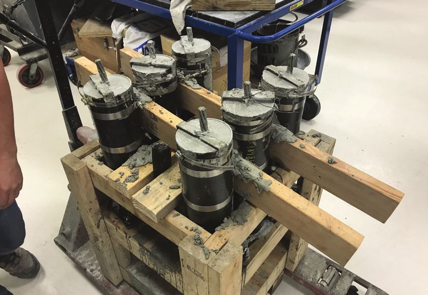
Table 1. Minimum required mechanical properties of strands
Parameter ASTM A416 Grade 270 ASTM A1114 Grade 240
Nominal diameter, in. 0.52 0.62 0.52 0.62
Area, in.2 0.167 0.231 0.167 0.231
Load at 1% extension, kip 40.5 56.52 36.1 49.86
Breaking strength, kip 45.0 62.8 40.1 55.4
Elongation, % 3.5 3.5 1.4 1.4
Weight of strand, lb/1000 ft 570 780 570 780
Note: ASTM A416 = Standard Specification for Low-Relaxation, Seven-Wire Steel Strand for Prestressed Concrete; ASTM A1114 = Standard Specification
for Low-Relaxation, Seven-Wire, Grade 240 [1655], Stainless Steel Strand for Prestressed Concrete. 1 in. = 25.4 mm; 1 ft = 0.305 m; 1 in.2 = 645.2 mm2;
1 lb = 0.454 kg; 1 kip = 4.448 kN.
Grade 270 carbon steel strands. Stainless steel strands have any visible defects. They were stored at the Florida Depart-
lower load at 1% extension, breaking strength, and elonga- ment of Transportation (FDOT) Structures Research Center
tion compared with carbon steel strands. The most significant and protected from oil, excessive bending, and any physical
difference between carbon steel and stainless steel strands is damage. A mill test certificate for each spool was provided by
elongation. The guaranteed elongation for stainless steel strands the manufacturer, specifying the mechanical properties and
is only 40% of that for carbon steel strands. stress-strain relationship of the HSSS strands. The mechanical
behavior of HSSS strands might vary from spool to spool for
The shape of the stress-strain curve for stainless steel strands multiple reasons, such as the wire rod used to make prestress-
is different from that for carbon steel strands. Carbon steel ing strands not being perfectly identical from heat to heat,
strands exhibit a linear plateau, whereas stainless steel strands chemistry variances of the elements alloyed, and processing
exhibit almost no strain hardening and have rounded behavior variances. Therefore, multiple samples from the two spools
in the plastic region (Fig. 1). The limited ductility in stainless were tensile tested. Both spools were produced by the same
steel strands significantly affects the design philosophy for manufacturer. The samples from the two spools are referred to
concrete members prestressed with stainless steel strands. as first spool and second spool throughout this paper.
Tensile tests Fifteen HSSS strand specimens were taken from the first
spool. Ten specimens were taken from the beginning of the
Specimen preparation spool. Then the strand in the spool was used to fabricate
several pretensioned concrete beams. Information regard-
Two new 0.6 in. (15.2 mm) diameter HSSS strand spools were ing fabrication and testing of those beams can be found in
received at different times in ideal condition: free of rust and another report.8 The other five specimens were taken from the
300
2000 300
2000
1750 275
250
250 1750
Tensile stress, MPa
1500
Tensile stress, MPa
225
Tensile stress, ksi
1500
Tensile stress, ksi
200
1250 200
175 1250
150 1000 150 1000
750 125
100 750
Carbon steel strands (ASTM A416) 100
Stainless steel strands (ASTM A1114) 500
75 Stainless steel strands (ASTM A1114) 500
Yield stress requirement (ASTM A1114)
50
Ultimate stress requirement (ASTM A1114) 250 50 Yield stress requirement (ASTM A1114)
250
25 Ultimate stress requirement (ASTM A1114)
0 0 0 0
0 0.5 1 1.5 2 2.5 3 3.5 4
0 0.2 0.4 0.6 0.8 1 1.2 1.4 1.6
Strain, % Strain, %
Figure 1. Comparison of stress-strain curves of stainless steel strands and carbon steel strands. Note: ASTM A416 = Standard
Specification for Low-Relaxation, Seven-Wire Steel Strand for Prestressed Concrete; ASTM A1114 = Standard Specification for
Low-Relaxation, Seven-Wire, Grade 240 [1655], Stainless Steel Strand for Prestressed Concrete.
68 PCI Journal | July–August 2021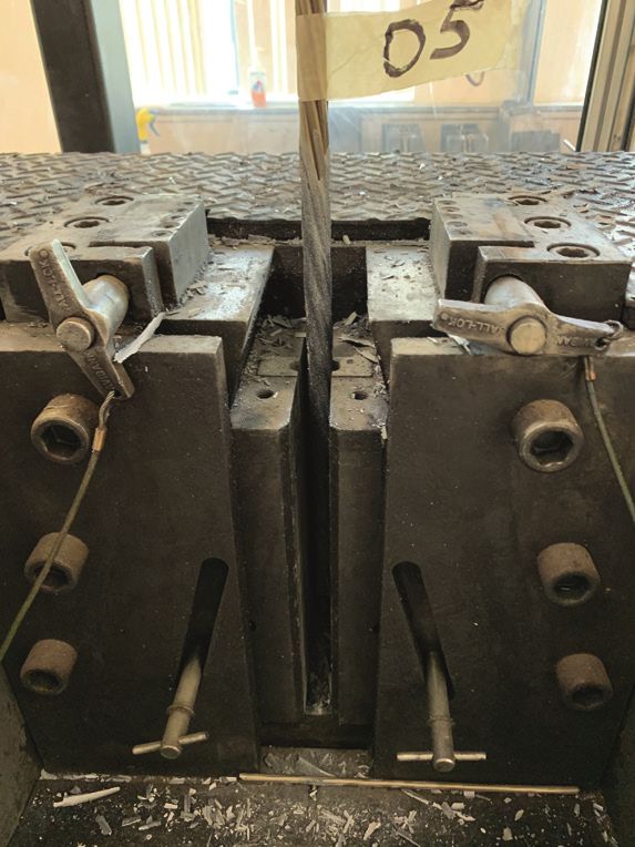
additional length of strand in the precasting bed remaining        er leaves it to the tester to decide which method is more suit-
after fabrication of the beams. Ten HSSS strand specimens          able. However, it does not allow the use of chuck devices as
were taken from the second spool. Five specimens were taken        a primary gripping device in the tensile tests. HSSS strands
directly from the spool, and the other five specimens were         exhibit grip slippage and complications with the gripping
taken from the strands in the precasting bed that remained         media, such as stress concentration and premature failure.
after beam fabrication. All specimens were sent to the FDOT        Therefore, the ends of most of the strands were coated with
State Materials Office (SMO) for tensile testing.                  high-modulus epoxy and 80 grit silicon carbide to create a
                                                                   friction grip and prevent grip slippage (Fig. 2). This coating
Several methods can be used to grip the strands for the            approach seems to be one of the best available methods to
tensile test. The type of strand and tensile testing machine       transfer force from the grips to HSSS strands because it typ-
determine which gripping method to use. Standard Test              ically eliminates failure at the strands’ ends. All specimens
Methods for Testing Multi-Wire Steel Prestressing Strand           were tensile tested using the grout coating approach except
(ASTM A1061)16 does not specify a single gripping method           for five specimens, which were taken directly from the first
for all types of strands and tensile testing machines but rath-    spool. Those specimens were tensile tested using chuck

              Epoxy coating applied at                Specimens prepared                    Seating the end of the
               the end of a specimen                   for tensile testing                   specimen in the grip

           Strand preloaded to be aligned            Extensometer attached                     Strand at failure
               and seated in the grips            to a strand to measure strain
                                                       up to 1% elongation

Figure 2. Preparation and testing of stainless steel specimens in tension. Note: Tensile tests were performed to determine the
mechanical properties and stress-strain behavior of the stainless steel strands. Tensile tests were performed at the Florida De-
partment of Transportation State Materials Office in Gainesville, Fla.

                                                                                           PCI Journal | July–August 2021            69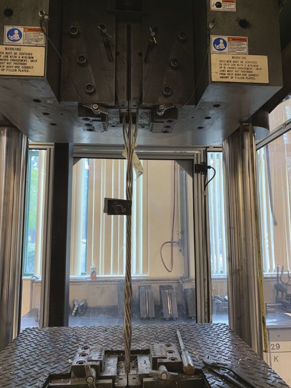
Table 2. Test matrix of the tensile test                                         up to about 1% extension with an accuracy of 0.01%, and then
                                                                                       it was removed to prevent possible damage, as Grade 2205
                               Number of specimens
                                                                                       HSSS strands have low ultimate strain. After the extensometer
          Source of                      Beginning                  Remaining          was removed, data collection was switched from the exten-
           strand                         of spool                    in bed           someter to the UTM and the specimen was reloaded. The
                                                                                       UTM calculates strain by measuring displacement between
           Testing               Grout              Chuck                 Grout        the machine’s crossheads.
           method               coating             devices              coating

      First spool                   5                 5                    5           Using chuck devices Chuck devices (wedges) are usually
                                                                                       used in the field for normal strand tensioning procedures; how-
      Second spool                  5                n/a                   5           ever, ASTM A106116 clearly states that chuck devices shall not
      Note: n/a = not applicable.                                                      be used in the tensile test as a primary gripping device. Because
                                                                                       stainless steel strands are relatively new to the construction
     devices as a primary gripping device to determine whether                         industry and to ensure that regular chuck devices can be used
     chuck devices can be used in the casting yard to tension                          to tension the HSSS strands in the casting yard, five 50 in.
     HSSS strands. Table 2 shows the test matrix of the tensile                        (1270 mm) HSSS strands were tensile tested using chuck de-
     tests in this experimental program.                                               vices as the primary gripping devices. The chuck devices were
                                                                                       attached to the ends of the strands and neither epoxy nor 80-grit
     Setup                                                                             silicon carbide was used to coat the ends of the strands. The
                                                                                       tensile tests were performed using a UTM. The strand was pre-
     Using grout coating approach A universal testing ma-                              loaded to 10% of breaking strength, and then an extensometer
     chine (UTM) was used for the tensile tests. The length of                         was attached. The UTM was unloaded at 1% extension to avoid
     each specimen was 50 in. (1270 mm), and the strand length                         damage when removing the extensometer. After the extensom-
     inserted in each grip was 8 in. (203 mm) (Fig. 2). This                           eter was removed, the data collection was switched to the UTM
     embedded length allowed for a full transfer of the load from                      and the strand was reloaded again until failure.
     the grips to the strand. A preload of about 10% of breaking
     strength was applied to align the strand and seat the ends in                     Results
     the grips (Fig. 2). After the strand was aligned and tight, a
     24 in. (610 mm) extensometer was attached to the strand,                          Using grout coating approach Tensile tests were performed
     leaving 5 in. (127 mm) clear distance between the jaws and                        on twenty 0.6 in. (15.2 mm) diameter HSSS strands, 10 from
     the extensometer (Fig. 2). The extensometer measured strain                       each spool. All specimens were tensioned until breakage, which

      Table 3. Statistical summary of test results for specimens from the first spool

                                        Yield strength         Yield                                                                             Elastic
      Specimen        Specimen                                             Breaking      Ultimate         Yield strength
                                                                                                                             ,%   Elongation,
                                        (load at 1% ex-       stress                                         Specified                          modulus,
        type           number                                              load, kip   stress fpu, ksi   breaking strength            %
                                         tension), kip        fpy, ksi                                                                             ksi

                           1                52.52             228.34           60.25       261.93                94.80               1.87        24,100

                           2                52.61             228.72           60.35       262.40                94.96               1.85        24,500
      Beginning
                           3                52.50             228.27           60.12       261.40                94.76               1.83        24,600
      of spool
                           4                51.72             224.86           60.31       262.22                93.36               1.89        23,900

                           5                52.47             228.11           60.07       261.16                94.71               1.86        24,400

                           6                53.41             232.23           60.14       261.47                96.41               1.76        25,200

                           7                53.88             234.27           59.99       260.81                97.26               1.69        25,900
      Remaining
                           8                53.43             232.32           60.36       262.43                96.44               1.80        25,200
      in bed
                           9                53.42             232.25           60.01       260.89                96.43               1.75        25,600

                           10               53.41             232.23           60.11       261.35                96.41               1.78        25,800

      Average                               52.94             230.16           60.17       261.61                95.55               1.81        24,920

      Standard deviation                    0.667             2.900            0.139       0.602                  1.14               0.064          716

      Note: 1 kip = 4.448 kN; 1 ksi = 6.895 MPa.

70           PCI Journal | July–August 2021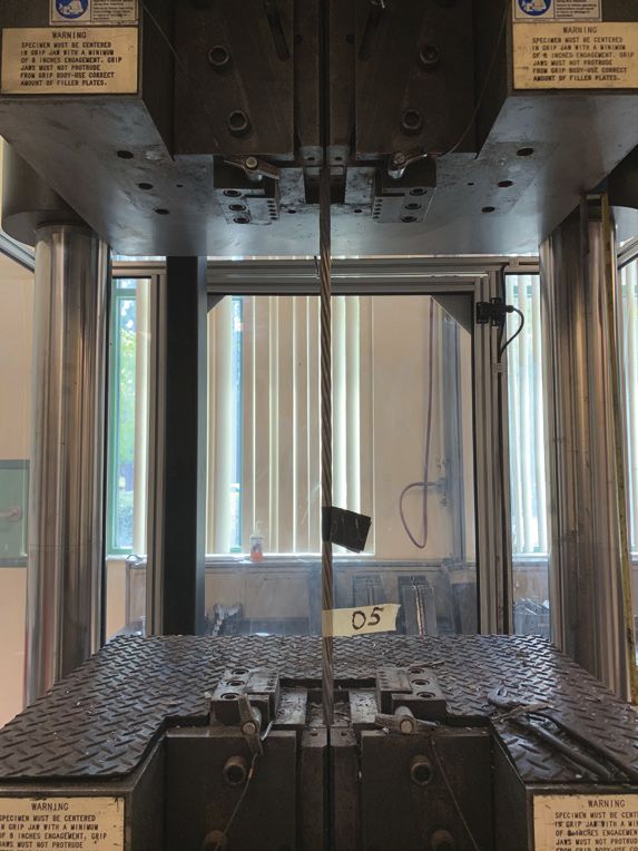
Table 4. Statistical summary of test results for specimens from the second spool
Yield strength Yield Ultimate Elastic
Specimen Specimen Breaking Yield strength
,% Elongation,
(load at 1% ex- stress stress fpu, Specified modulus,
type number load, kip breaking strength %
tension), kip fpy, ksi ksi ksi
1 51.06 223.96 56.87 249.42 92.12 1.62 24,500
Beginning 2 50.62 222.02 56.66 248.51 91.37 1.63 24,200
of spool 3 50.18 220.10 56.77 248.97 90.58 1.71 24,200
4 50.58 221.83 56.41 247.42 91.30 1.59 24,600
5 51.40 225.44 56.95 249.80 92.78 1.63 25,300
Remaining 6 52.06 228.33 57.12 250.52 93.97 1.59 25,300
in bed 7 51.21 224.61 57.02 250.10 92.44 1.64 24,800
8 51.84 227.37 57.22 250.97 93.57 1.66 25,400
Average 51.12 224.21 56.88 249.46 92.27 1.63 24,788
Standard deviation 0.645 2.831 0.262 1.150 1.09 0.036 494
Note: 1 kip = 4.448 kN; 1 ksi = 6.895 MPa.
is defined as the failure state. Failure of all strands happened Figure 3 shows stress-strain plots of the tested HSSS
at one end, close to the jaw (Fig. 2). The failure of all strands strands. Note that the stress-strain behavior is different
was categorized as pure rupture. Statistical summaries of tested between specimens from the first spool and second spool.
strands are presented in Tables 3 and 4 for specimens from These differences can likely be attributed to multiple rea-
the first and second spools, respectively. Experimental results sons, such as chemistry variances of the elements alloyed,
of two strands from the second spool were excluded from the processing variances, and the wire rod used to make the
summary in Table 4. The first specimen was excluded because prestressing strands not being perfectly identical from heat
the length of the specimen was shorter than the required length to heat. Tensile test results showed that the HSSS strands
and the extensometer could not be installed to measure elonga- exhibit early nonlinearity compared with carbon steel and a
tion. The second specimen was excluded because the specimen rounded stress-strain curve after the elastic modulus slope
was not seated perfectly in the grips, which significantly affect- is deviated. Figure 3 shows a small drop in stress at about
ed the experimental results. The measured area for the strand 1% strain. This drop occurred due to unloading the strand to
from the first spool was 0.230 in.2 (148 mm2), and the measured remove the extensometer. It should be noted that this drop
area from the second spool was 0.228 in.2 (147 mm2). was inevitable, but it could have been minimized by more
quickly removing the extensometer and reloading the UTM.
After the drop, the strains were measured based on the
crosshead displacement.
300
2000
250 1750 Table 5 gives the mechanical properties for 0.6 in. diame-
1500
ter high-strength stainless steel strands according to ASTM
Tensile stress, MPa
Tensile stress, ksi
200 A11145 requirements, FDOT specification requirements,17
1250
mill certificates provided by the manufacturer for each spool,
150 1000 and average experimental results. All specimens from the
100
750 first and second spools satisfied ASTM A11145 and FDOT re-
500
quirements,17 except for the area requirements. The measured
50 Specimens from first spool
average area of the specimens from both spools was slightly
250
Specimens from second spool lower than the required value; the difference is insignificant.
0 0 Note that the specified diameter of the tested specimens from
0.00 0.25 0.50 0.75 1.00 1.25 1.50 1.75 2.00
Strain, %
both spools was 0.6 in. (15.2 mm), whereas ASTM A11145
provides minimum required mechanical properties for 0.62 in.
(15.7 mm) diameter strands. The two spools used in the study
Figure 3. Stress-strain curves of the stainless steel strands were manufactured before the publication of ASTM A1114.5
from the tensile tests. Note: This figure can be used to de- Specimens from the first spool had higher yield and breaking
termine mechanical properties of the tested stainless steel strengths, elongation, and elastic modulus than those from the
strands. second spool.
PCI Journal | July–August 2021 71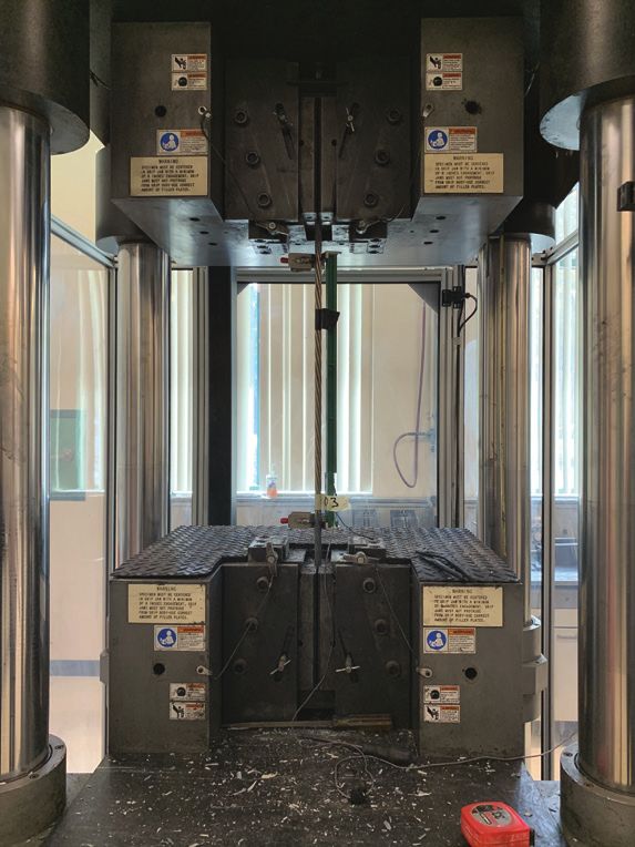
Table 5. Mechanical properties for 0.6 in. diameter high-strength stainless steel strands
Load at 1% Elastic
Breaking Ultimate Elongation,
Area, in.2 extension, modulus,
strength, kip stress fpu, ksi %
kip ksi
Standard ASTM A1114 0.2310 ≥ 49.86 ≥ 55.40 ≥ 240 ≥ 1.4 n/a
requirements FDOT 0.2310 ≥ 49.86 ≥ 55.40 ≥ 240 ≥ 1.4 n/a
Manufacturer’s
0.2328 52.92 59.76 256.65 1.90 24,300
data
First spool
Average
0.2300 52.94 60.14 261.61 1.81 24,950
tensile tests
Manufacturer’s
0.2306 50.59 55.47 240.56 1.60 23,900
data
Second spool
Average
0.2280 51.12 56.88 249.46 1.63 24,750
tensile tests
Note: ASTM A1114 = Standard Specification for Low-Relaxation, Seven-Wire, Grade 240 [1655], Stainless Steel Strand for Prestressed Concrete; FDOT =
Florida Department of Transportation; n/a = not applicable. 1 in.2 = 645.2 mm2; 1 kip = 4.448 kN; 1 ksi = 6.895 MPa.
Tensile test of a specimen Failure of the specimen Notching effect of grips on
using chuck devices at the chuck the stainless steel strands
Figure 4. Preparation and testing of stainless steel strands in tension using chuck devices. Note: Tests were performed at the
Florida Department of Transportation State Materials Office in Gainesville, Fla.
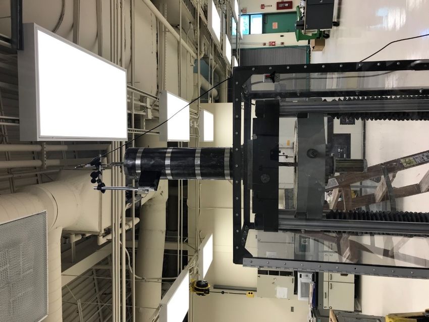
Using chuck devices Tensile tests were performed on five sion, ultimate strain, and modulus of elasticity) when strands
0.6 in. (15.2 mm) diameter HSSS strands from the first spool. were tensile tested with chuck devices. This is clear evidence
Figure 4 shows a stainless steel strand being tensile tested that using chuck devices for tensile tests does not produce the
using chucks as the primary gripping devices. Failure of all five full capacity of strands and should not be done, as stated by
specimens happened at one end at the point where the chucks ASTM A1061.16 The behavior of the strands before yielding
gripped the strands. Figure 4 also shows the notching effect was not significantly affected by using the chuck devices com-
of the grips, which resulted in failure of the strand. Figure 5 pared with the behavior after yielding (Fig. 5). Usually strands
shows the stress-strain curves of specimens tensile tested using in the casting bed are tensioned within their elastic limit, below
grout coating and chuck devices. Table 6 reports the average yield strength. Therefore, chuck devices (wedges) can be used
mechanical properties of tested strands. A reduction in all to initially tension Grade 2205 HSSS strands for prestressed
parameters was observed (breaking strength, load at 1% exten- concrete member fabrication.
72 PCI Journal | July–August 2021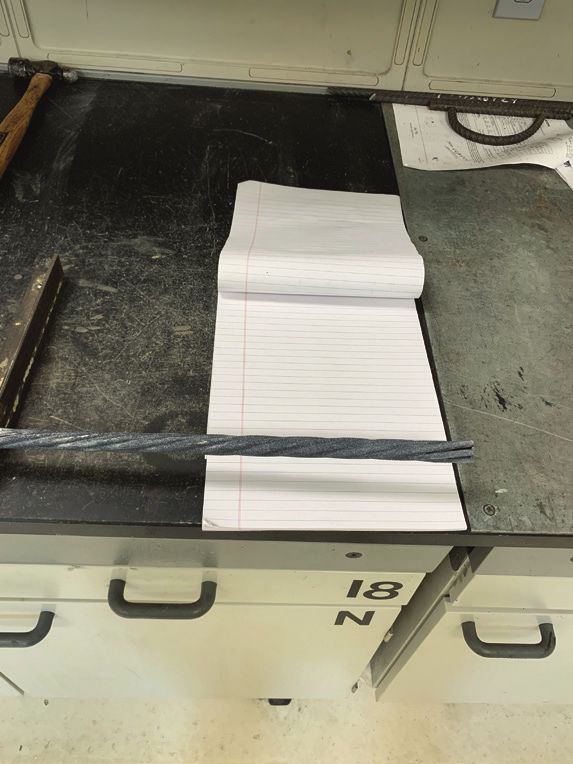
Table 6. Mechanical properties of high-strength
300 stainless steel strands tested using grout coating and
2000
chuck devices
250 1750
Using grout Using chuck Reduction,
1500 Parameters
Tensile stress, MPa
coating devices %
Tensile stress, ksi
200
1250
150 1000 Area, in.2 0.2328 0.2328 0
750 Load at 1%
100
52.94 51.92 1.92
500 extension, kip
50 Grout coating
250
Chuck devices Breaking
0 0
60.17 57.79 3.95
strength, kip
0.00 0.25 0.50 0.75 1.00 1.25 1.50 1.75 2.00
Strain, %
Elongation, % 1.81 1.60 11.60
Elastic
Figure 5. Stress-strain curves of stainless steel strands tested 24,950 23,900 4.09
modulus, ksi
in tension using grout coating and chuck devices. Note: This
figure shows the influence of using chuck devices on the me-
Note: 1 in.2 = 645.2 mm2; 1 kip = 4.448 kN; 1 ksi = 6.895 MPa.
chanical properties of stainless steel strands.
Yield strength There are multiple methods to determine • The HSSS strands kept their shape as bent on the spool,
the yield strength of prestressing strands. The most com- which resulted in difficulties seating both ends of the
mon methods are the extension under load (EUL) and offset specimen in the top and bottom grips.
methods.18 ASTM A41615 and ASTM A11145 propose the
EUL method for seven-wire prestressing strand. Those ASTM • The location of the break of the HSSS specimens was
standards define the yield strength as the load when the total close to the grip in all specimens tested using the coating
strain reaches 1%, and the yield strength must be at least approach, while the carbon steel strands broke at random
90% of the specified breaking strength, which is equal to locations.
55.4 kip (246 kN) for 0.62 in. (15.7 mm) diameter stainless
steel strands. Tables 3 and 4 show that all specimens from the • The epoxy coating (Fig. 2) peeled from the HSSS speci-
first spool and the second spool adequately met the 90% yield mens.
strength requirement. Specimens from the first spool had an
average yield strength of 95.55% of the specified breaking • The HSSS specimens failed more quickly than the carbon
strength and standard deviation of 1.14% (Table 3). Table 4 steel strands, and the plastic strain was much smaller than
shows that specimens from the second spool had an average that of the carbon steel strands.
yield strength of 92.27% of the specified breaking strength
and standard deviation of 1.09%. • Special attention was needed when removing the exten-
someter after reaching 1% extension because the HSSS
The offset method defines the yield stress as the intersection specimens might break while removing the extensometer
of the stress-strain curve with a line that starts at a specified due to its short plastic strain.
strain value and runs parallel to the linear region of the stress-
strain curve. Eurocode 2: Design of Concrete Structures: Part Stress-strain model
1-1: General Rules and Rules for Buildings19 specifies the
initial strain value as 0.1%. This method is called the 0.1% Background
offset method. The 0.2% offset method is recommended by
the Korea Concrete Institute,20 which specifies the initial The stress-strain behavior of stainless steel strands is dif-
strain value as 0.2%. Schuetz12 suggests using the 1.2% ex- ferent from that of carbon steel strands. Therefore, a new
tension method or 0.2% offset method to determine the yield stress-strain equation needs to be developed. The stress-
strength of Grade 2205 stainless steel strands. In this research, strain formula is necessary for strength design and numer-
yield strengths calculated using the 1.2% extension method or ical analysis of prestressed concrete members. A widely
the 0.2% offset method were higher than 90% of the breaking accepted method for describing the stress-strain behavior
strength, which satisfies the 90% yield strength requirement of a material is the Ramberg-Osgood model.21 The original
of ASTM A1114.5 model was developed for aluminum alloys and was not valid
for materials with highly nonlinear stress-strain relation-
Differences in tensile testing between carbon steel ships. Since the development of the original model, many
and HSSS strands The professional technician who per- researchers have modified the model either for different
formed the tensile tests at FDOT SMO reported multiple materials or to better fit experimental tests. One of the
differences between tensile testing of carbon steel strands and most widely used analytical formulas, known as the power
HSSS strands. The differences are as follows: formula, was derived from the modified Ramberg-Osgood
PCI Journal | July–August 2021 73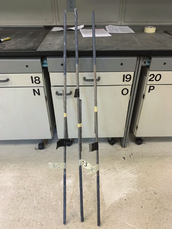
function. The power formula was proposed by Mattock22 Devalapura and Tadros24 studied 56 stress-strain curves for
and has been proved suitable for highly nonlinear materials. low-relaxation Grade 270 carbon steel strand. Half of the
It includes four curve-fitting constants, as shown in Eq. (1). stress-strain curves were obtained from the manufacturers,
The methodology behind this formula is to divide the stress- whereas the other half were obtained from testing by Deva-
strain curve into two straight lines connected by a curve. The lapura and Tadros.24 The specimens were made from different
first line is for the elastic region, and the second line is for types of steel and were tested by different machines. A statis-
the inelastic region. As long as the actual stress-strain curve tical lower-bound curve was derived from the 56 curves. The
is available, the four curve-fitting variables can be calcu- outcome of the study was proposed curve-fitting constants
lated. The elastic modulus E is determined from the elastic for the power formula for 0.5 in. (12.7 mm) diameter low-re-
region of the strand stress-strain curve. A detailed procedure laxation carbon steel strands.24 The proposed power formula
for calculating curve-fitting constants for the power formula curve was as close as possible to the experimental low-
is given in Collins and Mitchell.23 er-bound curve and satisfied the yield strength requirements
of ASTM A416.15 Collins and Mitchell23 proposed curve-fit-
⎧ ⎫
⎪⎪ ⎪⎪ ting constants for the power formula for 0.6 in. (15.2 mm)
1− A
σ = E × ε ⎨A+ 1/C ⎬
(1) diameter Grade 270 carbon steel strand.
⎪
⎪⎩ ⎢⎣ (
⎡1+ B × ε C ⎤ ⎪
⎥⎦ ⎪⎭ )
The power formula is not limited to specific strand diame-
where ters. Morcous et al.25 recently proposed a power formula for
0.7 in. (17.8 mm) diameter Grade 270 carbon steel strand.
σ = stress in strand The curve-fitting constants for the proposed power formula
in the Morcous et al.25 study were calculated after testing 40
ε = strain in strand strands from two different producers and using two differ-
ent machines.
A = curve-fitting constant
All proposed power formulas result in a conservative curve
B = curve-fitting constant that lies below the actual stress-strain curves. This is mainly
because the proposed power formulas were developed to fit the
C = curve-fitting constant lower-bound curve of tested strands. The PCI Design Hand-
book: Precast and Prestressed Concrete26 provides approximate
Researchers have developed power formulas for all available stress-strain equations for seven-wire low-relaxation strands.
low-relaxation carbon steel strand sizes. Table 7 shows power The PCI equations are divided into two parts: the first part is for
formulas for three sizes of Grade 270 carbon steel strand. the elastic region, and the second one is for the plastic region.
Table 7. Stress-strain equations for low-relaxation Grade 270 carbon steel strands
Author Diameter, in. Modulus of elasticity, ksi Proposed stress-strain equation
⎧ ⎫
Devalapura and ⎪⎪ 0.969 ⎪⎪
0.5 28,500 σ = E × ε ⎨0.031+ 1/7.36 ⎬
Tadros (1992)
⎡1+ 112.4 × ε( ) ⎤
7.36
⎪ ⎪
⎪⎩ ⎣⎢ ⎦⎥ ⎪⎭
⎧ ⎫
Collins and Mitch- ⎪⎪ 0.975 ⎪⎪
0.6 29,000 σ = E × ε ⎨0.025 + 1/10 ⎬
ell (1991)
⎡1+ 118 × ε ( ) ⎤ ⎪
10
⎪
⎪⎩ ⎢⎣ ⎥⎦ ⎪⎭
⎧ ⎫
⎪ ⎪
⎪ ⎪
Morcous et al. ⎪ 0.98 ⎪
0.7 28,500 σ = E × ε ⎨0.02 + 1/7.33 ⎬
(2011)
⎪ ⎡ ⎛ ⎞ ⎤
7.33
⎪
⎪ ⎢1+ ⎜ E × ε ⎟ ⎥ ⎪
⎪ ⎢ ⎝ 1.03× f py ⎠ ⎥ ⎪
⎩ ⎣ ⎦ ⎭
Note: E = modulus of elasticity of strand; fpy = specified yield stress of strand; ε = strain in strand; σ = stress in strand. 1 in. = 25.4 mm; 1 ksi = 6.895 MPa.
74 PCI Journal | July–August 2021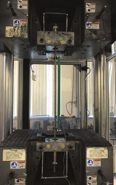
Proposed stress-strain model
                                                                                                          300
                                                                                                                                                                            2000
The format of the modified Ramberg-Osgood function, given
in Eq. (1), was used to develop the stress-strain models of the                                           250                                                               1750

two HSSS spools.                                                                                                                                                            1500

                                                                                                                                                                                   Tensile stress, MPa
                                                                                                          200

                                                                                    Tensile stress, ksi
                                                                                                                                                                            1250
Tensile tests As mentioned, ten 50 in. (1270 mm) long                                                     150                                                               1000
specimens from each spool were tested in direct tension. The
                                                                                                                                                                            750
elastic modulus E was determined from the experimental data                                               100                Specimen from first spool
                                                                                                                             Specimen from second spool                     500
following ASTM A1061,16 and the three coefficients (A, B,                                                 50
                                                                                                                             Proposed equation

and C) in Eq. (1) were calculated to obtain a best fit with the                                                              Yield stress requirement (ASTM A1114)
                                                                                                                             Ultimate stress requirement (ASTM A1114)
                                                                                                                                                                            250

lower-bound curve of the tested strands. Table 8 summarizes                                                0                                                                0
                                                                                                                0   0.5           1                1.5                  2
the proposed coefficients.                                                                                                   Strain, %

Stress-strain equation for design ASTM A11145 require-
ments represent the minimum guaranteed mechanical properties                 Figure 6. Comparison of the proposed equation for a stress-
                                                                             strain model with experimental stress-strain behavior of stain-
for stainless steel strands. Thus, the proposed stress-strain equa-
                                                                             less steel strands. Note: ASTM A1114 = Standard Specification
tion for design purposes should represent the ASTM A11145                    for Low-Relaxation, Seven-Wire, Grade 240 [1655], Stainless
minimum requirements and have the same shape as the curve for                Steel Strand for Prestressed Concrete.
the tested specimens. This means that for 1% strain and 1.4%
strain, the proposed equation should result in a stress of 216               stainless steel strands that have mechanical properties greater
and 240 ksi (1490 and 1650 MPa), respectively. The curve-fit-                than the minimum requirements of ASTM A1114.5
ting constants in Eq. (1) were derived to adequately match the
ASTM A11145 requirements and have the same stress-strain                     Strand bond tests
curve as the tested specimens. The proposed stress-strain equa-
tion for 0.6 in. (15.2 mm) diameter HSSS strands is given in                 A test procedure to measure the bond of prestressing strand
Eq. (2).                                                                     is provided by ASTM A1081,6 which was adopted from
                                                                             the North American Strand Producers,27 where the strand
               ⎧                                 ⎫
               ⎪⎪                                ⎪⎪                          is pulled out from a sand-cement mortar. In this study, the
                             0.94
σ = 24,000 × ε ⎨0.06 +                   1/6.45 ⎬
                                                    (2)                     ASTM A10816 test method was used to evaluate the bond of
                ⎪
                ⎪⎩     ⎣⎢
                                  (
                       ⎡1+ 101× ε 6.45 ⎤
                                       ⎦⎥
                                             )  ⎪
                                                ⎪⎭
                                                                             0.6 in. (15.2 mm) diameter HSSS strands in mortar.

Figure 6 provides a visual representation of the proposed                    Specimen preparation
equation along with two stress-strain sample curves from
the experimental results, one from each spool. The proposed                  The strand bond test was performed according to
equation fits the lower-bound curve of the tested strands in the             ASTM A1081 protocol.6 The test requires a minimum of six
elastic region. This was achieved by taking the elastic modu-                strands and 15 mortar cubes. Six HSSS strands were taken
lus equal to 24,000 ksi (165,500 MPa). The proposed equation                 from the first spool in as-received condition and protected
in the plastic region is parallel to the shape of the curves for             from foreign substances. Six specimens were prepared by
the two spools in the plastic region. The proposed equation                  casting sand-cement mortar in a steel pipe around a single 0.6
is conservative and underestimates the strand behavior of the
two spools. It is conservative compared with the actual behav-
ior of the HSSS strands because manufacturers will produce

 Table 8. Coefficients of modified Ramberg-Osgood
 function for tested high-strength stainless steel
 strands

                                             Coefficients

     Specimen
                                A                 B                C
   identification

 First spool                  0.065              100               6.5

 Second spool                 0.050              102               7.0

 Note: A = curve-fitting constant for stress-strain power formula; B =
 curve-fitting constant for stress-strain power formula; C = curve-fitting
 constant for stress-strain power formula.                                   Figure 7. Stainless steel specimens prepared for bond test.

                                                                                                                          PCI Journal | July–August 2021                                                 75
LVDT
Dead end LVDT
2.5 in. (64 mm)
Dead end
Magnets to
hold LVDT
Magnets to
Steel tube hold LVDT
Steel tube
Steel plate
Strand 18 in. (450 mm) Neoprene
pad
Mortar
Bond breaker
Live end
Steel plate
2 in. (50 mm)
Chuck
Neoprene pad
Crosshead apply
downward force
to chuck
Figure 9. Specimen setup for standard test for strand bond.
Note: LVDT = linear variable displacement transducer.
edited
nected to the gripping device where the force was applied. A
linear variable displacement transducer was mounted at the
Chuck
dead end to measure displacement. The applied displacement
Live end
rate of the gripping device was 0.1 in./min (2.5 mm/min),
and the loading rate did not exceed 8500 lb/min (38 kN/min).
Figure 9 shows the testing apparatus used for the standard test
for strand bond.
Figure 8. Test setup for the bond strength test following Results
ASTM A1081. Note: Bond strength tests were performed to
determine the bond strength of stainless steel strands. Bond
strength tests were performed at the Florida Department
Strand bond is defined as the pullout force at the live end
of Transportation State Materials Office in Gainesville, Fla. that displaces the dead end of the strand by 0.1 in. (2.5 mm)
ASTM A1081 = Standard Test Method for Evaluating Bond of (Fig. 9). Per ASTM A1081,6 three mortar cubes shall be tested
Seven-Wire Steel Prestressing Strand; LVDT = linear variable each hour at 22 to 26 hours after casting until they reach
displacement transducer. 1 in. = 25.4 mm.
an average compressive strength of 4500 to 5000 psi (31 to
in. (15.2 mm) diameter HSSS strand (Fig. 7). The steel tube 34 MPa), after which strand bond tests can be performed. Mor-
was 5 in. (127 mm) in diameter and 24 in. (610 mm) tall. A 2 tar mixture proportions were validated before the experiment,
in. (50 mm) long steel breaker was placed around the strand at and the mortar was expected to have a compressive strength of
the bottom of the steel tube immediately above the steel plate 4500 to 5000 psi at 24 hours. Mortar strength has an influ-
(Fig. 8). This steel breaker was used to debond the strand and ence on the bond of the strand. Figure 10 shows the average
reduce the confinement pressure acting on the strand. The compressive strength results of three mortar cubes and shows
specimens were cured in an environmental chamber until test- that the average hourly compressive strength of the mortar
ing. The dimensions of the mortar cube were 2 × 2 × 2 in. (50 cube sets increased over time. The average hourly compressive
× 50 × 50 mm). Bond tests of strands were performed by pro- strength of three mortar cubes for each group did not pass the
fessional technicians at the FDOT SMO in Gainesville, Fla. minimum required compressive strength of ASTM A1081,6
which is 4500 psi (31 MPa). The average compressive strength
Setup 26 hours after casting was 4452 psi (30.7 MPa), which was
98.93% of the minimum required strength. A mean mortar
Figure 8 shows the schematic test setup used for the strength less than 4500 psi is acceptable by ASTM A10816 if
ASTM A1081 bond test. The live end of the strand was con- the bond test result exceeds a minimum threshold value. Thus,
76 PCI Journal | July–August 20215500
Displacement, mm
5000 35
0 2 4
Required 24000
4500 100
30
Compressive strength, MPa
4401 4402 4452
Compressive strength, psi
4000 4121 4195 20000
25 80
3500
Pull-out force, kN
Pull-out force, lbf
16000
3000 20 60
2500 12000
15 First strand
2000 40
8000 Seond strand
1500 Third strand
10
Fourth strand 20
4000
1000 Fifth strand
5 Sixth strand
500 0 0
0.00 0.05 0.10 0.15 0.20
0 0
22 23 24 25 26 Displacement, in.
Time after casting concrete, hours
Figure 10. Compressive strength of concrete mortar cubes for Figure 11. Pullout test results of 0.6 in. diameter high-strength
bond strength tests of stainless steel strands. stainless steel strands. Note: 1 in. = 25.4 mm.
the strand bond test was continued despite the minor under- six strands be 14.00 kip (62.3 kN), with no strand having a
strength of the mortar. pullout value less than 12.00 kip (53.4 kN) at 0.1 in. (2.5 mm)
displacement at the dead end. The second criterion is that the
The bond tests of strands were started 26 hours after mortar ultimate (high bond) recommended average pullout value
casting, and six HSSS strands were tested. Each test was from six strands be 18.00 kip (80.1 kN), with no strand having
terminated after the strand slip exceeded 0.1 in. (2.5 mm) a pullout value less than 16.00 kip (71.2 kN). Note that those
at the dead end, in accordance with ASTM A1081,6 and the acceptance bond threshold values are for 0.5 in. (12.7 mm)
strand bond was taken as the average pullout force of the six diameter Grade 270 carbon steel prestressing strand conform-
strand specimens. Force-slip displacements were measured ing to ASTM A416.15 For strands with either larger diameter
during the test. The pullout force at the chuck at the live end or different grades, the PCI task group proposed an equation,
was measured concurrently with the movement of the strand which is given in Eq. (3).
at the dead end. Figure 11 illustrates the force-displacement
results for the six strands. The minimum and average pull- (Pullout value)other sizes and grades =
out force at 0.1 in. displacement were 15.80 and 17.88 kip f pu
(70.3 and 79.5 kN), respectively. The peak tensile force was (Pullout value)0.5 in. × 2 × db × (3)
reached when the slip displacement at the dead end was about 270
0.0223 in. (0.566 mm) (Fig. 11). The minimum and average where
peak forces were 16.30 and 18.63 kip (72.5 and 82.9 kN),
which were about 3% and 4% greater than the minimum and db = diameter of strand
average pullout forces at 0.1 in. (2.5 mm) displacement at the
dead end, respectively. fpu = specified ultimate tensile stress of strand
ASTM A10816 does not specify a minimum threshold value Even though the recommended bond values were proposed for
for the bond of strand. In 2020, the PCI Strand Bond Task carbon steel strands conforming to ASTM A416,15 they were
Group7 recommended two acceptance bond threshold criteria used here for HSSS strand conforming to ASTM A1114.5
for ASTM A1081.6 The first criterion is that the minimum In this study, the diameter and specified tensile strength for
recommended average ASTM A10816 pullout value from HSSS strand are 0.6 and 240 ksi (15.2 and 1650 MPa), re-
Table 9. Comparison of experimental results with values recommended by PCI Strand Bond Task Group
Pullout force at 0.1 in. Ultimate pullout force
displacement, kip Experiment (high bond), kip Experiment
PCI PCI
Experiment PCI Experiment PCI
Minimum 15.80 12.80 1.23 16.30 17.07 0.96
Average 17.88 14.93 1.20 18.63 19.20 0.97
Note: 1 in. = 25.4 mm; 1 kip = 4.448 kN.
PCI Journal | July–August 2021 77spectively. Using Eq. (3), the minimum recommended average • The stress-strain relationship of HSSS strands is fun-
pullout value for 0.6 in. diameter Grade 240 HSSS strand is damentally different from that of carbon steel strands.
14.93 kip (66.4 kN), with no strand having a pullout value The HSSS strands have early nonlinearity with a round-
less than 12.80 kip (56.9 kN), and the ultimate (high bond) ed stress-strain curve in the plastic region. The HSSS
recommended average pullout value for 0.6 in. diameter strands exhibit almost no strain hardening compared
Grade 240 HSSS strand is 19.20 kip (85.4 kN), with no strand with carbon steel strands. Compared with carbon steel
having a pullout value less than 17.07 kip (75.9 kN). strands, the currently available HSSS strands have lower
ultimate strain and stress and elastic modulus. The most
Table 9 reports the pullout values obtained experimentally significant difference is in the elongation. The minimum
and those calculated using the approach proposed by the required elongation of the HSSS strands is only 40% of
PCI Strand Bond Task Group.7 The minimum and average that of the carbon steel strands.
experimental ASTM 10816 pullout values were 23.4% and
19.8% greater than the recommended values calculated using • The stress-strain equation for prestressing strand is
the PCI Strand Bond Task Group recommendations. Another essential for the strength design and numerical analysis of
comparison can be made with the ultimate (high bond) pullout prestressed concrete members. A stress-strain equation is
values measured experimentally. The minimum and average proposed for the 0.6 in. diameter HSSS strands. The pro-
peak forces (high bond ASTM A1081 value) were 95.5% and posed equation satisfies the ASTM A11145 requirements,
97.0%, respectively, of the recommended values calculated fits lower-bound curves of the tested strands in the elastic
using the PCI Strand Bond Task Group recommendations. region, and has a stress-strain shape similar to those of
Note that the PCI Strand Bond Task Group specified that the tested strands in the plastic region.
either the minimum ASTM A1081 value or the high bond
ASTM A1081 shall be satisfied. Therefore, it can be conclud- • Five 0.6 in. HSSS strands were tensile tested using chuck
ed that the 0.6 in. (15.2 mm) HSSS strand used in this study devices as the primary gripping devices. The objective
has an acceptable bond with concrete. of these tests was to verify that regular chuck devices
can be used to tension HSSS strands in the casting yard.
Conclusion Experimental results showed that the mechanical proper-
ties of the HSSS strands are not significantly affected in
The use of stainless steel strands may enhance the durability the elastic region when chuck devices were used in the
of prestressed concrete members due to their high corrosion tensile tests. Thus, regular chuck devices can be used in
resistance. Many types of stainless steel strands have been the casting yard to tension HSSS strands. This conclusion
developed, but researchers have found that Grade 2205 du- is limited to straight strands; harped strands or multi-
plex HSSS strand is the best option due to its high mechan- ple-strand tendons need further study.
ical and corrosion-resistance properties. This paper presents
the experimental results of tensile and pullout testing to • Bond of the 0.6 in. diameter HSSS strands was evaluated
determine the mechanical and bond properties of 0.6 in. following ASTM A1081.6 The minimum and average
(15.2 mm) diameter Grade 2205 HSSS strands. The follow- pullout forces at 0.1 in. (2.5 mm) end slip of six strands
ing conclusions were made: were 15.80 and 17.88 kip (70.3 and 79.5 kN), respec-
tively. The minimum and average peak pullout forces of
• Twenty 0.6 in. diameter HSSS strands from two spools six strands were 16.30 and 18.63 kip (72.5 and 82.9 kN),
were tensile tested to determine the mechanical proper- respectively, which were about 3% and 4% greater than
ties of the strand. The stress-strain behavior of specimens the minimum and average pullout forces at 0.1 in. end
from the two spools was different. The difference can be slip displacement, respectively. The peak pullout forces
attributed to multiple factors, such as the wire rod used occurred when end slip displacement at the dead end was
to make prestressing strands not being perfectly identical about 0.0223 in. (0.566 mm).
from heat to heat, chemistry variances of the elements
alloyed, and processing variances. • Minimum threshold values for strand bond are not specified
in ASTM A1081.6 In 2020, two acceptance bond threshold
• The most recent ASTM A11145 specifies the minimum criteria were recommended by the PCI Strand Bond Task
mechanical requirements of Grade 240 stainless steel Group7 for ASTM A1081.6 Experimental pullout forces
strands. Specimens from both spools tested satisfied the of 0.6 in. diameter HSSS strands at 0.1 in. end slip were
minimum requirements specified by ASTM A1114,5 except greater than the recommended values calculated using the
for the area requirement. The measured areas of the tested PCI Strand Bond Task Group equation; however, experi-
specimens were slightly lower than the value required mental peak pullout forces of 0.6 in. diameter HSSS strands
by ASTM A11145 because the diameter of the tested were less than the recommended values calculated using the
specimens was 0.6 in., whereas ASTM A11145 provides PCI Strand Bond Task Group equation. The 0.6 in. diameter
minimum required mechanical properties for 0.62 in. HSSS strand used in this study has an acceptable bond with
(15.7 mm) diameter strands. Note that the tested strands concrete because it satisfied one of the two acceptance bond
were produced before the publication of ASTM A1114.5 threshold criteria from the PCI Strand Bond Task Group.7
78 PCI Journal | July–August 2021Acknowledgments Pretensioned Concrete Girders. Tallahassee, FL: Florida
Department of Transportation.
The authors wish to express their gratitude and sincere
appreciation to the Florida Department of Transportation 9. Al-Kaimakchi, A., and M. Rambo-Roddenberry. 2021.
for funding this study. The authors would like to thank Sam “Measured Transfer Length of 15.2-mm (0.6-in.) Duplex
Fallaha, Will Potter, and Vickie Young for their continuous High-Strength Stainless Steel Strands in Pretensioned
support and guidance. Special thanks are extended to Rich- Girders.” Engineering Structures 237: 112178. https://
ard DeLorenzo, Juan Coz Sanchez, and Andrew Pinkham doi.org/10.1016/j.engstruct.2021.112178.
at the Florida Department of Transportation State Materials
Office for performing the experimental tests. The opinions, 10. Moser, R. D., L. F. Kahn, P. M. Singh, and K. E. Kurtis.
findings, and conclusions expressed in this publication are 2013. “Preliminary Studies of High-Strength Stainless
those of the authors and not necessarily those of the Florida Prestressing Steels.” ACI Special Publication 291: 1–10.
Department of Transportation or the U.S. Department of
Transportation. 11. Mullins, G., R. Sen, and A. Sagüés. 2014. Design and
Construction of Precast Piles with Stainless Reinforcing
References Steel. Tallahassee, FL: Florida Department of Transpor-
tation.
1. Moser, R. D., P. M. Singh, L. F. Kahn, and K. E. Kur-
tis. 2012. “Chloride-Induced Corrosion Resistance of 12. Schuetz, D.P. 2013. “Investigation of High Strength
High-Strength Stainless Steels in Simulated Alkaline and Stainless Steel Prestressing Strands.” MSc thesis, Georgia
Carbonated Concrete Pore Solutions.” Corrosion Science Institute of Technology, Atlanta, GA.
57: 241–253.
13. Gardner, L. 2005. “The Use of Stainless Steel in Struc-
2. Moser, R. D. 2011. “High-Strength Stainless Steels for tures.” Progress in Structural Engineering and Materials
Corrosion Mitigation in Prestressed Concrete: Devel- 7 (2): 45–55.
opment and Evaluation.” PhD diss., Georgia Institute of
Technology, Atlanta, GA. 14. Nürnberger, U., and Y. Wu. 2008. “Stainless Steel in
Concrete Structures and in the Fastening Technique.”
3. Riding, K. A., R. J. Peterman, and T. Polydorou. 2016. Materials and Corrosion 59 (2): 144–158.
“Establishment of Minimum Acceptance Criterion for
Strand Bond as Measured by ASTM A1081.” PCI Jour- 15. ASTM Subcommittee A01.05. 2017. Standard Specifi-
nal 61 (3): 86–103. https://doi.org/10.15554/pcij61 cation for Low-Relaxation Seven-Wire Steel Strand for
.3-02. Prestressed Concrete. ASTM A416. West Conshohocken,
PA: ASTM International.
4. Polydorou, T., K. A. Riding, and R. J. Peterman. 2016.
“Interlaboratory Study of the Standard Test Method 16. ASTM Subcommittee A01.05. 2016. Standard Test Methods
for Evaluating Bond of Seven-Wire Steel Prestressing for Testing Multi-Wire Steel Prestressing Strand. ASTM
Strand.” PCI Journal 61 (4): 53–64. https://doi.org A1061. West Conshohocken, PA: ASTM International.
/10.15554/pcij61.4-01.
17. Florida Department of Transportation (FDOT). 2020.
5. ASTM Subcommittee A01.05. 2020. Standard Spec- Standard Specifications for Road and Bridge Construc-
ification for Low-Relaxation, Seven-Wire, Grade 240 tion. Tallahassee, FL: FDOT.
[1655], Stainless Steel Strand for Prestressed Concrete.
ASTM A1114. West Conshohocken, PA: ASTM Inter- 18. ASTM Subcommittee A01.13. 2017. Standard Test
national. Methods and Definitions for Mechanical Testing of Steel
Products. ASTM A370. West Conshohocken, PA: ASTM
6. ASTM Subcommittee A01.05. 2015. Standard Test Meth- International.
od for Evaluating Bond of Seven-Wire Steel Prestressing
Strand. ASTM A1081. West Conshohocken, PA: ASTM 19. CEN (European Committee for Standardization). 2004.
International. Eurocode 2: Design of Concrete Structures: Part 1-1:
General Rules and Rules for Buildings. European Stan-
7. PCI Strand Bond Task Group. 2020. “Recommended dard EN 1992-1-1. Brussels, Belgium: CEN.
Practice To Assess and Control Strand/Concrete Bond-
ing Properties of ASTM A416 Prestressing Strand.” PCI 20. Korea Concrete Institute (KCI). 2012. The Korean Con-
Journal 65 (6): 33–34. crete Structure Design Code. Seoul, Korea: KCI.
8. Rambo-Roddenberry, M., and A. Al-Kaimakchi. 2020. 21. Ramberg, W., and W. R. Osgood. 1943. “Description of
Stainless Steel Strands and Lightweight Concrete for Stress-Strain Curves by Three Parameters.” Technical
PCI Journal | July–August 2021 79Note no. 902. Washington, DC: National Advisory Com-
mittee for Aeronautics.
22. Mattock, A. H. 1979. “Flexural Strength of Prestressed
Concrete Sections by Programmable Calculator.”
PCI Journal 24 (1): 32–54. https://doi.org/10.15554/
pcij.01011979.32.54.
23. Collins, M. P., and D. Mitchell. 1991. Prestressed Con-
crete Structures. Englewood Cliffs, NJ: Prentice Hall.
24. Devalapura, R. K., and M. K. Tadros. 1992. “Stress-
Strain Modeling of 270 ksi Low-Relaxation Prestress-
ing Strands.” PCI Journal 37 (2): 100–106. https://doi.
org/10.15554/pcij.03011992.100.106.
25. Morcous, G., A. Hatami, M. Maguire, K. E. Hanna, and
M. K. Tadros. 2011. “Mechanical and Bond Properties of
18-mm- (0.7-in.-) Diameter Prestressing Strands.” Jour-
nal of Materials in Civil Engineering 24 (6): 735–744.
26. PCI. 2017. PCI Design Handbook: Precast and Pre-
stressed Concrete. Chicago, IL: PCI. https://doi.
org/10.15554/MNL-120-17.
27. Ramirez, J. A., and B. W. Russell. 2008. Transfer, De-
velopment, and Splice Length for Strand/Reinforcement
in High-Strength Concrete. Washington, DC: National
Cooperative Highway Research Program.
Notation
A = curve-fitting constant for stress-strain power formula
B = curve-fitting constant for stress-strain power formula
C = curve-fitting constant for stress-strain power formula
db = diameter of strand
E = modulus of elasticity of strand
fpu = specified ultimate tensile stress of strand
fpy = specified yield stress of strand
ε = strain in strand
σ = stress in strand
80 PCI Journal | July–August 2021About the authors Abstract
Anwer
Mohamed
Al-Kaimakchi,K. Nafadi,
PhD, EIT, The sustainability
Body text of concrete structures can be en-
PhD,
is a bridge
is an assistant
designer professor
at Corven of hanced by using duplex high-strength stainless steel
structural engineering
Engineering, a Hardesty at Assiut
& Keywords
(HSSS) strands, due to their high corrosion resistance,
University
Hanover company,
in Assiut,inEgypt.
Tallahassee,
He is in place of conventional carbon steel strands. This
a former
Fla., and graduate
a former research
graduate Body text
paper experimentally evaluates mechanical and bond
assistant assistant
research in the Department
at the Florida
of properties of 0.6 in. (15.2 mm) diameter HSSS strands.
Civil, Construction,
A&M University–Florida
and Environ-
State Review policy
Ten strands each from two spools were tensile tested to
mental Engineering
University (FAMU-FSU) at North
College failure. The strands had lower yield and ultimate stress-
of Engineering in Tallahassee.
Carolina State
He received
University
his (NCSU)
BS in Body
es, ultimate
text strain, and elastic modulus than carbon steel
in Raleigh.
civil engineering from Al-Nahrain University in strands, and they met the minimum mechanical prop-
Baghdad, Iraq, and his MS and PhD in civil engineer- Reader comments
erties specified in the recently published ASTM A1114
ing from Florida StateOmar
University
M. Khalafalla,
in Tallahassee,
is a graduate
Fla. Standard Specification for Low-Relaxation, Seven-Wire,
His research interestsresearch
include and
behavior
teaching
of prestressed
assistant Body text
Grade 240 [1655], Stainless Steel Strand for Prestressed
concrete structures. and PhD candidate in the Depart- Concrete. HSSS strands exhibit nonlinear behavior
ment of Civil, Construction, and beyond the elastic modulus. A stress-strain equation is
Environmental
Michelle Rambo-Roddenberry,
Engineering at proposed for 0.6 in. diameter HSSS strands, satisfying
NCSU.
PhD, PE, is an associate professor ASTM A1114 and in good agreement with experimental
of civil engineering at the FAMU- results. Five 0.6 in. diameter HSSS strands were tensile
Gregory
FSU College
W. Lucier,
of Engineering.
PhD, is a She tested using standard chuck devices. The mechanical
research
also serves
assistant
as associate
professor
deaninfor
the properties within the elastic region were not significant-
Department
Student Services
of Civil,
andConstruction,
Undergrad- ly affected by the use of chuck devices; therefore, chuck
and Environmental
uate Affairs. She received
Engineering
her BS devices were deemed acceptable for use in the casting
and manager
MS in civilof the
engineering
Constructedfrom yard. The study was limited to straight strands. Six
Florida State University
Facilities
and her
Laboratory
PhD in civil
at NCSU.
engi- 0.6 in. diameter HSSS strands were tested for bond fol-
neering from Virginia Tech in Blacksburg, Va. Her lowing ASTM A1081 Standard Test Method for Evalu-
research interests include
Sami H.bridge
Rizkalla,
engineering,
PhD, FPCI,particu- ating Bond of Seven-Wire Steel Prestressing Strand. The
larly analysis, design,
FACI,
and testing
FASCE,ofFIIFC,
prestressed
FEIC, minimum and average experimental pullout values were
concrete bridges. FCSCE, is Distinguished Profes- 15.80 kip (70.3 kN) and 17.88 kip (79.5 kN), respective-
sor of Civil Engineering and ly, which were 23.4% and 19.8%, respectively, greater
Construction, director of the than the minimum recommended values calculated
Constructed Facilities Laboratory, using the PCI Strand Bond Task Group equation.
and director of the National
Science Foundation Center on Keywords
Integration of Composites into
Infrastructure at NCSU. Bond test, corrosion-resistant strand, stainless steel
strand, stress-strain equation, tensile test.
Paul Z. Zia, PhD, PE, FPCI, is a
Distinguished University Profes- Review policy
sor Emeritus in the Department of
Civil, Construction, and Environ- This paper was reviewed in accordance with the Precast/
mental Engineering at NCSU. Prestressed Concrete Institute’s peer-review process.
Reader comments
Gary J. Klein, PE, is executive
vice president and senior principal Please address any reader comments to PCI Journal
for Wiss, Janney, Elstner Associ- editor-in-chief Tom Klemens at tklemens@pci.org or
ates Inc. in Northbrook, Ill. Precast/Prestressed Concrete Institute, c/o PCI Jour-
nal, 8770 W. Bryn Mawr Ave., Suite 1150, Chicago, IL
60631. J
PCI Journal | July–August 2021 81You can also read