Memory effect assisted imaging through multimode optical fibres
←
→
Page content transcription
If your browser does not render page correctly, please read the page content below

Memory effect assisted imaging through multimode optical fibres

                                                                     Shuhui Li,1, 2, ∗ Simon A. R. Horsley,1 Tomáš Tyc,3, 4 Tomáš Čižmár,5, 4 and David B. Phillips1, †
                                                                                         1
                                                                                           Physics and Astronomy, University of Exeter, Exeter, EX4 4QL. UK.
                                                                           2
                                                                          Wuhan National Laboratory for Optoelectronics, School of Optical and Electronic Information,
                                                                                       Huazhong University of Science and Technology, Wuhan 430074, China.
                                                                3
                                                                  Department of Theoretical Physics and Astrophysics, Masaryk University, Kotlarska 2, 61137 Brno, Czech Republic.
                                                                          4
                                                                            Institute of Scientific Instruments of CAS, Kr’alovopolská 147, 612 64, Brno, Czech Republic.
                                                                             5
                                                                               Leibniz Institute of Photonic Technology, Albert-Einstein-Straße 9, 07745 Jena, Germany.
                                                                       When light propagates through opaque material, the spatial information it holds becomes scrambled, but not
                                                                    necessarily lost. Two classes of techniques have emerged to recover this information: methods relying on optical
                                                                    memory effects, and transmission matrix (TM) approaches. Here we develop a general framework describing
arXiv:2005.06445v2 [physics.optics] 8 Aug 2021

                                                                    the nature of memory effects in structures of arbitrary geometry. We show how this framework, when combined
                                                                    with wavefront shaping driven by feedback from a guide-star, enables estimation of the TM of any such system.
                                                                    This highlights that guide-star assisted imaging is possible regardless of the type of memory effect a scatterer
                                                                    exhibits. We apply this concept to multimode fibres (MMFs) and identify a ‘quasi-radial’ memory effect. This
                                                                    allows the TM of an MMF to be approximated from only one end - an important step for micro-endoscopy.
                                                                    Our work broadens the applications of memory effects to a range of novel imaging and optical communication
                                                                    scenarios.

                                                                               INTRODUCTION                                   thin randomly scattering layers which have direct applications
                                                                                                                              to imaging through biological tissue. In this case tilting [10],
                                                    Coherent images are encoded in spatial light modes: pat-                  shifting [12], spectral [14] and temporal [15] correlations have
                                                 terns in the intensity and phase of light. When these pat-                   been revealed. The tilt and shift memory effects are related to
                                                 terns propagate through an opaque scattering material, such as               correlations in the Fourier-space or real-space TM of a scat-
                                                 frosted glass, a multimode optical fibre (MMF), or biological                terer - and have enabled extraction of subsets of the TM which
                                                 tissue, they distort and fragment, and the spatial information               can be used to image over small areas inside scattering sys-
                                                 they carry becomes scrambled. This corrupts the formation of                 tems.
                                                 images of objects hidden behind or inside turbid media. In the                  In parallel with these advances, TM approaches have also
                                                 last decade or so, a series of pioneering studies have demon-                spurred the development of alternative methods of seeing into
                                                 strated how digital light shaping technology can be used to                  tissue much more deeply, albeit invasively, by guiding light
                                                 measure and reverse scattering effects - unscrambling the light              along narrow waveguides. These techniques use MMFs to
                                                 back to the state it was in before it entered the medium [1–                 achieve high-resolution imaging at the tip of a needle - acting
                                                 4]. These techniques take advantage of the linear (in electric               as ultra-low footprint endoscopes. Modal dispersion scram-
                                                 field) and deterministic nature of the scattering, and have en-              bles coherent optical signals transmitted through MMFs, and
                                                 abled focussing and imaging through scattering systems [5–                   so before they can be deployed in scanning imaging systems,
                                                 9]. At the heart of this capability lies the transmission matrix             their TM must also first be measured. MMF based micro-
                                                 (TM) concept, which describes the scattering as a linear op-                 endoscopy has great potential for deep tissue imaging, as in-
                                                 eration relating a set of input spatial light modes incident on              dicated by a swathe of recent successes [16–19], yet a ma-
                                                 one side of the scatterer, to a new set of output modes leav-                jor challenge holding back broader uptake of this technique is
                                                 ing on the opposite side [3]. Once the TM of a scatterer has                 the fragility of the TM used to control the optical field at the
                                                 been measured, it tells us what input field is required to create            distal (far) facet. After TM calibration, which as described
                                                 an arbitrary output field, and thus permits the transmission of              above conventionally requires access to both ends of the fi-
                                                 images through the scatterer. However, measurement of the                    bre, the MMF must be held completely static, as even small
                                                 TM typically requires full optical access to both sides of the               perturbations in fibre configuration (e.g. bends or twists) or
                                                 scatterer - impossible when the image plane is, for example,                 temperature de-phase the propagating fibre modes, severely
                                                 embedded in living tissue.                                                   reducing the contrast of focussed spots at the distal facet, and
                                                    To overcome this limitation and look inside scattering en-                the fidelity of the reconstructed images. Flexible operation of
                                                 vironments, a useful suite of tools has emerged in the form                  micro-endoscopic imaging systems based on current optical
                                                 of optical memory effects: the presence of underlying corre-                 fibre technology require a TM characterisation method that
                                                 lations between the incident and transmitted fields [10–13].                 can be rapidly performed on the fibre in-situ, with access only
                                                 These hidden correlations have been extensively studied in                   at the proximal (near) end.
                                                                                                                                Here we develop a general framework describing how
                                                                                                                              monochromatic memory effects arise in samples of arbitrary
                                                 ∗ Electronic   address: shli@hust.edu.cn                                     geometry, and apply it to the MMF case. We show that
                                                 † Electronic   address: d.phillips@exeter.ac.uk                              deployment of a guide-star located on the distal facet of a
2

MMF (and capable of reporting its local field intensity to         We consider a modulation of the incident field in the form
the proximal end), combined with an estimate of the basis          u0 = Ou = UMU−1 u, where M is a diagonal matrix. After
in which the TM is close to diagonal, provides a way to            such a modulation, the output field v is changed to v0 , which
approximate the TM of, and thus image through, optical             can be written as
fibres. Crucially, this approach only requires access to the
proximal end of the MMF: offering a route to in-situ TM cal-                         v0 = Tu0 = UDMU−1 u.                         (1)
ibration of flexible micro-endoscopic imaging systems. More
generally, the concept we describe here enables guide-star         Given that M is exactly diagonal, and D is close to
based scanning imaging to be performed through scattering          diagonal, the two matrices will commute with an error
systems of any geometry, without invoking conventional shift       [D, M] that is due to the off-diagonal elements of D, i.e.
or tilt memory effects, as long as we have an estimate of the      DM = MD + [D, M]. As D becomes closer to diagonal
basis in which the TM is quasi-diagonal. Our work broadens         this error will reduce, becoming zero in the limit of an exactly
the applications of memory effects beyond thin randomly            diagonal matrix. We therefore rewrite Eq. (1) as
scattering layers to a range of novel imaging and optical
                                                                           v0 = UMDU−1 u + U(DM − MD)U−1 u
communication scenarios.                                                                                                          (2)
                                                                              = OTu + U [D, M] U−1 u,

                                                                   which shows that for input transformations of the form
                          RESULTS                                  O = UMU−1 , the output field undergoes the same trans-
                                                                   formation with an error η = U[D, M]U−1 u. In more con-
                                                                   densed notation, Eq. (2) is
The memory effect in an arbitrary basis
We start by describing the emergence of memory effects in                               v0 = Ov + η ∼ Ov.                         (3)
optical systems of arbitrary geometry. These systems may en-
compass, for example, the well-understood case of thin scat-       Equation (3) describes a general form of the memory effect.
tering layers, but also networks of wave-guides, or any other      In answer to our first question (i), Eqn. (3) tells us that without
linear optical system through which light is transmitted. We       knowing anything about the elements of the quasi-diagonal
assume that we know the geometry of the object before us - for     matrix D, we can deterministically modify the field trans-
example a thin scattering layer, or an optical fibre - but we do   mitted through a scattering system. The basis in which the
not have detailed knowledge of its scattering properties - for     TM is diagonal is linked to the form of the field modification,
example we do not know the spatial function of the refractive      i.e. memory effect, that is possible. This highlights the
index throughout a layer, or the length or bend configuration      existence of an infinite family of memory effects operating in
of a fibre. Given this level of prior information, we describe     scattering systems of different geometries, each requiring its
when and how optical memory effects may be used to achieve         own unique but predictable set of transformations on input
imaging.                                                           fields, with a deterministic transformation of the output that
   In the general case, our aim is to image through a scatter-     is not, in general, a translation of the field. We now focus on
ing system that has an unknown monochromatic TM, T. As a           some special cases, and highlight when imaging is possible
first step, let’s assume that the geometry of the system reveals   using these memory effects.
enough information for us to estimate a basis in which T is ap-
proximately diagonal, i.e. T = UDU−1 , where we know ma-           Memory effect based imaging through scattering systems
trix U−1 which allows us to transform to the quasi-diagonal        We first consider the well-known tilt–tilt memory effect [10,
basis from knowledge of the field in real-space. We assume         11]. In a thin randomly scattering layer, multiple scattering is
that D is quasi-diagonal (i.e. it has a significant proportion     governed at a statistical level by a diffusion process, meaning
of its power concentrated on the diagonal), but we have no         that light focussed to a given lateral position on the input will
knowledge of the complex elements of D. We consider the            only diffuse locally to nearby lateral positions at the output. In
following questions: is advance knowledge of a basis in which      this case our assumption is that U = I, the identity matrix, i.e.
the TM of a scatterer is quasi-diagonal enough information to      the monochromatic TM is quasi-diagonal in the position basis
(i) predict a memory effect in, and (ii) image through, the sys-   (and equivalently exhibits diagonal correlations in the Fourier
tem?                                                               basis [12]). Our transformation O is thus also diagonal in the
   The memory effect occurs when a given modulation (i.e.          position basis: O = IMI = M. This means that any spatially
transformation) of the field incident onto a scatterer modifies    varying phase change applied to the input field, is also applied
the output field in a deterministic way - for example, creat-      to the output field. More specifically, a tilt of the input beam
ing a lateral displacement of the output field. To explore this    results in a tilt of the output beam, in which case the diagonal
idea in a general basis, we express the input field as a col-      elements of M correspond to a phase ramp modulation given
umn vector u, which holds the complex coefficients of the          by M = diag[ei(δkx x+δky y) ], where diag[d] places vector d
input field in real-space. Incident field u is transformed into    on the main diagonal of a square zero matrix, x and y are
an output field v = Tu via propagation through a scatterer.        vectors specifying the x and y coordinates of each pixel on
3

the input plane, and δkx and δky specify the desired change         (with the output discretised in the real-space ‘pixel’ basis). In
in x- and y-components of the wave-vector normal to the tilted      cases where the TM is unitary (or at least approximately so),
wavefront.                                                          T−1 = T† , and knowledge of ugs is equivalent to knowing
   Tilting of the output beam is not in itself useful to image      one row of the TM [29].
the output plane of the sample. However, in the far-field of
the output, this tilt corresponds to a lateral shift, and so un-       Memory effects that laterally shift the output field (such
known speckle patterns can be controllably translated in the        as the tilt and shift memory effects) can be understood to
far-field. Bertolotti et al. [20] showed that imaging is then       arise from the existence of correlations in the real-space TM
possible from the input side by measuring the fluorescent in-       of the scatterer (or its Fourier transform), so that measuring
tensity excited by these unknown patterns as they are scanned       one row of the TM also provides information about other
in two dimensions. This procedure yields the amplitudes of          rows [12]. Therefore once ugs is found and a focus formed
the Fourier components of the image, but not the phases of          on the guide-star, these shift memory effects can be exploited
these Fourier components. Despite this missing information,         to controllably scan the focus over a local area around the
a diffraction limited image of an object in the far-field can be    guide-star, known as the isoplanatic patch. The size of the
estimated using a phase retrieval algorithm with appropriate        isoplanatic patch is governed by the distance over which
constraints [21].                                                   the output field can be translated before it de-correlates (i.e.
   Next we consider how the more recently discovered shift–         the degree to which the approximation in Eqn. (3) holds).
shift memory effect appears in our general framework [12].          This strategy has been used to create scanning imaging
The shift–shift memory effect occurs for some anisotropic dis-      systems inside randomly scattering samples by a suitable
ordered materials, assuming that the scatterer has a thickness      combination of tilting and/or lateral translation of the input
less than the transport mean-free-path (TMFP) of the sys-           wavefront [30, 31]. Therefore, in an initial answer to our
tem. The TMFP is the average length over which scattering           second question (ii), so far it has been shown that diffraction
randomises the photon direction (wave-vector). This means           limited imaging is possible using the shift–shift and tilt–tilt
that we expect only small changes in the angular deviation          memory effects, which are capable of laterally translating the
of rays from input to output, and so assume the TM of the           output field in two dimensions.
scatterer to be quasi-diagonal when represented in the two di-
mensional Fourier basis U = F −1 . In this case a transfor-         Rotational and radial memory effects in multimode fibres
mation O = F −1 MF of the input beam leads to approx-               We now consider the emergence of memory effects in other
imately the same transformation of the output beam. Again           geometries, and examine a MMF as a key example. The near
choosing a phase ramp along the diagonal of M, O becomes            cylindrical symmetry of MMFs leads to the prediction of a
a spatial shift operator, and so lateral displacement of the in-    basis in which the TM is approximately diagonal. For exam-
put beam results in a corresponding shift of the output beam,       ple, solving the wave equation in an idealised straight sec-
i.e. M = diag[e−i(kx δx+ky δy) ], where kx and ky are vectors       tion of step index fibre at a single wavelength results in a set
specifying the x- and y-components of the wave-vectors ar-          of orthogonal circularly polarised eigenmodes that maintain a
riving at the input plane, and δx and δy specify the desired        constant spatial profile and polarisation on propagation [32].
lateral shift of the input [65]. Equivalently the TM exhibits       Here, following work by Plöschner et al. [33], we refer to
diagonal correlations in real-space [12]. In this case, imaging     these modes as propagation invariant modes (PIMs). Even
in the near-field of the output is theoretically possible by once   though real optical fibres differ from this idealised case, it
again scanning unknown speckle patterns in 2D and perform-          was recently shown in ref. [33] that the TM of a short length
ing phase retrieval [20].                                           of step index MMF is relatively diagonal when represented in
   The addition of a ‘guide-star’ embedded in the scat-             the PIM basis.
terer provides more information, and so improves the mem-
ory effect based imaging that is possible: yielding images             Following our general framework, in this case U = P, the
with higher signal-to-noise, and without the need for phase-        matrix transforming from the PIM basis to real-space, and so
retrieval. First implemented in astronomy to correct for at-        the TM of a MMF can be factorised according to T = PDP† ,
mospheric turbulence [22], a guide-star is a point within the       where as before D is quasi-diagonal, and here we have used
scatterer capable of signalling the intensity of its local field    the conjugate transpose P† in place of the inverse P−1 un-
to the outside world. For use in microscopy, guide-stars have       der the assumption that P is sufficiently oversampled in real-
been created from highly reflective embedded particles [23],        space such that P† P ∝ I [66]. Figure (1a) shows a low-
or via a range of alternative methods exploiting, for example,      dimensional example of these matrices for a MMF that sup-
fluorescent [24], magnetic [25], movement-based [26], photo-        ports 42 modes per polarisation at a wavelength of 633 nm.
acoustic [27], or acousto-optic [28] properties. The input field    Circularly polarised PIMs are specified by an azimuthal and
required to focus on a guide-star, ugs , can be calculated by       radial index, ` and p respectively. For a step index fibre of
phase conjugation of a field emanating from the guide-star [2],     radius a, the transverse field of ψ`,p , in cylindrical coordi-
or by phase stepping holography [4]. ugs constitutes a sin-         nates (denoted by radial position r and azimuthal position θ),
gle column of the inverse of the TM of the scatterer, T−1           is given by

4

                                                                                                       (a) Transmission Matrix factorisation
                             Real-space       Real-space
                                                                                         PIM      PIM

                                          T                           P                      D                                P
                                                                                                                    Real-space        PIM
                                                                             PIM          Real-space

                                   Input fields                                                                              Output fields
                             (b)
                                                    ugs                                                                (c)

                                                                                                                              Focus onto
                                                       Multimode                                                              guide-star
                                                      Optical Fibre
                                                                                                          Core
                                                                                                        Cladding
                             (d)                                                                                       (e)
                                                                                                                               Azimuthal
                                                                                                                             translation of
                                                                                                                                  focus
                                                                                                                             (i.e. rotation)
                                                                                                          Distal
                                                           Proximal                                       facet
                             (f)                             facet                     Guide-star                      (g)
                                                                                        location
                                                                                                                                    Radial
                                                                                                                                 translation
                                                                                   0    Phase (rad.)    2π                         of focus
                                                                                  1
                                                                      Amplitude
                                                                                  0

FIG. 1: Field transformations through multimode fibres: (a) The TM of an ideal MMF may be factorised into the product of three matrices.
Shown is a low-dimensional example of these matrices for an ideal MMF that supports 42 modes per polarisation at a wavelength of 633 nm.
Colour indicates phase, and brightness indicates amplitude of the complex elements (as shown in scale bar in lower panel). When real-space
pixels are ordered outwards along an Archimedes spiral (example shown inset), translational correlations in the real-space TM are highlighted,
i.e. a single row is similar to a spatially shifted copy of adjacent rows. (b) shows an example of a proximal field ugs required to form a focus
(shown in green in (c)) onto a guide-star at the edge of the distal facet of an ideal fibre (position of guide-star indicated by a red circle). Due to
the rotational memory effect, by rotating the input field around the fibre axis (d) the output field is rotated by the same angle, moving the focus
azimuthally (e). Using knowledge of ugs and P enables estimation of the TM of the system, and prediction of the proximal field (f) required
to radially translate the focus (g). These simulations model an ideal fibre supporting 754 modes per polarisation at a wavelength of 633 nm -
this mode capacity is used for simulations throughout the rest of the paper.

                             (
                       i`θ J` (u`,p r/a) /J` (u`,p ) for r < a                            Equation (3) leads to an input modulation of O = PMP† ,
ψ`,p (r, θ) = N`,p e                                                                   which tells us that phase changes imparted to individual PIMs
                           K` (ω`,p r/a) /K` (ω`,p ) for r ≥ a,
                                                             (4)                       at the input of the fibre are preserved at the output. Applying
where N`,p is a normalisation constant ensuring each mode                              a phase ramp modulation linearly proportional to azimuthal
has a total intensity equal to 1, J` is a Bessel function of the                       mode index `, i.e. M = diag[e−i`δφ ], is equivalent to rotat-
first kind of order `, and K` is a modified Bessel function of                         ing the input field around the fibre axis by an angle δφ. Here
the second kind of order `. u`,p and ω`,p are normalised trans-                        ` is a vector specifying the vortex charge of each PIM. As
verse wave-numbers of each PIM in the core and cladding re-                            these `-dependent phase changes are preserved at the output,
spectively, which may be found from the roots of the char-                             the output field is also rotated by δφ, as shown in Fig. (1b-e).
acteristic equation describing the parameters of the fibre (see                        This effect is already well-known, and coined the rotational
ref. [32] and Methods for more details). `, the vortex charge,                         memory effect [35]. Our general framework tells us that it
is proportional to the amount of orbital angular momentum                              is a rotational analogue of the shift-shift memory effect: the
(OAM) carried by the PIM, which is characterised by a heli-                            angular dependence of the MMF TM is quasi-diagonal in the
cal wavefront that accrues a phase change of 2π` around one                            1D cylindrical Fourier basis (i.e. the OAM basis), and there-
circuit of the fibre axis [34].                                                        fore an angular shift of the input field leads to an angular shift
5
of the output field. Figure (1a) shows the corresponding di- ⇢=0 ⇢=
1
⇡ ⇢=
2
⇡ ⇢=
3
⇡ ⇢=
4
⇡ ⇢=⇡
5 5 5 5
AAAB9XicbVBNSwMxEM3Wr1q/qh69BIvgqexWQS9C0YvHCvYDumvJZtM2NJssyaxSlv4PLx4U8ep/8ea/MW33oK0PBh7vzTAzL0wEN+C6305hZXVtfaO4Wdra3tndK+8ftIxKNWVNqoTSnZAYJrhkTeAgWCfRjMShYO1wdDP1249MG67kPYwTFsRkIHmfUwJWevAjJoD4eqjwFXZ75YpbdWfAy8TLSQXlaPTKX36kaBozCVQQY7qem0CQEQ2cCjYp+alhCaEjMmBdSyWJmQmy2dUTfGKVCPeVtiUBz9TfExmJjRnHoe2MCQzNojcV//O6KfQvg4zLJAUm6XxRPxUYFJ5GgCOuGQUxtoRQze2tmA6JJhRsUCUbgrf48jJp1areWbV2d16pX+dxFNEROkanyEMXqI5uUQM1EUUaPaNX9OY8OS/Ou/Mxby04+cwh+gPn8wdcM5HC AAAB+XicbVBNS8NAEN34WetX1KOXxSJ4KkkV9CIUvXisYD+gCWWznbRLN7thd1Moof/EiwdFvPpPvPlv3LY5aOuDgcd7M8zMi1LOtPG8b2dtfWNza7u0U97d2z84dI+OW1pmikKTSi5VJyIaOBPQNMxw6KQKSBJxaEej+5nfHoPSTIonM0khTMhAsJhRYqzUc92gD9yQQA0lvsVBynpuxat6c+BV4hekggo0eu5X0Jc0S0AYyonWXd9LTZgTZRjlMC0HmYaU0BEZQNdSQRLQYT6/fIrPrdLHsVS2hMFz9fdEThKtJ0lkOxNihnrZm4n/ed3MxDdhzkSaGRB0sSjOODYSz2LAfaaAGj6xhFDF7K2YDoki1NiwyjYEf/nlVdKqVf3Lau3xqlK/K+IooVN0hi6Qj65RHT2gBmoiisboGb2iNyd3Xpx352PRuuYUMyfoD5zPH7Pvkww=
agonal correlations in the real-space TM, when the real-space (a)
AAACBHicbVDLSsNAFJ3UV62vqMtuBovgqiRV0Y1QdOOygn1AE8pkMmmHTmbCzEQoIQs3/oobF4q49SPc+TdO2yy09cCFwzn3cu89QcKo0o7zbZVWVtfWN8qbla3tnd09e/+go0QqMWljwYTsBUgRRjlpa6oZ6SWSoDhgpBuMb6Z+94FIRQW/15OE+DEachpRjLSRBnbVCwnTyJMjAa+gF0mEMzfPznMvoQO75tSdGeAycQtSAwVaA/vLCwVOY8I1Zkipvusk2s+Q1BQzkle8VJEE4TEakr6hHMVE+dnsiRweGyWEkZCmuIYz9fdEhmKlJnFgOmOkR2rRm4r/ef1UR5d+RnmSasLxfFGUMqgFnCYCQyoJ1mxiCMKSmlshHiEThDa5VUwI7uLLy6TTqLun9cbdWa15XcRRBlVwBE6ACy5AE9yCFmgDDB7BM3gFb9aT9WK9Wx/z1pJVzByCP7A+fwAnzZfI AAACBHicbVDLSsNAFJ3UV62vqMtuBovgqiRV0Y1QdOOygn1AE8pkMmmHTmbCzEQoIQs3/oobF4q49SPc+TdO2yy09cCFwzn3cu89QcKo0o7zbZVWVtfWN8qbla3tnd09e/+go0QqMWljwYTsBUgRRjlpa6oZ6SWSoDhgpBuMb6Z+94FIRQW/15OE+DEachpRjLSRBnbVCwnTyJMjAa+gF0mEs0aenedeQgd2zak7M8Bl4hakBgq0BvaXFwqcxoRrzJBSfddJtJ8hqSlmJK94qSIJwmM0JH1DOYqJ8rPZEzk8NkoIIyFNcQ1n6u+JDMVKTeLAdMZIj9SiNxX/8/qpji79jPIk1YTj+aIoZVALOE0EhlQSrNnEEIQlNbdCPEImCG1yq5gQ3MWXl0mnUXdP6427s1rzuoijDKrgCJwAF1yAJrgFLdAGGDyCZ/AK3qwn68V6tz7mrSWrmDkEf2B9/gApWJfJ AAACBHicbVDLSsNAFJ34rPUVddnNYBFclaRVdCMU3bisYB/QhDKZTNqhk5kwMxFKyMKNv+LGhSJu/Qh3/o3TNgttPXDhcM693HtPkDCqtON8Wyura+sbm6Wt8vbO7t6+fXDYUSKVmLSxYEL2AqQIo5y0NdWM9BJJUBww0g3GN1O/+0CkooLf60lC/BgNOY0oRtpIA7vihYRp5MmRgFfQiyTCWSPPznMvoQO76tScGeAycQtSBQVaA/vLCwVOY8I1Zkipvusk2s+Q1BQzkpe9VJEE4TEakr6hHMVE+dnsiRyeGCWEkZCmuIYz9fdEhmKlJnFgOmOkR2rRm4r/ef1UR5d+RnmSasLxfFGUMqgFnCYCQyoJ1mxiCMKSmlshHiEThDa5lU0I7uLLy6RTr7mNWv3urNq8LuIogQo4BqfABRegCW5BC7QBBo/gGbyCN+vJerHerY9564pVzByBP7A+fwAq45fK AAACBHicbVDLSsNAFJ34rPUVddnNYBFclaRWdCMU3bisYB/QhDKZTNqhk5kwMxFKyMKNv+LGhSJu/Qh3/o3TNgttPXDhcM693HtPkDCqtON8Wyura+sbm6Wt8vbO7t6+fXDYUSKVmLSxYEL2AqQIo5y0NdWM9BJJUBww0g3GN1O/+0CkooLf60lC/BgNOY0oRtpIA7vihYRp5MmRgFfQiyTCWSPPznMvoQO76tScGeAycQtSBQVaA/vLCwVOY8I1Zkipvusk2s+Q1BQzkpe9VJEE4TEakr6hHMVE+dnsiRyeGCWEkZCmuIYz9fdEhmKlJnFgOmOkR2rRm4r/ef1UR5d+RnmSasLxfFGUMqgFnCYCQyoJ1mxiCMKSmlshHiEThDa5lU0I7uLLy6RTr7lntfpdo9q8LuIogQo4BqfABRegCW5BC7QBBo/gGbyCN+vJerHerY9564pVzByBP7A+fwAsbpfL
pixels are ordered along, for example, an Archimedes spiral,
winding out from the central axis of the fibre (see spiral inset
in Fig. (1)).
(b)
We might wonder whether there is a corresponding effect
where we can displace the output field from the fibre in a
radial direction. Equation (3) highlights that the form of
(c)
any memory effect based field transformation is intrinsically
linked to the basis in which the TM is diagonal. As shown
in all cases above, a displacement operation at the output is
diagonalized in the Fourier basis. Therefore, without knowl- (d)
edge of the TM, any lateral displacement of the unknown out-
put field is only possible in systems where the TM is quasi-
diagonal in the Fourier basis. The radial dependence of the
MMF TM is not quasi-diagonal in the Fourier basis. This FIG. 2: The quasi-radial memory effect in MMFs: Each row
means that a ‘radially–shifting’ memory effect, that serves to shows simulations of a sequence of distal intensity patterns ob-
translate the entire output field of a MMF radially, does not oc- tained by applying an input modulation O = PMP−1 using M =
cur – and in any case, such translations would be ill-defined at diag[eipδρ ], for increasing δρ, where the initial distal field (left most
the fibre axis and core-cladding interface. In the Supplemen- panel) is a diffraction limited spot at four different radial coordinates:
tary Information (SI) Section §S1, we explore the disruption on the fibre axis (a), just off fibre axis (b), midway between fibre axis
and core-cladding boundary (c), and near core-cladding boundary
of shifting memory effects in MMFs in more detail. We show
(d). We see a variety of different predominantly radial transforma-
how the presence of the fibre edges – the core-cladding inter- tions take place. We emphasise that all of these transformations are
face – breaks the translational symmetry thus disrupting the independent of the length of the fibre (i.e. independent of the com-
equivalent of the 2D shift-shift memory effect in MMFs. plex values of the elements of D). We also note that if the initial spot
Despite this, modulations that operate on the field in the position is rotated about the fibre axis, so are these output fields, by
radial direction do exist. For example, consider the effect of virtue of the rotational memory effect [35].
a modulation based on the radial mode index p on the input
beam: M = diag[eipδρ ], i.e. a phase ramp linearly propor-
tional to p, where vector p holds the radial index of each PIM, less distortion than shown in Fig. 2 (although still not
and where δρ = πδr/a, and δr is radial distance across the perfectly). Secondly we show that a modulation of the form
fibre facet. Such a modulation may be viewed as a ‘quasi- M = diag[cos(u`,p r/a)] enables a point to be radially
radial’ memory effect: although as described above, it can’t expanded about its initial position, wherever that may be on
enable a simple translation of the distal field. the distal facet. Yet for an arbitrary speckled output beam,
Figure 2 shows the behaviour of the quasi–radial memory these radially varying transformations all interfere in a way
effect. Intriguingly, if the output field is concentrated to a that cannot be predicted without knowledge of the amplitudes
diffraction limited spot centred on the fibre axis, then the and phases of the original distal speckle field - which itself
above modulation on the input field does indeed correspond requires knowledge of the entire TM.
to a radial shift of this point - i.e. it is transformed into a
ring of intensity of radius δr (see Fig. (2a)). However, out- Guide-star assisted imaging through MMFs
put fields corresponding to diffraction limited points at other The lack of a true ‘radially shifting’ memory effect has im-
radii on the distal facet show a variety of different transfor- plications for imaging through uncalibrated MMFs. As scan-
mations, depending on the radial coordinate of the point (see ning of unknown speckle patterns is only permitted in 1D (az-
Figs. (2b-d)). We emphasise that all of these output trans- imuthally), then there is no way to perform imaging based on
forms can be achieved using the same input modulation, re- 2D scanning of these speckle patterns as in ref [20]. How-
gardless of the length of the fibre. This tells us that if the field ever, provided we know how to focus the field at the output
is localised to a diffraction limited spot anywhere on the dis- to a point, the existence of the quasi-radial memory effects
tal facet, the intensity pattern can be deterministically trans- suggests a form of ghost imaging might be possible. For ex-
formed - with a fidelity governed once again by how well the ample, a sequence of known intensity patterns could be pro-
approximation in Eqn. (3) holds. jected to the distal end of the fibre using the rotational and
In SI §S2 we explore two other quasi-radial memory quasi-radial memory effects, and their level of overlap with
effects: Firstly we show that if the position of the initial the distal scene recorded back at the proximal end by measur-
focussed spot is known, then this information enables a ing the total intensity of the return signal, allowing an image
phase-only modulation linearly proportional to the radial to be computationally reconstructed [36, 37]. Although this
component of the wave-vectors composing the modes, kr , idea holds promise, we now show that it is possible to do even
to be applied - which is capable of moving the spot with better, and use the information held in matrix P (i.e. knowl-
6

  (a)                    (b)                   (c)                         tional memory effects alone (such as in this case), knowledge
                                                                           of the full TM of the scatterer is required - see SI §S1 for
                                                                           more discussion. Fortunately, it is indeed possible to obtain
                                                                           an estimate of the TM using the information at our disposal.
                                                                           In the case of a MMF, we can make the assumption that the
          100%                   78%                   65%                 TM is unitary (i.e. power loss is minimal). We also assume
                                                                           the real fibre’s TM to be perfectly diagonal in the PIM basis.
  (d)                    (e)                   (f)                   1
                                                                           Under these assumptions, we can now find D0 , a diagonal ap-
                                                                           proximation to the true quasi-diagonal TM D. To proceed, we
                                                                           show that the measurements on the guide-star reveal the phase
                                                                           delay of each PIM due to propagation through the MMF. This
           47%                   30%                   15%
                                                                           phase information can then be used to populate the complex
                                                                     0
                                                                           elements along the main diagonal of D0 , while setting all off-
  (g)                     (h)                   (i)                        diagonal elements to zero.
                                                                              More specifically, the defining equation for the input field
                                                                           ugs that focuses onto a guide-star is

                                                                                            Tugs = PDP† ugs = vm0 ,                     (5)
          100%                   78%                   65%
                                                                           where we denote the output field focussed onto the guide-star
   (j)                   (k)                    (l)
                                                                           as vm0 , which has all elements equal to zero except for one
                                                                           at the spatial point corresponding to the location of the guide-
                                                                           star, indexed by m0 . Substituting the perfectly diagonal ap-
                                                                           proximation D0 that we wish to find in place of the real quasi-
                                                                           diagonal TM D, and multiplying both sides of Eqn. (5) by the
          47%                    30%                    15%
                                                                           adjoint of P then gives D0 P† ugs = P† vm0 . Our assumption
                                                                           of the unitarity of the fibre TM means that the elements of the
FIG. 3: The size and shape of the isoplanatic patch: (a-f) Simu-           diagonal matrix D0 only vary by their phase term, i.e. the nth
                                                                                       0
lated maps of the power-ratio of points focussed to different regions      element Dnn     = exp(iφn ). Therefore we can also re-write the
of the distal facet through non-ideal fibres with quasi-diagonal TM        defining equation for ugs as
D. Higher values of the power-ratio indicate regions on the distal fi-                             X
bre facet where spot scanning can be achieved with greater contrast,                                      †         †
                                                                                              eiφn      Pnm ugs
                                                                                                             m = Pn,m0 .                (6)
leading to higher fidelity imaging. We see that the isoplanatic patch                              m
gradually shrinks around the location of the guide-star (marked by
a red circle). Foci are created using ATM D0 calculated from ugs           If we can estimate the PIM basis P and we know the input
using Eqn. (7). pd , the power on the diagonal of D, decreases from        field ugs that focuses onto the guide-star at m0 , we can esti-
panel (a) to (f) and is given at bottom of each panel. (g-l) Simulations
                                                                           mate the phases on the diagonal of D0 by rearranging Eqn. (6)
of scanning imaging capabilities in each case.
                                                                           for eiφn , yielding
                                                                                              0
                                                                                             Dnn = eiφn = ei(σn −γn ) ,                 (7)
edge of the basis in which the TM is quasi-diagonal), to scan a
well-defined focus around a guide-star in both azimuthal and               where the two contributions to the phase are given by
radial directions. This opens up a 2D isoplanatic patch at the                                         †
output of the fibre, within which scanning imaging is possible.                            σn = arg Pnm     0
                                                                                                               ,                        (8)
                                                                                                      "              #
   We imagine placing a single guide-star, such as a fluores-                                           X
                                                                                                              †   gs
cent particle, at the distal facet of the fibre (see the red circle                         γn = arg        Pnm um .                    (9)
                                                                                                          m
on the fibre schematic in Fig. (1)). The proximal field that will
focus onto the guide-star, ugs , can be measured using phase               Here γn is the phase delay mode n picks up on propagation
stepping holography, with access only to the proximal end, as              through the fibre, and σn is a mode dependent phase correc-
described in, for example, ref. [4], or in a single shot using             tion term, equal to the relative phase required for each PIM
phase conjugation [2].                                                     to constructively interfere at the lateral location of the guide-
   So far, guided by Eqn. (3), we have restricted our-                     star if it were positioned at the proximal end of the MMF. The
selves to transforms on the input field of a particular form               intuition behind σn is to ensure that we incorporate only the
O = UMU−1 . We now relax this and consider more general                    phase delay due to the scatterer into the estimated TM, and
transformations of the input field to achieve a radial shift in the        remove any apparent phase delay associated purely due to the
position of a focussed spot on the distal facet. To accomplish             choice of diagonal basis. The Approximate Transmission Ma-
output field modulations beyond what is possible with conven-              trix (ATM) of the MMF in the real-space basis is then given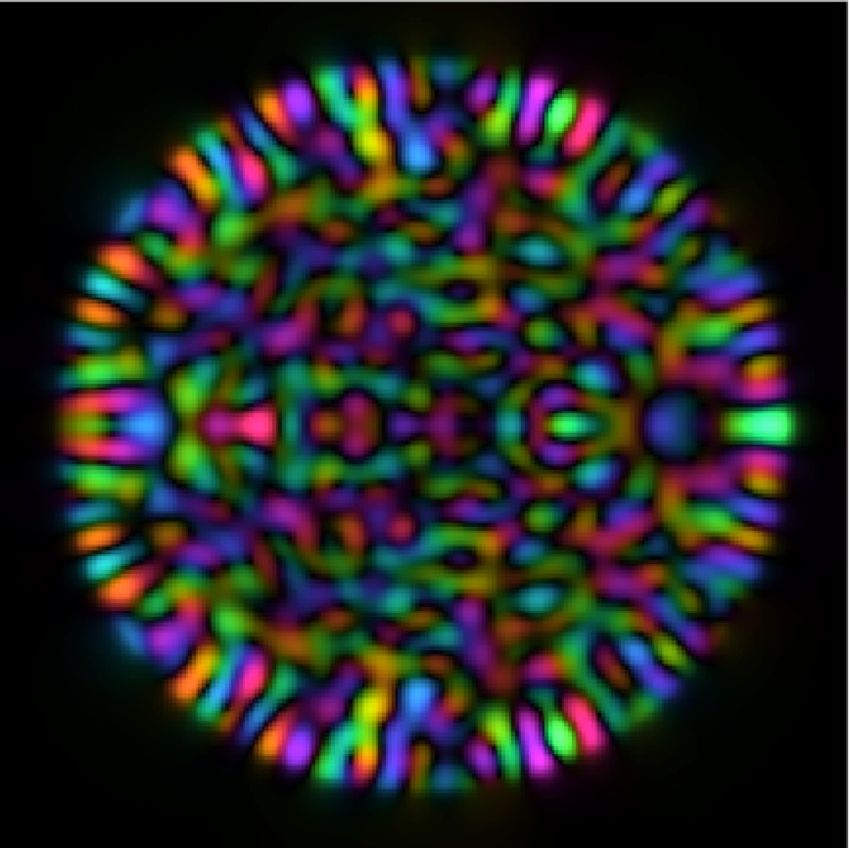
7

                                                Beam block
                                                                                                          (e)                   (h)
                                                                              Polarisation maintaining
                          HeNe          HW1                   HW3                single mode fibre
                          Laser                                                   (reference arm)
              LED                       PBS1
          illuminator                          HW2 PBS
                                                                SF1
                              QWP1                  2
                        BS3                                      SF2
                                  BS1                                             DMD
                                                     20x Objective lenses
               C3                                                                                         (f)                  (i)
                          C2             Proximal                             QWP2
                                           facet             Distal                              HW4
           Alignment cameras                                 facet
                                         Multimode fibre                                   BS2
                                                                      O                              C1

         (a) Transmission Matrix Measurement System                         High-speed camera

         (b)                             1     (c)                              (d)
                        Amp.                                                                              (g)                   (j)
                               Phase
                               (rad.)

                                         0

FIG. 4: Proof of principle experiments: (a) Experimental set-up to measure the full TM of a MMF, emulate ATM measurement with a
guide-star, and image through the MMF using the full TM and ATM. HW = half wave-plate, QW = quarter wave-plate, BS = beamsplitter,
PBS = polarizing beamsplitter, SF = spatial filter. SI §S3 provides a more detailed description of the set-up. (b) Fully sampled TM of MMF
represented in PIM basis. Inset shows an enlarged region of the TM indicating the fine structure around the main diagonal. A larger version
of this figure is shown in SI §S4. Movie 1 shows the input and output fields used to fully sample the TM, which also visually highlights the
symmetries present in the MMF transform (see SI §S10). (c,d) Power ratio maps of scanned foci using the fully sampled TM (c) and guide-star
based ATM (d). Guide-star location is marked with a red circle. (e-g) Example transmission images of a resolution target obtained with the
fully sampled TM. The location where the resolution target is inserted at the distal facet of the fibre is marked with an O. (h-j) Examples of
transmission images of the same scene as (e-g), in this case obtained with guide-star based ATM. Movie 2 shows the focus being scanned in
2D across the isoplanatic patch at the distal facet of the MMF (see SI §S11).

by T0 = PD0 P† . The ATM can now be used to predict the                                     distributed over its columns – meaning that columns repre-
proximal field modulations required to move the focus both                                  senting points close to the guide-star are well captured, while
azimuthally and radially (see Fig. (1f-g)). Evidently, as will                              the errors in columns representing points further away grow
be shown later, knowledge of the ATM gives more general                                     with distance from the guide-star. This results in an isopla-
control over the output field than simply shifting the position                             natic patch that gradually collapses around the location of the
of a focus.                                                                                 guide-star as pd reduces. Figures (3g-l) show simulations of
                                                                                            the guide-star based imaging performance, indicative of the
   The fidelity of the ATM will clearly depend upon how well                                spatial variation in contrast and resolution in each case. Here
we can estimate the basis in which the TM is diagonal (i.e. the                             imaging across the entire facet appears to be disrupted once
validity of the approximation in Eqn. (3)). Figure (3) shows                                pd falls below ∼25%.
simulations of the imaging performance through a MMF as
our ability to accurately estimate the diagonal basis is com-                                  The angular extent of the tilt–tilt memory effect, α, is
promised. We simulate the measurement of ugs using a guide-                                 related to a single parameter describing the sample: the
star placed at the core-cladding boundary (marked by a red                                  thickness of the scattering layer Ls , so that α ∼ λ/(2πLs ),
circle in Fig. (3)), and construct the ATM. See Methods for a                               where λ is the incident wavelength [13]. This raises the
detailed description of these simulations, which capture how                                question of whether it is also possible to derive a similar
power is spread away from the diagonal of the TM in a re-                                   equation describing the limits of the memory effects in
alistic manner. Figures (3a-f) show the power-ratio pr - the                                MMFs. We start by noting that, as shown in Fig. 3a, an ideal
ratio of power focussed into a target spot using the ATM com-                               perfectly straight MMF supports a rotational memory effect
pared to total power transmitted to the distal facet, as pd , the                           of 2π, and a quasi-radial memory effect of r, regardless of
percentage of power on the main diagonal of the real TM D,                                  its numerical aperture, core diameter or length. However,
decreases. Each panel maps how the power-ratio varies over                                  the size and shape of the isoplanatic patch exhibited by real
the distal facet - capturing the size and shape of the isoplanatic                          MMFs is highly sensitive to a large number of parameters.
patch. We see that the error in the ATM T0 is non-uniformly                                 These include misalignments of the optical system at the
8

input and output of the fibre (at least 6-degrees of freedom        ing the fully sampled TM (4c), and a guide-star based ATM
at each end), the departure of the cross-sectional refractive       (4d). The ATM was constructed from data recorded by a sin-
index profile of the fibre from the ideal (or assumed) case,        gle pixel of the camera imaging the output facet, mimick-
how this profile varies along the fibre’s length, and the bend      ing the action of a guide-star. The extent of the isoplanatic
configuration of the fibre [33]. This renders finding an            patch in Fig. (4d) matches well with Fig. (3f) as predicted.
analytical expression for the extent of the memory effect in        Figures (4e-g) show transmission images of a resolution tar-
MMFs a challenging task. Nevertheless, the combined effect          get using the fully sampled TM. Figures (4h-j) show the same
of these parameters is to spread power into the off-diagonal        scenes imaged using the ATM (more detail of how these im-
elements of the real TM D, and we find that the approximate         ages was recorded is given in Methods). As expected, we
area of the isoplanatic patch, Aiso , is related to the fraction    see that imaging is possible through a small isoplanatic patch
of power remaining on the diagonal of the actual TM, pd ,           around the guide-star, and objects outside this patch are not
according to: Aiso ∼ πr2 pd . See Methods for a derivation          discernible as we are unable to create a high contrast focus in
of this expression and the approximations used. This trend is       these regions. The gradual reduction in resolution and contrast
qualitatively apparent in Fig. (3).                                 away from the guide-star is analogous to the situation found in
                                                                    memory effect based imaging through thin scattering layers.
Proof of principle experiments                                         We note that in these experiments, the object (resolution
In order to test our concept in practice, we design an exper-       target) is positioned ∼ 40 µm away from the distal facet of the
iment capable of measuring the TM of a step index MMF at            fibre. Therefore, in order to reconstruct an image of the ob-
a single circular input and output polarization. We study a         ject in focus, the scanned foci had to be axially refocussed
MMF of NA = 0.22, core diameter = 50 µm, and L ∼30 cm               from the distal facet to the object plane. Due
                                                                                                                  to theqcylindrical
in length, supporting 754 spatial modes per polarisation at

                                                                    symmetry of the fibre, the radial k-vector kr = kx2 + ky2
a wavelength of 633 nm. These dimensions are chosen as a
typical example of a MMF that may find micro-endoscopic             of input light is approximately preserved at the output – which
imaging applications. Since the input circular polarization is      is a consequence of the quasi-diagonal nature of the fibre TM
maintained over propagation through short lengths of fibre,         in the PIM basis. As previously demonstrated in refs. [17, 40],
we sample an orthogonal sub-space of the full TM, which is          refocussing can be achieved by taking advantage of this sym-
sufficient for high-contrast imaging behind the distal end [33].    metry and adding a quadratic ‘lensing’ phase term directly
The experimental set-up is similar to that described in ref. [38]   to the field that is generated by the DMD. We note this in-
and is shown in Fig. (4(a)). The spatial mode of input light is     put transformation is also related to the recently reported
controlled using a digital micro-mirror device (DMD) in the         ‘chromato-axial’ memory effect studied in other forward scat-
Fourier plane of the proximal fibre facet, and the distal fibre     tering media [41]. Therefore we actually create fields corre-
facet is imaged onto a high-speed camera, along with a coher-       sponding to defocussed spots at the distal facet of the fibre,
ent reference beam enabling extraction of the complex field         which then focus onto the resolution target. Despite this in-
via phase stepping holography (See Methods, SI §S3 and §S4          crease in complexity, Figs. (4h-j) demonstrate that this refo-
for more details, and §S9 details the loss throughout the ex-       cussing can be successfully achieved using the ATM, which
perimental system).                                                 affords a high level of control over the field within the isopla-
                                                                    natic patch. SI §S5 shows the refocussing capability in more
   We first fully sample the TM of the MMF at a single polari-
                                                                    detail.
sation. After correcting for coarse misalignments in the input
and output beams following the strategy outlined in ref. [33]          In addition to imaging, it is also possible to project pat-
(we note this does not require an optimisation procedure), and      terns through the MMF into the isoplanatic patch, examples
transforming to the PIM basis representation, the fully sam-        of which are shown in SI §S6. We also studied the effect of
pled TM possesses pd ∼15 % of its power on the main di-             fibre deformation on guide-star assisted focusing, and found
agonal (TM shown in Fig. (4b)). The degree of mode cou-             only a minor reduction in the power-ratio of foci was observed
pling in the TM can also be quantified by the ratio of L/`f ,       when the fibre was bent through 90◦ with a radius of curvature
where `f is the TMFP in the fibre mode (PIM) basis, i.e. the        of ∼10 cm, as shown in SI §S7. This result shows there is po-
estimated length of fibre beyond which the TM can be con-           tential for applying single-ended guide-star based TM calibra-
sidered fully coupled. In this case we find our experimentally      tion to image through flexible MMFs undergoing time varying
measured TM has a level of mode coupling consistent with            deformations. More generally, these refocussing and pattern
L/`f ∼ 0.02, a value we estimate by following the methods           projection results show that point-spread-function engineering
given in ref. [39]. Therefore, in this experiment we antici-        should be possible within the isoplanatic patch [42].
pate a guide-star assisted imaging performance equivalent to           The location of the guide-star on the distal facet also plays
that predicted in Fig. (3f) - i.e. an isoplanatic patch extending   a key role in determining the accuracy of the ATM, and thus
around the guide-star, but not reaching across the entire output    the size and shape of the isoplanatic patch. Each focus is
facet of the fibre.                                                 formed as a superposition of PIMs which interfere construc-
   Figures (4c,d) show the experimentally measured power ra-        tively. We can only measure the phase change of PIMs that
tio maps of foci generated at the distal facet of the fibre us-     have an intensity profile that overlaps with the guide-star posi-
9

                                                                                             17
tion. Therefore, it is preferable to choose a guide-star location                                 (a)
that overlaps with the highest number of PIMs. Inspecting                                                                                    0                                                                                                                                                                                                                                                                                                                                                                                                                                                                                                                                1

the rows of matrix P, which hold this overlap information,
reveals that guide-star locations at the core-cladding bound-                                0

                                                                      PIM radial index (p)
                                                                                             17
ary overlap with all of the PIMs - although we note that some                                     (b)
PIMs of index ` = 0 will have very low intensity at the edge
of the core as their fields are concentrated mainly on the fibre
axis. Therefore we have chosen a guide-star positioned at the                                0
                                                                                             17
core-cladding boundary.                                                                           (c)
   It is straight forward to test alternative guide-star positions
in our proof-of-principle experiments - moving the guide-star
                                                                                             0
simply means choosing a different camera pixel to use for                                        -48    -24               0                  24                                                                                                                                                                                                                                                                                                                                                                                                                                                                                                                               48
ATM construction. Figure (5) shows the experimental power                                               PIM azimuthal index (vortex charge `)    AAAB63icbVBNS8NAEJ34WetX1aOXxSJ4KkkV9Fj04rGC/YA2lM120i7d3YTdjVBC/4IXD4p49Q9589+YtDlo64OBx3szzMwLYsGNdd1vZ219Y3Nru7RT3t3bPzisHB23TZRohi0WiUh3A2pQcIUty63AbqyRykBgJ5jc5X7nCbXhkXq00xh9SUeKh5xRm0t9FGJQqbo1dw6ySryCVKFAc1D56g8jlkhUlglqTM9zY+unVFvOBM7K/cRgTNmEjrCXUUUlGj+d3zoj55kyJGGks1KWzNXfEymVxkxlkHVKasdm2cvF/7xeYsMbP+UqTiwqtlgUJoLYiOSPkyHXyKyYZoQyzbNbCRtTTZnN4ilnIXjLL6+Sdr3mXdbqD1fVxm0RRwlO4QwuwINraMA9NKEFDMbwDK/w5kjnxXl3Phata04xcwJ/4Hz+AA60jj8=

ratio maps for three different choices of guide-star location,                        1           (d)           (e)                    (f)
along with the theoretical level of overlap with the PIMs in
each case. As expected, the area of the isoplanatic patch is
maximised when the guide-star is placed on the core-cladding
boundary (Fig. (5a)), enabling recovery of most of the diago-
nal elements of the ATM in the PIM basis. As the guide-star                           0
location is moved radially inwards towards the centre of the
core, the number of PIMs sampled by the guide-star progres-
sively decreases (Figs. (5a-c)). When the guide-star is placed       FIG. 5: Choice of guide-star location: (a-c) Theoretical abso-
                                                                     lute values of the level of overlap of all PIMs with three different
at a radius of a/2, we observe a strong arc in the isoplanatic
                                                                     guide-star locations. Maps (a,b,c) corresponds to guide-star loca-
patch, a signature of the rotational memory effect (Fig. (5e)).      tions shown by red circles in (d,e,f). The colour of point `, p in PIM
This isoplanatic arc is formed as projection of foci to the same     maps represents the relative level of overlap of ψ`,p with the speci-
radius as the guide-star require the same combination of PIMs,       fied guide-star location. (d-f) Experimentally measured power ratio
the phase delays of which have been accurately sampled in            maps using ATMs reconstructed from guide-stars in the three differ-
the ATM. However we also observe a sharp reduction in the            ent locations, marked with red circles. A guide-star positioned at the
power-ratio when the focus is moved radially in Fig. (5e) as         core-cladding interface gives the greatest level of overlap with all of
                                                                     the PIMs and therefore the largest isoplanatic patch. A guide-star po-
these points require the constructive interference of different
                                                                     sitioned on the fibre axis achieves the lowest level of overlap with the
combinations of PIMs, some of which are not well-sampled             PIMs, and the isoplanatic patch shrinks to a single diffraction limited
by the guide-star. When the guide-star is located on the fi-         point in this case.
bre axis, it exclusively samples only the PIMs with a vortex
charge of ` = 0 (Fig. (5c)), and the isoplanatic patch contracts
to a single spot as shown in Fig. (5f).
   There is one point on the distal facet that we know how to        that we plan to investigate in more detail in the future.
focus on perfectly: the position of the guide-star itself, which
has been directly measured. However, as can be seen in both             Equation 7 stipulates that we must know the location of
simulations and experiments in Figs. (3-5), as pd decreases,         the guide-star on the distal facet in order to apply the phase
then using the ATM does not yield a perfect focus even onto          correction term σ. However, if the location of the guide-star
the guide-star itself. This is a consequence of our assumptions      is unknown and σ is omitted (i.e. σ = 0), D0 still provides an
that the fibre TM is perfectly diagonal and unitary - assump-        estimate of the TM of the MMF, but with an unknown rotation
tions that become less accurate with lower values of pd . To         between the proximal and distal planes. We note that in this
mitigate this, when scanning over the guide-star location, the       case, the approximate radial location of a guide-star at an
proximal field returned by the ATM can be replaced with ugs .        unknown position can be retrieved, as it is uniquely encoded
Points at the same radius as the guide-star may also be created      in the relative amplitudes of the PIMs overlapping with the
with a higher power ratio than achievable with the ATM, by           guide-star, which is extracted by decomposing ugs in the PIM
rotating the field used to generate the guide-star focus around      basis. This implies that the methods presented here may be
the fibre axis - i.e. directly employing the rotational memory       possible even without specifically engineering a guide-star on
effect [35]. This observation also points to a more sophisti-        the distal facet of the fibre. For example, a guide-star may
cated approach to reconstruct the ATM: instead of forcing D0         be formed at a random location by optimising a non-linear
to be diagonal, we could try to iteratively search for a non-        feedback signal at the proximal end of the fibre [44]. Once
diagonal and potentially non-unitary D0 , allowing the min-          the proximal field required to generate a focus, ugs , is found,
imum power in off-diagonal elements [43], so that PD0 P†             the focus can then be scanned in 2D using the methods we
also perfectly focusses onto the guide-star when operating on        have presented here.
input field ugs . This is a severely under-constrained problem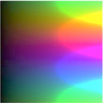
10

                         DISCUSSION                                  they have yet to be experimentally realised in MMFs of high
                                                                     enough resolution to be useful for imaging. The re-imaging
                                                                     properties of graded index fibres have also been demonstrated
   In summary, we have demonstrated the possibility of guide-
                                                                     to enable a spot to be focussed at a chosen location within
star assisted imaging through multimode fibres, which can be
                                                                     up to half of a distal facet using a non-linear feedback sig-
calibrated with access only to the proximal end of the fibre.
                                                                     nal from two-photon fluorescence [54]. However, in this case,
We believe this technique to hold promise for the develop-
                                                                     an optimisation process taking on the order of several min-
ment of flexible multimode fibre based imaging systems. The
                                                                     utes was required to achieve a focus at each new location.
reconstruction of the ATM, and of the images through the fi-
                                                                     The guide-star assisted imaging concept we present here is ar-
bre, requires no iterative phase retrieval, and invokes no as-
                                                                     guably simpler than these recent proposals, although it may be
sumptions about the statistical properties of the scene at the
                                                                     more limited in terms of the accuracy of the forward TM that
end of the fibre - instead relying on assumptions about the
                                                                     can be recovered, and the length of the fibre that may be cal-
properties of the fibre itself. Using a high-speed DMD ca-
                                                                     ibrated. In addition to spatial correlations in weakly coupled
pable of modulating input light at ∼20 kHz, measurement of
                                                                     MMFs, we also note that spatio-temporal correlations have
the proximal field that focuses on a fluorescent guide-star, ugs
                                                                     been identified in MMFs with strong mode coupling that may
(from which the ATM is calculated) consisting of, for exam-
                                                                     prove useful for pulse delivery [55, 56]. Ultimately, we hope
ple, ∼1000 modes can be performed in ∼200 ms using phase
                                                                     that some combination of our imaging strategy, in conjunction
stepping holography [38, 45]. Using a highly reflective guide-
                                                                     with the alternative concepts above, may provide the most ro-
star, the same calibration could potentially be achieved in a
                                                                     bust method to enable imaging through flexible MMFs.
single shot - albeit with lower SNR [2, 23] (SI §S8 contrasts
                                                                        Beyond applications to step index optical fibres, and in
these two methods). Therefore there is potential for both cali-
                                                                     answer to our questions posed earlier, we have shown that
bration and imaging to be performed in real-time.
                                                                     guide-star assisted imaging need not invoke tilt or shift
   In our proof of principle experiments, the isoplanatic patch      memory effects, and can be extended to any scattering system
does not extend over the full area of the distal facet. How-         in which we have an estimate of the basis in which the TM
ever our simulations show that the area of this isoplanatic          is quasi-diagonal. Prior knowledge of this sort can be under-
patch can be significantly increased by making a better esti-        stood as a generalisation of the concept of the TMFP to spaces
mate of the basis in which the TM of the MMF is diagonal             other than the momentum basis [39]. i.e. advance knowledge
(see Fig. (3)). Such an estimate can be achieved by opti-            that a scattering system possesses an optical path length
mising the fibre parameters with access to the full TM, be-          that is much lower than a ‘generalised’ TMFP in a known
fore subsequent deployment of the system as a flexible micro-        (arbitrary) basis. The diagonal nature of the TM indicates that
endoscope [33, 46], which will be a focus of our efforts in          spatial modes input in the diagonal basis are not randomised
future work. To image through longer MMFs which possess              into the entire vector space describing the allowed modes
higher levels of mode coupling (and therefore lower values of        within the structure. Our work provides a guide on how to
pd even after fibre parameter optimisation), we envisage that        efficiently hunt for and make use of memory effects in optical
multiple guide-stars, distinguished by, for example, emission        systems of arbitrary geometry. This concept may be applied
frequency or speckle pattern contrast [47, 48], could be used        to a range of other media including graded-index [57, 58] and
to increase the total area of the distal facet through which it      photonic crystal fibres [59], few-mode fibre bundles (which
is possible to image. If necessary, accurate guide-star place-       have the constraint that the guide-star is ideally placed in the
ment could potentially be achieved using, for example, laser-        far-field of the output [60]), photonic lanterns [61], opaque
ablation-assisted attachment of fluorescent sensors [49].            walls (i.e. imaging around corners) [62], and artificially
    We highlight that recently there have been several innova-       engineered photonic networks and scattering systems.
tive proposals to achieve single ended TM characterisation of
a MMF. For example, Gu et al. proposed recovery of the for-
ward TM by measurement of the round trip reflection matrix
of a fibre in which the distal facet has been engineered with a                                METHODS
partial reflector of spatially varying reflection coefficient, and
moveable shutter [50]. The same group more recently sug-             Construction of matrix P
gested a simpler approach with a uniform partial reflector that      To perform guide-star assisted imaging through MMFs, we
can go some way to improving spot formation [51]. Gordon             must estimate matrix P, that transforms from the propagation
et al. proposed the placement of a stack of patterned spectral       invariant mode (PIM) basis to real-space. The PIMs are found
filters at the distal facet and recovering the forward TM by         by solving the wave equation in a cylindrical geometry. This
measuring the reflection matrix at multiple frequencies [52].        reduces to finding the roots of the scalar characteristic equa-
Chen et al. proposed placing a compact spatial multiplexer at        tions describing the modal dispersion [32].
the distal facet capable of imprinting a mode dependent time
delay or frequency modulation [53]. The engineering require-                             J`−1 (u)    K`−1 (ω)
                                                                                     u            +ω          = 0,              (10)
ments of these proposals are technically challenging, and so                              J` (u)      K` (ω)
11
where J` is a Bessel function of the first kind of order `, and the tilt of the input light can be found by performing the
K` is a modified Bessel function of the second kind of order equivalent to (i) and (ii), but summing over the rows rather
`. u and ω are normalised transverse wave-numbers which are than the columns of the TM. Once these misalignments are
related to the fibre parameters through found, they can be represented as misalignment matrices
1 at the proximal end (Rpr ) and at the distal end (Rdl ), as
u = a k 2 n2core − β 2 2 , (11) described in more detail in SI §S4.
1
ω = a β 2 − k 2 n2core 2 ,
(12)
Simulations
ω 2 = v 2 − u2 , (13) The optical transformation properties of fibres in real-space
v = akNA, (14) are modelled following the methods in ref. [33], by decom-
2 posing real space input fields into the PIMs, multiplying by a
NA = n2core − n2clad . (15)
TM represented in the PIM7→PIM basis (D), and transform-
Here a is the radius of the core, NA is the numerical aper- ing back to real space (see Fig. (1a)): T = PDP† .
ture of the fibre and ncore and nclad are the refractive indices An ideal fibre (as simulated in Figs. (1) and (2)), of length
of the core and cladding respectively. In this work we use L is modelled by a diagonal matrix D, where the nth diago-
the manufacturer’s values of a = 25 µm and NA=0.22. k is nal element is given by eiLβn . To model non-ideal fibres with
the vacuum wavenumber: k = 2π/λ, where λ is the vac- quasi-diagonal TMs in the PIM basis, as shown in Fig. (3),
uum wavelength. β is the propagation constant describing the simulated misalignment matrices R are introduced that trans-
phase velocity of each mode. Eqn. 10 may have multiple roots form the real-space field at each end of the fibre into a new
u`,p , indexed by the vortex charge ` specified in the order of real-space basis that is laterally (dx and dy) and axially (dz)
the Bessel functions, and radial index p which counts the roots shifted, and tilted (about x and y), and defocussed a small
for a particular choice of `. Once the roots have been found, randomly chosen amount. A quasi-diagonal Dq with realistic
the function ψ`,p (r, θ) represents the complex 2D field profile off-diagonal coupling is created by absorbing these misalign-
of the mode indexed by `, p according to Eqn. 4. Here ω`,p ment matrices into the TM in the PIM7→PIM basis, i.e. Dq =
are related to u`,p through Eqn. 13, and r and θ are the radial R0† 0 0 † 0
dl DRpr , where Rpr = P Rpr P and Rdl = P Rdl P are
†
and azimuthal coordinates respectively across the core. Roots the two different misalignment operators at the proximal and
with a real phase velocity β`,p are propagating modes within distal end of the fibre respectively here represented in the PIM
the core. K` takes argument ω`,p , which is imaginary when basis. Therefore to reduce the power on the diagonal (pd ) of
β`,p < k 2 n2core . This then describes the evanescent field in the Dq , and spread it off the diagonal in a realistic manner, the
cladding of the fibre (i.e. for the region r ≥ a). The PIMs, in- magnitudes of the randomly chosen misalignment in each di-
dexed by `, p are ordered into a 1D list, indexed by n. Once the mension are increased.
2D complex functions describing each PIM have been found, Figure (3) shows modelling of the reconstruction of the
column n of matrix P is constructed by representing the com- ATM, and the performance of using it to focus and image
plex field of the nth PIM in Cartesian coordinates on a 2D through the fibre pd is decreased. To simulate this, we use
grid, and reshaping it into a column vector. T = PDq P† to calculate the field required to focus on the
To account for some of the experimental misalignments, guide-star, ugs , where ugs = T† vm0 , and column vector
misalignment operators are measured and applied at each end vm0 represents the desired field in vectorised form (i.e. zeros
of the fibre that remove course position and tilt misalignments everywhere except for 1 at the element m0 corresponding to
of the input and output. These operators are found following the location of the guide-star). ugs is then used to reconstruct
the coarse alignment methods in ref. [33]. In brief, we make the ATM T0 according to Eqns. (7-9). The ATM T0 is then
use of the fact that both ends of MMF are accessible before it used to calculate the estimated input fields required to raster
is employed as an endoscope, and measure the full real-space scan a focus across the distal facet of the fibre, which are then
TM of the fibre (at a single polarisation). This real space TM propagated through the real TM T, enabling the power ratio
can be processed without optimisation to reveal estimates of maps and reconstructed images to be modelled.
the position and tilt misalignments of the inputs and outputs
in the following ways: (i) The central position of the core at Binary amplitude hologram design
output can be found by measuring the centre-of-mass of the A DMD is used to shape the light into the MMF dur-
sum of the intensity of all output measurements. (ii) The tilt ing TM measurement and for imaging. To generate an ar-
of the output can be found by measuring the centre-of-mass of bitrary (bandwidth limited) spatially varying complex field
the sum of the intensity of the Fourier transform of all output A = A(x, y)eiα(x,y) in the first diffraction order in the Fourier
measurements. Both of these methods can be understood as plane of the DMD (x and y being Cartesian coordinates of
operations involving summing over the absolute square of real-space in the optical Fourier plane of the DMD), we en-
the columns of the measured TM. Under the assumption that code the inverse Fourier transform of A, i.e. B = F −1 (A) =
0 0
the TM is unitary, the transpose of this TM is equivalent to B(x0 , y 0 )eiγ(x ,y ) , into a binary amplitude hologram to be
the TM if it were measured in the opposite direction through displayed on the DMD, H(x0 , y 0 ). Here x0 and y 0 are Carte-
the fibre. Therefore the position of the core at the input, and sian coordinates on the DMD chip. Following [63, 64],You can also read