Micro Torque MT5000 - OPERATING INSTRUCTION MANUAL - Surgical Drill System
←
→
Page content transcription
If your browser does not render page correctly, please read the page content below
Micro Torque MT5000
    Surgical Drill System

     OPERATING
    INSTRUCTION
      MANUAL

      Surgical Instruments of Excellence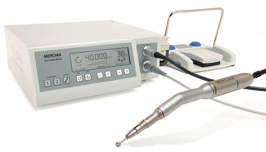
Micro Torque MT5000                                                            Surgical Instruments of Excellence

PRODUCT RANGE
For more than 50 years Mercian has been committed to supplying high quality surgical Instruments
for the UK Hospitals, our motto is ‘Surgical Instruments of Excellence’ - our product range includes:

     •    Spinal Instruments
     •    Hand Surgery Instruments
     •    Micro Surgery Instruments
     •    Cardiac and Vascular Instruments
     •    Endoscopic Instruments
     •    Easy Cut Scissors
     •    Motor Line Products
     •    Surgeons Operating Chairs
     •    Shoulder Instruments

SERVICE CONTACT NUMBERS
We have an experienced sales team who can discuss our product range and offer advice and sup-
port. Please contact us at:

     Mercian Surgical Supply Co Ltd.,
     10, Topaz Business Park,
     Topaz Way,
     Bromsgrove,
     Worcestershire,
     B61 0GD,
     UK.

     Tel:		    +44 (0) 844 879 1133
     Fax:		    +44 (0) 844 879 1155
     Email:    info@merciansurgical.com
     Web:      www.merciansurgical.com

Accreditations: ISO 13485:2016 | Directive 93/42/EEC | MDR 2017/745

                                                                                     Revision 3 - May 2021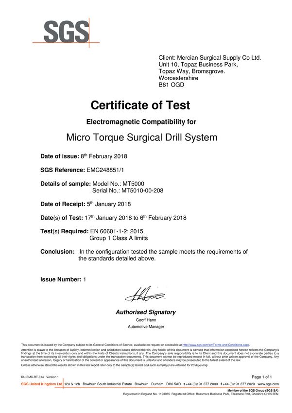
Micro Torque MT5000                                                                                                            Surgical Instruments of Excellence

CONTENTS
					                                                                                                                                                      PAGE
SAFETY PRECAUTIONS........................................................................................................................................2
1   INTRODUCTION.............................................................................................................................................3
    1.1 Operating Conditions.............................................................................................................................3
    1.2 Intended Use............................................................................................................................................4
2   COMPONENTS...............................................................................................................................................4
3   PREPARING FOR USE..................................................................................................................................5
4   INSTALLING THE STERILE IRRIGATION TUBING IN TO THE PUMP UNIT ...................................
    ON THE CONSOLE........................................................................................................................................7
5   CONTROL UNIT FUNCTION AND DISPLAY...........................................................................................8
6   USING THE CONSOLE UNIT FUNCTIONS.............................................................................................9
    6.1		 Using and Setting the ‘Pre Set’ Function........................................................................................9
    6.2		 Adjusting the Speed of the ‘Micro Motor’.....................................................................................10
    6.3		 Setting the Irrigation Functions on the Display............................................................................11
    6.4		 Forward and Reverse Settings on the Display.............................................................................12
    6.5		 Set up Menu function........................................................................................................................13
7   FUNCTIONS AND OPERATION OF THE FOOT CONTROL.............................................................15
8   REPLACING FUSES ON THE UNIT.........................................................................................................16
9   SERVICE AND REPAIRS............................................................................................................................16
10 DISCONNECTING THE ‘MICRO MOTOR’ FROM THE HANDPIECE.............................................17
11 LUBRICATION, DISINFECTION AND CLEANING...............................................................................17
    11.1		 Console Unit........................................................................................................................................17
    11.2		 Foot Control.........................................................................................................................................17
    11.3		 Maintenance Procedure ‘Micro Motor’ and Handpieces..........................................................17
12 TECHNICAL DATA....................................................................................................................................... 20
    12.1		 Control Unit......................................................................................................................................... 20
    12.2		 Foot Control........................................................................................................................................ 20
    12.3		 ‘Micro Motor’....................................................................................................................................... 20
    12.4		 Motor Cable........................................................................................................................................ 20
13 TROUBLE SHOOTING................................................................................................................................21
14 GUARANTEE CONDITIONS..................................................................................................................... 22
15 INFORMATION LABEL............................................................................................................................... 23

APPENDIX 1
    EMC Information
			 Special instructions regarding electromagnetic compatibility
			 Electromagnetic instructions
			 Electromagnetic immunity

APPENDIX 2
    EMC and Safety Certificates

Revision 3 - May 2021                                                                                                                                    Page 1
Micro Torque MT5000                                                          Surgical Instruments of Excellence

SAFETY PRECAUTIONS
•    READ this manual and familiarise yourself fully with this equipment before use.
•    The unit must be at REST when attaching or replacing cutting burs.
•    NEVER touch the cutting bur when ‘Micro Motor’ is in motion.
•    Handpieces must only be fitted or replaced when ‘Micro Motor’ is NOT running.
•    DO NOT allow any modifications on the Micro Torque System.
•    If the ‘Micro Motor’ emits an unusual noise during operation STOP using immediately.
•    Pay particular attention to the operating temperature of the Handpiece if the over heating is
     suspected STOP using immediately as this can be hazardous to the patient.
•    Only use COMPATIBLE Handpieces on the ‘Micro Motor’ complying to DIN13940/ISO 3964.
•    Should only be used by staff with the required knowledge and training for surgical procedures.
•    To avoid the risk of electric shock this equipment must be connected to a mains supply with a
     protective earth.
•    Risks of reciprocal interference posed by medical equipment during specific investigations or
     treatments.
•    To safely terminate use of unit - switch off with mains switch on rear of unit.
•    Do not touch the front contacts and the patient at the same time.
•    There are no potential hazards when disposing of this equipment other than when disposing
     of any electronic equipment.

     Environmental exclusions;
•    This equipment is only to be used in a professional healthcare environment.
•    Portable RF communications equipment (including peripherals such as antenna cables
     and external antennas) should be used no closer than 30cm/12” to any part of the MT5000
     including cables specified by the manufacturer. Otherwise, degradation of the performance of
     this equipment could result.

     NOTE: The EMISSIONS characteristics of this equipment make it suitable for use in industrial
     areas and hospitals (CISPR 11 class A). If it is used in a residential environment (for which
     CISPR 11 class B is normally required) this equipment might not offer adequate protection to
     radio-frequency communication services. The user might need to take mitigation measures,
     such as relocating or re-orienting the equipment.

Page 2                                                                             Revision 3 - May 2021
Micro Torque MT5000 Surgical Instruments of Excellence
1 INTRODUCTION
The MT5000 system provides highly efficient and reliable operation and is manufactured to
the highest quality standards. The high performance self ventilating brushless DC ‘Micro
Motor’ drives precision surgical Handpieces at the optimum speed for the procedure being
undertaken.
The ‘Micro Motor’ speed is set on the easy to use Control Console in increments up to a
maximum speed of 40,000 rpm. Forward and reverse operation of the ‘Micro Motor’ is also
selectable on the Console.
The Control Console drives a peristaltic irrigation pump. The pump delivers a sterile water
flow through an external sterile tubing direct to the cutting bur. Simple to operate controls for
setting pump flow rate in increments up to 100% are provided on the Console.
The Control Console has 2 selectable ‘Programmes’ and a dedicated ‘Set up’ function button.
There is also a memory feature that stores the last setting before the machine is switched off
and recalls these final settings when switched back on again.
The ‘Micro Motor’ is operated by the Foot Control. Depressing the central pedal controls the
‘Micro Motor’ speed (up to the maximum figure set on the Console). There are two switches;
one selects forward and reverse operation of the ‘Micro Motor’ and the other toggles the
irrigation pump ON and OFF.
The maximum delivery of torque is delivered in the highest speed range. The highest torque
can be obtained by running the ‘Micro Motor’ at the highest speed when fitted with compatible
Handpiece attachments that have integral reduction gears. This combination will reduce the
operating speed of the instrument but maintain the optimal torque.
The ‘Micro Motor’ and Cable are designed to be sterilised in an autoclave at 134°C. See page
17 for details of Lubrication, Disinfection and Cleaning procedures.
Refer to the relevant sections of these operating instructions for detailed operating information.
A technical specification is provided on page 20 of these instructions.
1.1 Operating Conditions
• Room Temperature: 10 to 25°C / 50 to 77°F
• Relative Air Humidity: 50 to 70%
• Relative Air Pressure: 900 to 1200 hPa
• Storage and Transport -10 to 40ºC / 14 to 104ºF
Conditions
Revision 3 - May 2021 Page 3Micro Torque MT5000 Surgical Instruments of Excellence
1.2 Intended Use
The intra coupling used on the Micro Torque MT5000 motor system is designed for use with
hand held surgical Handpiece attachments that comply with DIN 13940/ISO 3964. Different
attachments are available depending on the application. Some typical procedures and
applications are shown below;
• Sectioning Teeth
• Drilling and Polishing Bone or Enamel
• Sawing Bone
• Trephining Bone
2 COMPONENTS
7
ITEM CODE DESCRIPTION ITEM CODE DESCRIPTION
1 MT5010-00 Electronic Console Unit 5 MT5012-00 ‘Micro Motor’ and Cable
2 MT5018-00 Irrigation Pump Unit 6 MT1124-00 Surgical Handpiece
3 MT5015-00 Irrigation Support 7 MT5243-00 Irrigation Tubing
4 MT5011-00 Footswitch Control
NOTE: For a full list of accessories used with the system, refer to the Mercian Micro Torque
and Bur brochure.
Page 4 Revision 3 - May 2021Micro Torque MT5000 Surgical Instruments of Excellence
3 PREPARING FOR USE
1. Connect the mains power supply cable to the socket at rear of the Console.
2. Locate the irrigation bag support in the hole at back of the Console. Position the upright to suit
and secure with the thumb wheel.
3. Insert the ‘Micro Motor’ connector into the Console.
4. Insert the Foot Control connector into the Console.
NOTE: Take care when locating the connectors in the Console. The connectors are
industry standard ‘Lemo’ plugs and will only fit in one position. Orientate the
connector so that it locates in the socket and push in (when fitted correctly the
connector will click and lock in position). The connector has a spring loaded
sleeve, the initial outward pressure applied when removing the connector will
release the locking mechanism.
Revision 3 - May 2021 Page 5Micro Torque MT5000 Surgical Instruments of Excellence
5. Attach a compatible Handpiece in to ‘Micro Motor’ and make sure that it is fitted securely.
6. Place a Sterile Bur in to the Handpiece and turn the collar anti-clockwise until you feel the
‘click’ of the chuck to secure the bur.
7. Switch ON the Console at the switch at the rear of the unit.
WARNING: Always handle with care when the Console is switched ON and prepared for
use. Inadvertent operation of the foot pedal can cause personal injury to the
user or other persons nearby.
WARNING: Make sure that you feel the ‘click’ of the chuck closing onto the bur to
ensure the locking mechanism is fully closed. There is a danger of the
Handpiece overheating if it is run with the chuck not completely closed. This
can result in lip burn to the patient.
Page 6 Revision 3 - May 2021Micro Torque MT5000 Surgical Instruments of Excellence
4 INSTALLING THE STERILE IRRIGATION TUBING IN TO THE PUMP
UNIT ON THE CONSOLE
1. Hang the bag of sterile water on the upright. (Sterile water is recommeded for use rather than
saline)
2. Insert the spike of the sterile irrigation tubing into the sterile water bottle.
NOTE: Only use original Mercian irrigation sterile tubing.
3. Open the pump lid.
4. Place the larger bore irrigation tubing centrally on the pump rollers and close the lid on to the
tubing.
NOTE: The action of closing the pump lid will centralise and clamp the tube on the rollers.
The pump is designed for use with 3.2mm bore tube and requires no adjustment by
the user.
5. Secure the micro bore irrigation tubing at convenient intervals to the ‘Micro Motor’ cable with
the tubing clips and finally attach to the spray nozzle tube on the Handpiece.
Read instructions before use Do not put fingers in rollers!
Revision 3 - May 2021 Page 7Micro Torque MT5000 Surgical Instruments of Excellence
5 CONTROL UNIT FUNCTION AND DISPLAY
1. Buttons to select the ‘Pre-Set’ program settings 1 and 2.
2. Button to enter the ‘Set up’ menu.
3. Buttons to select FORWARD or REVERSE operation of the ‘Micro Motor’.
4. Buttons to INCREASE (+) and DECREASE (-) the speed of the ‘Micro Motor’.
5. Buttons to INCREASE (+) and DECREASE (-) the pump speed to control the water irrigation
flow rate.
6. ‘Pre-Set’ program selected indicator (P1 or P2).
7. ‘Micro Motor’ operation FORWARD or REVERSE indicator.
8. ‘Micro Motor’ speed display in rpm (revolutions per minute). Shows the set maximum or the
actual operating speed when the ‘Micro Motor’ is in use. (The accuracy is +/- 5%)
9. Bar display indicating the actual operating speed relative to the maximum speed set when the
‘Micro Motor’ is in use.
10. Irrigation flow rate display as a % of the maximum.
11. Socket for Foot Control connector.
12. Socket for ‘Micro Motor’ connector.
Page 8 Revision 3 - May 2021Micro Torque MT5000 Surgical Instruments of Excellence
6 USING THE CONSOLE UNIT FUNCTIONS
6.1 Using and Setting the ‘Pre Set’ Function
Commonly used program settings can be allocated and stored to the 2 quick set up buttons
according to the user’s needs.
The displayed ‘Micro Motor’ maximum speed and pump flow rate will be stored by holding down
one of the 2 program buttons for a few seconds until a beep is heard. The settings will be stored
against that program button and can be retrieved at any time by pressing the relevant button. The
Console will retain these settings until the ‘Pre Set’ button is set again.
Revision 3 - May 2021 Page 9Micro Torque MT5000 Surgical Instruments of Excellence
6.2 Adjusting the Speed of the ‘Micro Motor’
Use the + or - buttons on the Console to set the required maximum speed of the ‘Micro Motor’. The
motor speed (rpm) is ‘stepped’ in increments there are 16 available speeds, these are shown below:
1,000 2,000 3,000 4,000 5,000 6,000 8,000 10,000
12,500 15,000 17,500 20,000 25,000 30,000 35,000 40,000
Figures show rpm (revolutions per minute)
Pressing either the + or - button will move to the next speed in the range - higher or lower as
applicable.
At the end of the speed setting sequence the micro motor will revert to OFF setting.
The Console has an ‘built-in’ memory. When the unit is powered down the last speed setting used
will be recalled when the unit is switched back on again.
NOTE: The Console software will stop the ‘Micro Motor’ instantly the operating pedal on the
Foot Control is released. This is a safety feature of the MT5000 to prevent the bur
from running on.
Page 10 Revision 3 - May 2021Micro Torque MT5000 Surgical Instruments of Excellence
6.3 Setting the Irrigation Functions on the Display
Use the irrigation adjustment + or - buttons on the Console to set the Irrigation flow rate. Again, the
flow rate is adjusted in increments. there are 15 available flow rates these are given as a % of the
maximum pump flow rate. The flow rates available are shown below.
5 10 15 20 25 30 35 40 45 50 60 70 80 90 100
Figures % of maximum flow rate
Pressing either the + or - button will move to the next available flow rate in the range.
At the bottom end of the flow rate sequence the pump will revert to OFF setting.
The Console’s memory will recall the last flow rate setting used when the unit is switched back on
again.
In operation the irrigation function can be toggled between ON (to the set Flow rate) or OFF with the
right hand button on the Foot Control.
NOTE: When the pump is halted by the button on the Foot Control, the pump will cycle back half
a turn before stopping. This is a design feature of the pump that prevents the ‘run-on’ of
the irrigation fluid after the pump is switched off.
Maximum or 100% flow rate delivers 100 ml of water per minute.
When the pump is not operative is indicated on the display.
Revision 3 - May 2021 Page 11Micro Torque MT5000 Surgical Instruments of Excellence
6.4 Forward and Reverse Settings on the Display
The ‘Micro Motor’ rotation can be switched between FORWARD and REVERSE by using the
buttons on the front of the Console. A beep will sound to warn the user when the direction of
rotation has been changed.
The direction of rotation will be shown on the display by the applicable symbol.
Forward Reverse
In operation FORWARD and REVERSE can be selected with the left hand button on the Foot
Control.
This function is NOT stored in the pre-set function or recalled by the memory when the unit is
switched ON. The unit will always display the FORWARD position by default when the unit is
switched ON. The selected position will not change until the opposite direction is selected on the
Console or with the button on the Foot Control.
Page 12 Revision 3 - May 2021Micro Torque MT5000 Surgical Instruments of Excellence
6.5 Set up Menu function
To enter the menu press the set up button to display and then use the + & - buttons to navigate and
select from the following options;
1. Brake options = selected Motor Brake operation from 3 options:
• No brake Will allow the motor to slow down without any braking.
• Soft brake Will allow the motor to brake but without any kick (Default Setting).
• Hard brake Will allow motor will halt the motor immediately.
2. Pump return = selection of the amount of backward rotation of the Pump after motor is
stopped:
• Half Turn Pump reverses half a return after motor stopped.
• Full Turn Pump reverses a full return after motor stopped (Default Setting).
• No return Pump does not reverse when the motor is stopped.
Revision 3 - May 2021 Page 13Micro Torque MT5000 Surgical Instruments of Excellence
3. Motor fault will detect any difference in the currents between the 3 windings in the Micro
Motor. When a Hand Piece or Motor stall occurs there is a difference in the current drawn by
one winding against another, this compares the difference between the current on one
winding against another and if it exceeds the settings selected below it cuts out to protect the
Hand Piece and Motor.
• 1.5 amps Lower setting compares lower level of amps before cutting off.
• 2.0 amps Medium setting compares medium level of amps before cutting off.
• 2.5 amps Higher setting compares maximum level of amps before cutting off (Default
Setting - recommended).
4. Current fault measures the total draw of current when the Motor/Hand Piece is put under
load, therefore as the Surgeon exerts more pressure on the Bur the Motor will require to draw
more current from the board to drive the Motor;
• 4 amps Lower setting.
• 4.5 amps Medium setting.
• 5 amps Higher setting for hard use (Default Setting – recommended).
The maximum recommended current drawn for the Micro Motor is 5 amps; anything
exceeding this during heavy use can cause the Motor to overheat.
To exit the menu screen display press the Set up Menu button.
Page 14 Revision 3 - May 2021Micro Torque MT5000 Surgical Instruments of Excellence
7 FUNCTIONS AND OPERATION OF THE FOOT CONTROL
1. ‘Micro Motor’ speed control pedal 4. Handle for moving pedal around
2. Forward or reverse button 5. Connector for Foot Control into Console
3. Irrigation pump ON/OFF button
WARNING: Always handle with care when the unit is switched ON and prepared for use.
Inadvertent operation of the foot pedal can cause personal injury to the user or
other persons nearby.
Applying gradual pressure to the pedal (1) will increase the ‘Micro Motor’ speed up to the full ‘Pre-
Set’ speed shown on the Console display.
The right hand button (3) on the Foot Control will toggle the irrigation pump between OFF and ON.
FORWARD and REVERSE can be selected with the left hand button (2) on the Foot Control. A beep
will sound to warn the user when the direction of rotation has been changed.
The handle (4) allows the operator to manoeuvre the Foot Control with their foot to suit. The handle
can be positioned raised or lowered as required.
Revision 3 - May 2021 Page 15Micro Torque MT5000 Surgical Instruments of Excellence
8 REPLACING FUSES ON THE UNIT
There are two fuses in the carrier they should be checked and replaced as necessary.
WARNING: Make sure the unit is switched OFF and the power cable is removed from the
MAINS supply before withdrawing the fuses.
NOTE: The fuses are installed in a fuse holder above the power connector located at the rear of
the control unit. The mains cable must be removed from the power socket to access the
tab on the fuse carrier.
To remove the fuse carrier, place the finger nail or a small screwdriver under the tab and pull to
release. Fully withdraw the carrier and rotate downwards to access the fuses.
Replacement 2.5 Amp fuses must be used.
9 SERVICE AND REPAIRS
No servicing or repairs should be undertaken by any agent other than Mercian Surgical
technicians or technicians trained by Mercian Surgical.
Liability cannot be assumed if repairs are undertaken by third parties without authorisation or
the required training.
Page 16 Revision 3 - May 2021Micro Torque MT5000 Surgical Instruments of Excellence
10 DISCONNECTING THE ‘MICRO MOTOR’ FROM THE HANDPIECE
The Handpiece can be pulled apart from the ‘Micro Motor’ easily as shown.
WARNING: Only use COMPATIBLE Handpieces on the ‘Micro Motor’ complying to
DIN13940/ISO 3964.
The Micro Motor and Handpiece are applied parts of the system.
11 LUBRICATION, DISINFECTION AND CLEANING
11.1 Console Unit
The Console unit can we wiped down using a proprietary medical surface disinfection
wipe.
11.2 Foot Control
The Foot Control can be wiped down with a surface disinfectant solution.
11.3 Maintenance Procedure ‘Micro Motor’ and Handpieces
11.3.1 Manual cleaning of Handpieces
Clean and disinfect the exterior of the Handpiece with a clean damp cloth and
suitable disinfection solution.
Note: Products containing acetone, chlorine, and bleach are not recommended
as disinfectants.
Visually inspect the Handpiece and Micro Motor for any remaining debris and
damage.
Note: Handpieces are not suitable for cleaning in an ultrasonic bath.
Indicates that the Micro Motor can be 134˚C Sterilisable in a steam
processed in a washer-disinfector for sterilizer at temperature
thermal disinfection. specified.
Revision 3 - May 2021 Page 17Micro Torque MT5000 Surgical Instruments of Excellence
11.3.2 Automatic cleaning of Handpieces in a washer disinfector
1) Place the Handpieces in the appropriate basket.
2) Pre rinse with cold mains water.
3) Wash with mains water up to 95ºC with alkaline detergent giving a pH of between
8.0 -11.00 in dilution.
4) Rinse with warm mains water at 50°C.
5) Post rinse with warm mains water at 50°C.
6) Final rinse with reverse osmosis water at 90°C.
7) Hot air drying.
Remove the instruments immediately from the Washer/Disinfector and lubricate prior to
sterilisation.
As per HTM 01-01 Part D: Washer Disinfectors.
Caution: Failure to lubricate immediately may lead to internal corrosion of the
instrument and its subsequent failure.
11.3.3 Lubrication of Handpieces and Micro Motor
Always Lubricate before each sterilisation.
Always use Mercian Lubrifluid oil spray order code; 1600064-006.
Procedure for Lubricating Hand Pieces
1) Remove Bur from instrument.
2) Open Chuck up.
3) Hold the Handpiece in a cloth to catch any debris and foreign matter expelled by
the jet.
4) Remove the protective cap from the can, and insert nozzle into the back of the
Handpiece sleeve.
5) Spray for about 1 second.
Note: After lubrication, always stand the Handpiece upright for 5 minutes.
Page 18 Revision 3 - May 2021Micro Torque MT5000 Surgical Instruments of Excellence
Procedure for Lubricating Micro Motor
1) Use the Lubrifluid pointed finer nozzle.
2) Hold the Micro Motor in a cloth.
3) Remove the protective cap from the can, and insert nozzle into the open end of the
Micro Motor.
4) Spray for less than 1 second.
11.3.4 Sterilisation
High temperature steam autoclave at 134 ºC to 137 ºC for 3 minutes.
or
Vacuum autoclave 134 ºC to 137 ºC for 3 minutes.
Drying cycle max 137 ºC for maximum 30 minutes.
As per HTM 01-01 Part C: Steam sterilisation.
Revision 3 - May 2021 Page 19Micro Torque MT5000 Surgical Instruments of Excellence
12 TECHNICAL DATA
12.1 Control Unit
Housing Dimensions 290 x 300 x 110 mm
Weight 5.2 kg
Voltage 100 - 240 V AC
Input Frequency 50 - 60 Hz
Fuses Anti surge, 2.5A
Pump Capacity 100 ml of fluid per minute at 100% flow rate
12.2 Foot Control
Dimensions 201 x 187 mm
Weight 1.8 kg
Cable Length 2.9 m
Anaesthetic Test Class AP
12.3 ‘Micro Motor’
Dimensions Length with coupling 120 mm. Diameter 20 mm.
Weight 120 g
Mechanical Power 45W at 20,000 rpm
Classification IIa
Unloaded Speed 40,000 rpm
Maximum torque 4 Ncm
Noise Level Max 65 dBA
NOTE: The ‘Micro Motor’ is sterilised with the cable connected where applicable.
NOTE: Recommended method of sterilisation is steam sterilisation
134°C / 1bar at an exposure time of at least 15 minutes.
12.4 Motor Cable
Length 2.9 m
Weight 285 g
Classification IIa
NOTE: As above, the recommended method of sterilisation is steam sterilisation
134°C / 1bar at an exposure time of at least 15 minutes
Page 20 Revision 3 - May 2021Micro Torque MT5000 Surgical Instruments of Excellence 13 TROUBLE SHOOTING Condition Cause Action Control unit does not light up. Mains switch off. Switch mains supply ON. No power supply to Console. Check power supply cable. Power supply cable defective. Replace power supply cable. Fuses defective. Fit new fuses. Pump will not run. Pump not engaged. Switch pump ON, on Foot Control switch. Flow rate set at OFF Set desired flow rate. ‘Micro Motor’ not operating. Pump only operates when ‘Micro Motor’ is running. Foot Control is not working. Connector is incorrectly Check connector is correctly inserted into Console. inserted into Console. ‘Micro Motor’ will not operate. Connector is incorrectly Check connector is correctly inserted into Console. inserted into Console. ‘Micro Motor’ connection Check connection between to Cable faulty. cable and ‘Micro Motor’. ‘Micro Motor’ or cable Replace ‘Micro Motor’ or Cable defective. and return to Mercian for repair. ‘Micro Motor’ is ‘over heating’. Prolonged peak load usage. Refer to manufacturer’s instructions. Bearings defective. Stop use and replace ‘Micro Motor’. Handpiece rotates on the Handpiece Chuck Close Handpiece Chuck ‘Micro Motor’. is not closed correctly. Bur in Handpiece rotates Handpiece defective. Replace Handpiece and return intermittently or not at all. to Mercian for repair. Bur not cutting efficiently. Direction of ‘Micro Motor’ Change direction of ‘Micro set in reverse. Motor’. Bur worn and blunt. Change Bur. If the fault cannot be attributed to one of the following causes described above or rectified by one of the specified courses of action the component should be returned to Mercian Surgical for examination and if necessary repair. Repairs should only be carried out by Mercian personnel. Unauthorized repairs or attempted repairs release Mercian from any liability whatsoever. Revision 3 - May 2021 Page 21
Micro Torque MT5000                                                           Surgical Instruments of Excellence

14		GUARANTEE CONDITIONS
		Our products are guaranteed for a period of One Year from the date of delivery of the System.
		Claims under guarantee will only be considered provided the guarantee card has been
		returned to Mercian.
		The Micro Torque Unit will be repaired free of charges if the defects can be attributed to faulty
		material and workmanship. Any other claims particularly for compensation are excluded.
		If any modification or repairs are undertaken by third parties the guarantee will be rendered
		null and void.
		Components should only be replaced ‘like for like’.
		Annual Service is recommended to ensure the safe and reliable operation of the Micro Torque
  System.
     Upon request we will supply oppropriate technical documents to allow service and repair of
     medical equipment to suitably qualified service personel.

Page 22                                                                             Revision 3 - May 2021
Micro Torque MT5000 Surgical Instruments of Excellence
15 INFORMATION LABEL
Serial No
Ref No MT5000
Voltage 100-240V~
Frequency 50-60Hz
Rated Input 40VA
1639 Type B
2016-03
MERCIAN SURGICAL SUPPLY CO LTD
10 Topaz Business Park,
Topaz Way,
Bromsgrove,
B61 0GD,
United Kingdom.
Tel: +44 (0) 844 879 1133
Email: info@merciansurgical.com
Key to Symbols
In conformity with the Council Directive 93/42/EEC
1639 of June 14, 1993 concerning medical devices.
Symbol indicating a Type B Appliance.
A Type B appliance classification is the least
stringent classification and is used for applied parts
that are generally not conductive and can be
immediately released from the patient.
Type B applied parts may be connected to earth.
CAUTION.
Refer to the accompanying documentation.
Symbol indicating the date that the product was
manufactured, expressed as four digits for the year
and two digits for the month.
Symbol confirming the manufacturer’s name and
address.
Revision 3 - May 2021 Page 23Micro Torque MT5000 Surgical Instruments of Excellence
APPENDIX 1
EMC INFORMATION
Revision 3 - May 2021Micro Torque MT5000 Surgical Instruments of Excellence Special Instructions / Notes regarding the MT5000 and Electromagnetic compatibility (EMC) testing to EN60601-1-2:2015+A1:2021 The MT5000 has been tested regarding it’s ability to operate in an environment containing other electrical/electronic equipment (including other medical devices). The purpose of this testing is to ensure the MT5000 is not likely to adversely affect the normal operation of other such equipment and that other such equipment is not likely to adversely affect the normal operation of the MT5000. Despite the testing of the MT5000 that has been undertaken, normal operation of the MT5000 can be affected by other electrical/electronic equipment and portable and mobile RF communications equipment. As the MT5000 is medical equipment, special precautions are needed regarding EMC (electromagnetic compatibility). It is important that the MT5000 is configured and installed/put into service, in accordance with the instructions/guidance provided herein and is used only in the configuration as supplied. The MT5000 has been tested (and should be used only with) the cables and micro motor provided. If the MT5000 is used with cables or a micro motor other than those supplied, this may result in increased emissions or decreased immunity of the MT5000 in relation to EMC performance. It should be noted that neither the cables nor the micro motor provided with the MT5000 should be used on other equipment. To do so may result in increased emissions or decreased immunity of the other equipment in relation to EMC performance. The MT5000 should not be used adjacent to or stacked with other equipment. If adjacent or stacked use with other equipment is necessary, the MT5000 and the other equipment should be observed/ monitored, to verify normal operation in the configuration in which it will be used. The MT5000 essential performance during the emc immunity tests was that in run mode the micro motor speed shall not vary by more than +/-10% and the irrigation pump shall continue to operate, and in standby mode the micro motor or irrigation pump must not unintentionally operate. Revision 3 - May 2021 Appendix 1 - page 1 of 3
Electromagnetic Compatibility Requirements - Emissions

        Required Test                        Compliance                                Comments

RF emissions Group 1                                                      For use in a professional healthcare
			                                                                             facility environment only

          CISPR 11                             Class A

    Harmonic emissions                         Class A

        IEC61000-3-2

    Voltage fluctuations /                    Complied
      flicker emissions

        IEC61000-3-3

                           Electromagnetic Compatibility Requirements - Immunity

 Required Test                    60601 test level for equipment                   Compliance level
		                               used in a professional healthcare
		                                          facility only

   Electrostatic discharge                  ± 8 kV contact                           ± 8 kV contact
            (ESD)                         ± 2, 4, 8, 15 kV air                     ± 2, 4, 8, 15 kV air
        IEC61000-4-2

   Radiated RF EM Fields                      3 V/m                                     3 V/m
       IEC61000-4-3                      80 MHz to 2.7 GHz                         80 MHz to 2.7 GHz

Proximity fields from RF                  385MHz - 27 V/m                          385MHz - 27 V/m
wireless communications           450, 810, 870, 930MHz - 28 V/m           450, 810, 870, 930MHz - 28 V/m
      IEC61000-4-3               1.72, 1.845, 1.97, 2.45GHz - 28 V/m      1.72, 1.845, 1.97, 2.45GHz - 28 V/m
		                                    710, 745, 780MHz - 9 V/m                 710, 745, 780MHz - 9 V/m
		                                   5.24, 5.5, 5.875GHz - 9 V/m              5.24, 5.5, 5.875GHz - 9 V/m

  Electrical fast transient /      ± 2 kV for power supply lines             ± 2 kV for power supply lines
             burst                 ± 1 kV for input / output lines
        IEC61000-4-4

    Surge                           ± 0.5, 1, 2 kV line(s) to earth,         ± 0.5, 1, 2 kV line(s) to earth,
 IEC61000-4-5                   ± 0.5, 1 kV line(s) to line(s) for power ± 0.5, 1 kV line(s) to line(s) for power
		                                            supply lines                             supply lines

		                                ± 2 kV line(s) to earth for input /
		                                           output lines

 Conducted RF                           3 V - 150 kHz to 80 MHz                  3 V - 150 kHz to 80 MHz
 IEC61000-4-6                    6V - ISM bands between 150 kHz to        6V - ISM bands between 150 kHz to
		                                               80 MHz                                   80 MHz

Appendix 1 - page 2 of 3                                                                     Revision 3 - May 2021
Voltage dips, short 0% UT 0% UT
interruptions and voltage (100 % dip in UT) (100 % dip in UT)
variations on power For 0.5 cycle For 0.5 cycle
supply input lines
IEC61000-4-11
0% UT 0% UT
(100 % dip in UT) (100 % dip in UT)
For 1 cycle For 1 cycle
70% UT 70% UT
(30 % dip in UT) (30 % dip in UT)
For 25/30 cycles For 25/30 cycles
0% UT 0% UT
(100 % dip in UT) (100 % dip in UT)
For 250/300 cycles For 250/300 cycles
Power frequency 30A/m N/A
(50/60Hz)
Magnetic field
IEC61000-4-8
Revision 3 - May 2021 Appendix 1 - page 3 of 3Micro Torque MT5000 Surgical Instruments of Excellence
APPENDIX 2
EMC AND SAFETY CERTIFICATES
Revision 3 - May 2021Version: 2.0
EU Declaration of Conformity Date: 10/05/2021
Declaration of Conformity
for Micro Torque Surgical Drill System
European Communities Council Directive 93/42/EEC as amended by 2007/47/EC concerning
Medical Devices as transposed into European national law by the member states.
The undersigned declares that the products described in this document meet the Council Directive
provisions that apply to them and the CE Mark may be affixed.
General Product Name: Micro Torque Surgical Drill System
Mercian Surgical Supply Co Limited, 10 Topaz Business Park, Topaz
Legal Manufacturer:
Way, Bromsgrove, Worcestershire, B61 0GD. UK
Variants: As per Appendix II (This document) – Product Listing/Schedule
Intended Use: Maxillo Facial and Small Bone Surgery
MDD Classification: Class II(a)
Notified Body: SGS Belgium 1639
CE Certificate Reference: GB19/964481
EU Authorised Advena Limited. Tower Business Centre, 2nd Flr., Tower Street,
Representative: Swatar, BKR 4013 Malta.
MDD Conformity EC Declaration of Conformity in accordance with Annex VII of the Medical Device
Assessment Route: Directive coupled with Production Quality Assurance outlined in Annex V
Name John Duffy Position MD
Signed Date 10/05/2021
Who is the natural and legal person with responsibility for the design, manufacture, packaging and labelling before the device
is placed on the market under this manufacturer’s name regardless of whether these operations are carried out by the
manufacturer or on his behalf by a third party.
Page 1 of 2Version: 2.0
EU Declaration of Conformity Date: 10/05/2021
Appendix I – Applicable Standards
This present declaration is also in conformity with the following European standards and Common Specifications:
Standard/Document Name Description
Council Directive concerning medical devices as amended by
93/42/EEC
Directive 2007/47/EC
EN 1041:2008+A1:2013 Information supplied by the manufacturer of medical devices
Medical Devices - Quality Management Systems - Requirements
EN ISO 13485:2016
for Regulatory Purposes
Medical Devices - Application of Risk Management to Medical
EN ISO 14971:2019
Devices
EN ISO 15223-1:2016 Medical devices - Symbols to be used with medical device labels,
labelling and information to be supplied
BS EN 60601-1:2006+A12:2014 Medical electrical equipment - General requirements for basic
safety and essential performance
BS EN 60601-1-2:2015+A1:2021 Medical electrical equipment - General requirements for basic
safety and essential performance. Collateral Standard:
Electromagnetic disturbances. Requirements and tests
Appendix II – Product Listing/Schedule
Part/Catalogue
Description/Name GMDN Code
Number
MT5010-00 Micro Torque Electronic Console 45572
MT5011-00 Footswitch Control 45572
MT5012-00 Micro Motor Complete with Cable 45572
Version History
Version Compiled by Date Description
1.0 John Duffy 18/11/2020 First issue.
2.0 Hayley Claridge 10/05/2021 Revision of ISO 14971:2012 to ISO
14971:2019 and included 60601-1
Page 2 of 2Surgical Instruments of Excellence
Mercian Surgical Supply Co. Limited
10 Topaz Business Park, Topaz Way, Bromsgrove, Worcestershire B61 0GD. UK.
www.merciansurgical.comYou can also read