MIGATRONIC ROBOT SETUP OMRON NJ1500 PLC - ETHERCAT - MIG/MAG - SETUP MANUAL
←
→
Page content transcription
If your browser does not render page correctly, please read the page content below
MIGATRONIC ROBOT SETUP
OMRON NJ1500 PLC – ETHERCAT – MIG/MAG

                               SETUP MANUAL

                        50115039 Valid from 2020 week 19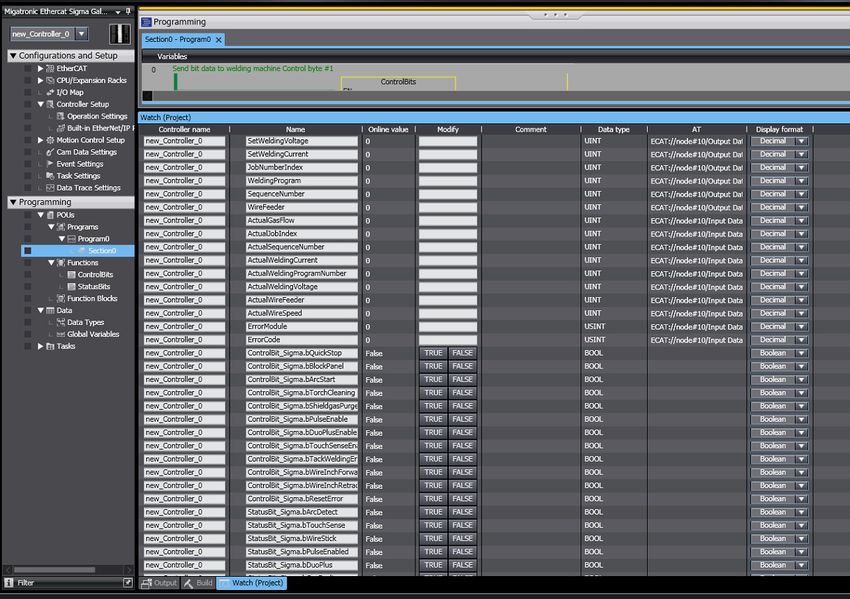
Dansk...................................................................3

    English...............................................................13

2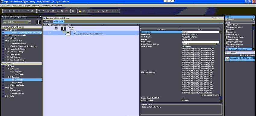
Indholdsfortegnelse

 Introduktion.................................................................................................4

 Klargøring af strømkilden..........................................................................5

 Opsætning af EtherCAT netværket i Sysmac Studio.................................5

 Angiv IP adresse til PLC’en..........................................................................7

 Opret Variabler i Sysmac Studio.................................................................7

 Tilknyt variabler til PDO..............................................................................8

 Opret funktioner til at håndtere PDO på bit niveau.................................9

   ControlBits................................................................................................9

   StatusBits................................................................................................10

 Download til PLC’en, og test funktionalitet...........................................11

                                                                                                                  3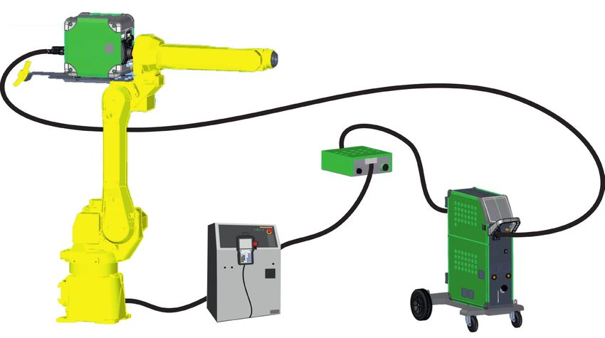
Opsætning af Migatronic MIG/MAG Interface på Omron NJ1500 PLC med EtherCAT

    Introduktion

    For at kunne kommunikere med Migatronics bus interface via EtherCAT skal der anvendes en speciel
    ESI-fil i XML-format til konfigurationen af netværket.
    Standardfilen fra HMS (AnyBus) kan IKKE anvendes.
    Ved programmering af Omron NJ1500 PLC’en anvendes softwaren Sysmac Studio fra Omron.

    I det følgende beskrives kortfattet, hvordan konfigurationen udføres:
    1: Monter EtherCAT modulet fra ANYBUS i Migatronic interfacet.
    2: Monter netværkskablet i PLC’ens EtherCat port (Port 2) og i EtherCAT modulet i interfacet.
    3: Konfigurer Device ID i interfacet ved hjælp af knapperne og displayet på printet. Indlæs CFG-
       filen 10010205 fra SD-kortet. Læs mere om dette i manualen til interfacet.
    4: Opret et nyt projekt i Sysmac Studio fra Omron og opret en EtherCAT netværks-konfiguration
       ved hjælp af dokumentationen til konfigurationsfilen til interfacet.
       Device ID skal være det samme som oprettet under punkt 2.
    5: Opret variabler (UINT, USINT og BOOL) til henholdsvis input og output til kommunikation med
       interfacet.
    6: I I/O Mapping forbindes variablerne til de konfigurerede I/O i EtherCAT setup’en.
    7: Opret funktioner til udmaskning af bit i Control Bytes og Status Bytes.
    8: Download projektet til PLC’en og test kommunikationen.

4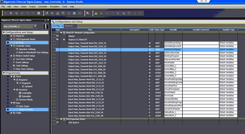
Opsætning af Migatronic MIG/MAG Interface på Omron NJ1500 PLC med EtherCAT

Klargøring af strømkilden

Inden start af opsætning af PLC’en skal strømkilden være monteret med Interface, Wirefeeder og
ANYBUS EtherCAT modul for at kunne kommunikere med strømkilden.
Vælg interface konfigurationsfil 10010205, hvor svejsespænding og svejsestrøm kan styres fra PLC’en.
Indlæs konfigurationsfilen i interfacet. Indtast Device ID på interfacet.
Se manual til RCI² for yderligere information.

 Opsætning af EtherCAT netværket i Sysmac Studio

 Start Sysmac Studio og opret et nyt projekt.
 Installer XML filen fra Migatronics hjemmeside eller fra det medfølgende SD-kort ved at åbne
 EtherCAT folderen og højre-klikke på Masteren.
 Vælg Display ESI Library. Klik på this folder og kopier XML filen fra SD-kortet ind i det åbnede
 vindue.

                                                                                                       5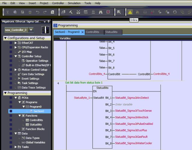
Opsætning af Migatronic MIG/MAG Interface på Omron NJ1500 PLC med EtherCAT

    I værktøjsmenuen findes gruppen Communication Adapters.
    Højre-klik på Anybus CC modulet og vælg Insert.

    Skriv Galaxy under Device Name og skriv 10 i Node Address.
    Node Address skal være det samme som blev indtastet i interfacet i menuen Device ID.

    Klik på Edit PDO Map Settings.
    Indsæt I/O PDO i henholdsvis input- og output-området.
    Hvilke moduler, der indsættes hvor, kan ses i dokumentationen til konfigurationsfilen 10010205.

    Klik på OK for at lukke vinduet igen.

6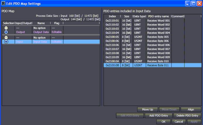
Opsætning af Migatronic MIG/MAG Interface på Omron NJ1500 PLC med EtherCAT
Angiv IP adresse til PLC’en
Klik på Built-in Ethernet/IP Port Settings.
Indtast en IP-adresse og Subnet-adresse til porten, der anvendes til at kommunikere med PLC’en.
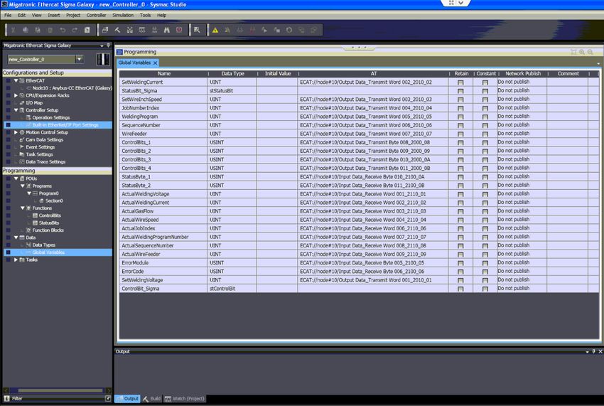
Opret variabler i Sysmac Studio
Klik på Global Variables.
Indtast variabelnavne svarende til dokumentationen for konfigurationsfilen 10010205.
7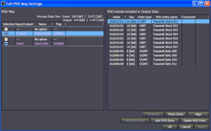
Opsætning af Migatronic MIG/MAG Interface på Omron NJ1500 PLC med EtherCAT

    Tilknyt variabler til PDO
    Klik på I/O Map for at tilknytte variablerne til PDO’erne på EtherCAT netværket.

    I søjlen Variable indtastes navnene på variablerne, der hører til hver PDO.

8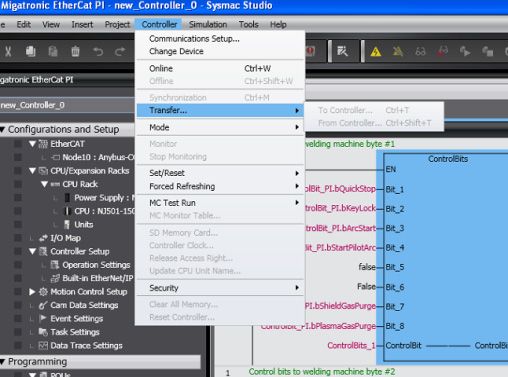
Opsætning af Migatronic MIG/MAG Interface på Omron NJ1500 PLC med EtherCAT

Opret funktioner til at håndtere PDO på bit niveau

Det er ikke muligt at adressere på bit niveau, og PLC’en kan ikke umiddelbart maske byte og integrere
variabler på bit niveau.
Derfor er det nødvendigt at lave en funktion, der kan maske bittene ud af de enkelte byte, så de kan
anvendes til henholdsvis ControlBit og StatusBit til strømkilden.

ControlBits

Funktionen ControlBits er oprettet med 8 bits som input og en Byte som Input/Output.
I ControlBits læses status på de enkelte bits, der er oprettet som globale variabler i programmet.
Start med at nulstille den lokale variabel ControlBit.
Læg herefter værdien af hvert bit til, hvis bittet er ”TRUE”.

Herved opnås at kunne styre de enkelte bits i ControlBit bytene.
En funktion kan kaldes flere steder i programmet; man behøver således kun at lave koden én gang og
kan derefter genbruge blokken.

                                                                                                        9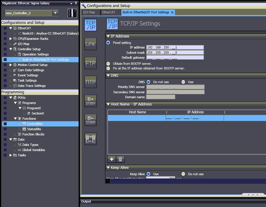
Opsætning af Migatronic MIG/MAG Interface på Omron NJ1500 PLC med EtherCAT

     StatusBits

     Funktionen StatusBits er oprettet med 8 bit som output og en Byte som Input/Output.
     I StatusBits læses status på Byte’n indeholdende status bittene, og herefter skrives de enkelte bit’s
     værdier ud på bit’s, der er oprettet som globale variabler i programmet.
     Inde i funktionen startes med at konvertere fra Unsigned Int til Word format.
     Herefter AND’es hele byte’n med den Hexadecimale værdi, hvormed hvert bit vægtes (dvs.
     henholdsvis 1, 2, 4, 8, 16, 32, 64 og 128 i 10-tal systemet).

     Hvis dette udtryk er ”TRUE”, sætten bittet også ”TRUE”; ellers sættes det ”FALSE”.
     Herved opnås det at maske de enkelte bit ud af status byte’n.
     En funktion kan kaldes flere steder i programmet; man behøver således kun at lave koden én gang
     og kan derefter genbruge blokken.

10
Opsætning af Migatronic MIG/MAG Interface på Omron NJ1500 PLC med EtherCAT
Download til PLC’en og test funktionalitet
Klik på det gule ikon for at gå online på PLC’en.
Klik herefter på ikonet ”to controller” eller brug Controller menuen til at gå online og downloade.
Kontroller at alle led’er i ANYBUS modulet lyser grønt.
Vælg fanen Watch.
Opret de variabler, der ønskes testet, ved at klikke i kolonnen Name og kontroller funktionaliteten.
1112
Contents

 Introduction...............................................................................................14

 Making ready the Power Source..............................................................15

 Setting up EtherCAT Network in Sysmac Studio.....................................15

 Stating IP Address for PLC........................................................................17

 Creating Variables in Sysmac Studio........................................................17

 Connecting Variables to PDO....................................................................18

 Creating Functions for Handling PDO at Bit Level..................................19

   ControlBits..............................................................................................19

   StatusBits................................................................................................19

 Download to PLC and Test of Functionality.............................................20

                                                                                                                  13
Setting up Migatronic MIG/MAG Interface at Omron NJ1500 PLC with EtherCAT
Introduction
To enable communication with Migatronic bus interface via EtherCAT, use a special ESI file in XML
format for configuring the network.
The standard HMS (AnyBus) file can NOT be used.
Use Omron Sysmac Studio software to program the Omron NJ1500 PLC.
Brief description of the configuration procedure:
1: Mount the ANYBUS EtherCAT module in the Migatronic interface.
2: Mount the network cable in EtherCat port (Port 2) of the PLC and in the EtherCAT module in the
interface.
3: Configure Device ID in the interface using PCB buttons and display. Load CFG file 10010205 from
the SD card. Read more in the interface manual.
4: Create a new project in Omron Sysmac Studio and create an EtherCAT network configuration
using the documentation for the configuration file for the interface.
Device ID must be identical to ID created under point 2.
5: Create variables (UINT, USINT and BOOL) for input and output respectively for communication
with the interface.
6: Connect variables in I/O Mapping to the configured I/O in the EtherCAT setup.
7: Create functions for masking bits in Control Bytes and Status Bytes.
8: Download the project to the PLC and test communication.
14Setting up Migatronic MIG/MAG Interface at Omron NJ1500 PLC with EtherCAT
Making ready the Power Source
Prior to setting up the PLC, the power source must be connected to interface, wire feeder and
ANYBUS EtherCAT module to enable communication.
Select interface configuration file 10010205, where welding voltage and welding current are
adjustable at the PLC.
Load the configuration file into the interface. Enter Device ID on the interface.
For more information, please refer to RCI² manual.
Setting up EtherCAT Network in Sysmac Studio
Start Sysmac Studio and create a new project.
Install the XML file from migatronic.com or the included SD card by opening the EtherCAT folder or
right-click on the Master.
Select Display ESI Library. Click on this folder and copy the XML file from the SD card into the
opened window.
15Setting up Migatronic MIG/MAG Interface at Omron NJ1500 PLC with EtherCAT
Find the group of Communication Adapters in the toolbar.
Right-click on the Anybus CC module and select Insert.
Enter Galaxy under Device Name and 10 in Node Address.
Node Address must be identical to the ID entered in the interface in the Device ID menu.
Click on Edit PDO Map Settings.
Insert I/O PDO in input range and output range respectively.
The positions of the modules appear from the documentation for configuration file 10010205.
Click on OK to close the window.
16Setting up Migatronic MIG/MAG Interface at Omron NJ1500 PLC with EtherCAT
Stating IP Address for PLC
Click on Built-in Ethernet/IP Port Settings.
Enter IP address and Subnet address for the port used for communicating with the PLC.
Creating Variables in Sysmac Studio
Click on Global Variables.
Enter Variable names corresponding to the documentation for configuration file 10010205.
17Setting up Migatronic MIG/MAG Interface at Omron NJ1500 PLC with EtherCAT
Connecting Variables to PDO
Click on I/O Map to connect variables to PDO’s on the EtherCAT network.
In the Variable column, enter names of variables belonging to every PDO.
18Setting up Migatronic MIG/MAG Interface at Omron NJ1500 PLC with EtherCAT
Creating Functions for Handling PDO at Bit Level
Addressing at bit level is not possible and the PLC is not able to mask byte and integrate variables at bit
level.
For this reason, a function that can mask bits out of the individual bytes is needed, for use with
ControlBit and StatusBit for the power source, respectively.
ControlBits
The function ControlBits is created with 8 bits as input and a Byte as Input/Output.
In ControlBits you can read status of the individual bits which are created as global variables in the
program.
Reset the local variabel ControlBit.
Then add the value of every bit, if the bit is ”TRUE”.
This allows you to control the individual bits in the ControlBit bytes.
You can call a function in several places in the program; this means that you only need to make the code
once and that you can reuse the block.
19Setting up Migatronic MIG/MAG Interface at Omron NJ1500 PLC with EtherCAT
StatusBits
The function StatusBits is created with 8 bits as output and a Byte as Input/Output.
In StatusBits you can read status of the Byte including status bits and then print the values of the
individual bits which are created as global variables in the program.
Convert from Unsigned Int to Word format.
Then AND the complete byte with the Hexadecimal value of each bit (i.e. 1, 2, 4, 8, 16, 32, 64 and
128 respectively in the 10-figure system).
If this expression is ”TRUE”, set also the bit ”TRUE”; otherwise set it ”FALSE”.
This allows you to mask the individual bits out of the status byte.
You can call a function in several places in the program; this means that you only need to make the
code once and that you can reuse the block.
20Setting up Migatronic MIG/MAG Interface at Omron NJ1500 PLC with EtherCAT
Download to PLC and Test functionality
Click on the yellow icon to go online on the PLC.
Then click on the ”to controller” icon or use the Controller menu to go online and download.
Check that all LEDs in the ANYBUS module are green.
Select the Watch tag.
Create the variables to be tested by clicking in the Name column and check functionality.
2122
23
DENMARK:

Main office
SVEJSEMASKINEFABRIKKEN MIGATRONIC A/S               MIGATRONIC AUTOMATION A/S
Aggersundvej 33, DK-9690 Fjerritslev, Denmark       Knøsgårdvej 112, DK-9440 Aabybro, Denmark
Tel. +45 96 500 600, www.migatronic.com             Tel. +45 96 96 27 00, www.migatronic-automation.dk

MIGATRONIC EUROPE:

Great Britain                                       Finland
MIGATRONIC WELDING EQUIPMENT LTD                    MIGATRONIC OY
21 Jubilee Drive, Belton Park, Loughborough         PL 105, FI-04301 Tuusula, Finland
GB-Leicestershire LE11 5XS, Great Britain           Tel. +358 0102 176 500, www.migatronic.fi
Tel. +44 01509/267499, www.migatronic.co.uk

France                                              Holland
MIGATRONIC EQUIPEMENT DE SOUDURE S.A.R.L.           MIGATRONIC NEDERLAND B.V.
Parc Avenir II, 313 Rue Marcel Merieux              Ericssonstraat 2, NL-5121 ML Rijen, Holland
FR-69530 Brignais, France                           Tel. +31 (0)161-747840, www.migatronic.nl
Tel. +33 04 78 50 65 11, www.migatronic.fr

Italy                                               Sweden
MIGATRONIC s.r.l. IMPIANTI PER SALDATURA            MIGATRONIC SVETSMASKINER AB
Via Dei Quadri 40, IT-20871 Vimercate (MB), Italy   Nääs Fabriker, Box 5015,S-448 50 Tollered, Sweden
Tel. +39 039 9278093, www.migatronic.it             Tel. +46 031 44 00 45, www.migatronic.se

Norway                                              Germany
MIGATRONIC NORGE AS                                 MIGATRONIC SCHWEISSMASCHINEN GMBH
Industriveien 6, N-3300 Hokksund, Norway            Sandusweg 12, D-35435 Wettenberg-Launsbach, Germany
Tel. +47 32 25 69 00, www.migatronic.no             Tel. +49 0641/98284-0, www.migatronic.de

Czech Republic
MIGATRONIC CZ a.s.
Tolstého 451, CZ-415 03 Teplice 3, Czech Republic
Tel. +420 411 135 600, www.migatronic.cz

Hungary
MIGATRONIC KERESKEDELMI KFT.
Szent Miklós u. 17/a, H-6000 Kecskemét, Hungary
Tel. +36 76 505 969 www.migatronic.hu

MIGATRONIC ASIA:

China                                               India
SUZHOU MIGATRONIC WELDING TECHNOLOGY CO. LTD        MIGATRONIC INDIA PRIVATE LTD.
#4 FengHe Road, Industrial Park, CH-SuZhou, China   No.22 & 39/20H Sowri Street,
Tel. +86 0512-87179800, www.migatronic.cn           IN-Alandur, Chennai – 600 016, India
                                                    Tel. +91 44 2233 0074 www.migatronic.in
You can also read