Highlights . Ethernet for the field level down to . Ethernet process interface scalable . exact timing and synchronisable . I/O performance from ...
←
→
Page content transcription
If your browser does not render page correctly, please read the page content below
EtherCAT

42

           ..
           Highlights
             Ethernet for the field level down to

           ..the terminal – complete continuity
             Ethernet process interface scalable

           ..from 1 bit to 64 kbyte

           ..exact timing and synchronisable
             I/O performance from 100 to
             10,000 Mbit/s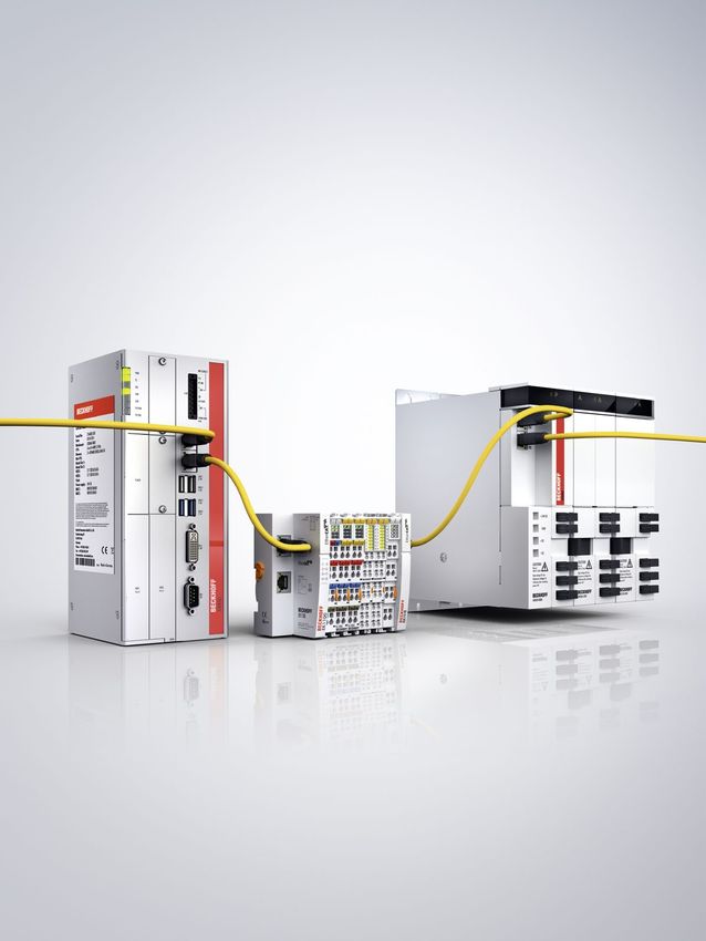
EtherCAT
EtherCAT
The real-time Ethernet fieldbus 43
u www.beckhoff.com/EtherCAT
44 Product overview 46 Technologies EtherCAT components
46 EtherCAT 1 24 Industrial PC
54 XFC 1 192 Embedded PC
58 EtherCAT P 78 EtherCAT Terminals
62 EtherCAT G 272 EtherCAT Box
75 Safety over EtherCAT 390 EtherCAT Plug-in Modules
632 Infrastructure Components
1 348 EtherCAT Servo Drives
1 490 TwinCAT
66 EtherCAT Development 1 570 TwinSAFE
Products 658 Accessories
67 EtherCAT ASIC
68 EtherCAT IP core
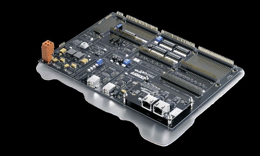
70 EtherCAT evaluation kit
71 EtherCAT piggyback
controller boards
73 EtherCAT P Sample Box
74 Industrial Ethernet
multi-channel probe
75 Safety over EtherCAT
Conformance Test Tool
76 EtherCAT development
software and tools
739 EtherCAT Developer
Trainings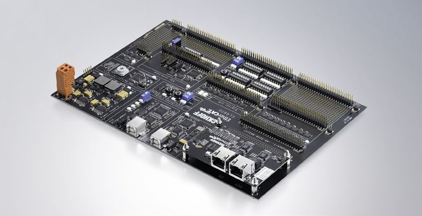
Product overview EtherCAT
EtherCAT
44
EtherCAT components
PC-based Control EtherCAT Terminals EtherCAT Box EtherCAT P Box
Industrial CPxxxx 1 38 Couplers EK1xxx 108 Digital I/O EP1xxx, 292 Digital I/O EPP1xxx 348
PCs Panel PCs EtherCAT Coupler E-bus ER1xxx, EQ1xxx* digital input
(EtherCAT masters) digital input
BK1xxx 119 EP2xxx, 299 EPP2xxx 354
Cxxxx 1 90 EtherCAT Coupler K-bus ER2xxx, EQ2xxx* digital output
control cabinet PCs digital output
(EtherCAT masters) EKxxxx 120 EP23xx, 307 EPP23xx 360
Bus Coupler for ER23xx, EQ23xx* digital combi
EtherCAT Terminals digital combi
Analog I/O EP3xxx, 314 Analog I/O EPP3xxx 366
Embedded CXxxxx 1 192 EK1400 117 ER3xxx, EQ3xxx* analog input
PCs Embedded PCs EtherCAT G analog input
(EtherCAT masters) EP4xxx, 322 EPP4xxx 370
Digital I/O EL1xxx 124 ER4xxx* analog output
digital input analog output
EP43xx 323 EPP43xx 371
Software TwinCAT 1 490 EL2xxx 138 analog combi analog combi
PLC/Motion EtherCAT masters and digital output Special EP5xxx, 326
Control development environment functions ER5xxx* Special EPP5xxx 372
Analog I/O EL3xxx 162 position measurement functions position measurement
analog input EP6xxx, 330
ER6xxx* EPP6xxx 375
Safety TwinSAFE 1 570 ELM3xxx 194 communication communication
open and scalable measurement modules EP7xxx, 334
control technology ER7xxx* motion EPP7xxx 377
EL4xxx 206 EP8xxx, 339 motion
analog output ER8xxx*
multi-functional I/O box System EPP1111 379
Redun- TwinCAT 1 535 Special EL5xxx 214 System EP1111 340 EtherCAT P Box with
dancy EtherCAT functions position measurement EtherCAT Box with ID switch ID switch
Redundancy EP1122 340 EPP1322 380
extension of the EtherCAT EL6xxx 219 2-port EtherCAT junction 3 ports, with feed-in
master with cable communication Fieldbus IL230x-B110 581 EPP1332 380
redundancy capability Box IP 67 Coupler Box with 3 ports, with refresh
EL7xxx 240 EtherCAT interface EPP1342 380
motion IExxxx 600 3 ports
Extension Box modules EPP9001 381
System EL9xxx 247 for IP-Link EtherCAT P/EtherCAT
system terminals Fieldbus FM33xx-B110 628 connector with power
modules Thermocouple transmission
Fieldbus Modules with EPP9022 381
EtherCAT interface 4 x diagnostics (US, UP, IS, IP)
*EPxxxx: industrial housing in IP 67, ERxxxx: zinc die-cast housing in IP 67, EQxxxx: stainless steel housing in IP 69K
We reserve the right to make technical changes.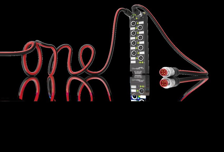
EtherCAT
45
EtherCAT Plug-in Modules Infrastructure Components Drive Technology Drive Technology
Couplers EJ1100 397 PCI FC9xxx 654 Servo AX5000 1 360 Servo- AM80xx 1 386
EtherCAT Coupler E-bus Ethernet PCI, Mini PCI, Drives Digital Compact motors Synchronous Servomotors
PCIe cards 1 Gbit/s Servo Drive with One Cable Technology
(OCT)
FC9xxx 655 AX8000 1 350 AM85xx 1 398
Digital I/O EJ1xxx 398 PCI, Mini PCI, multi-axis servo system Synchronous Servomotors
digital input PCIe cards 100 Mbit/s for OCT motors with increased rotor
moment of inertia and
EJ2xxx 402 PCI FC1100 646 EL72xx-9014 242 One Cable Technology (OCT)
digital output EtherCAT PCI EtherCAT slave card servomotor terminal, AM8700 1 412
Irms = 4.5 A, 50 V DC, servomotors with anodized
FC1121 646 OCT, STO housing and One Cable
PCIe EtherCAT slave card Technology (OCT)
Analog I/O EJ3xxx 406 EP7211-9034 334 AM88xx 1 416
analog input Port CU2508 639 servomotor box, stainless steel Synchronous
multiplier 1 x RJ45 Irms = 4.5 A, 50 V DC, Servomotors with One
EJ4xxx 410 (+ 8 x RJ45: 100 Mbit/s) OCT, STO Cable Technology (OCT)
analog output Linear AA2518 1 427
EtherCAT CU1128 641 EJ7211-9414 418 motors tubular motor
junction 8 x RJ45, IP 20 servomotor module, ALxxxx 1 428
Irms = 4.5 A, 50 V DC, Linear Servomotors
Special EJ5xxx 412 EP9128-0021 641 OCT, STO Compact AA112x, 1 440
functions position measurement 8 x M8, IP 67 Drive AA182x
Technology linear actuators
EJ6xxx 414 EtherCAT G CU1411 642 Distributed AMP8000 1 374 AM81xx 1 442
communication branch controller, 1 port Servo Drive Synchronous Servomotors Synchronous Servomotors
system with integrated servo drive with One Cable Technology
EJ7xxx 417 CU1418 642 (OCT) for the servo I/Os
motion branch controller, 8 ports AS20xx 1 448
stepper motors
CU1423 643 Intelligent XTS 1 458
junction, 3 x RJ45 transport Standard
System EJ9xxx 420 systems eXtended Transport System
system modules EtherCAT CU1521-0000 644 XTS 1 466
media multimode, IP 20 Hygienic
converter eXtended Transport System
fibre optic EP9521-0020 645 in stainless steel (IP 69K)
multimode, IP 67 XPlanar 1 472
eXtended planar
motor system
We reserve the right to make technical changes.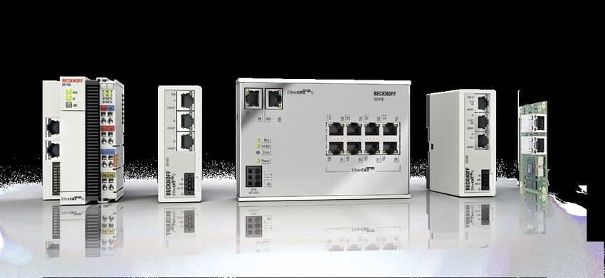
EtherCAT | Ultra-fast
EtherCAT

           communication standard
46

           u   www.ethercat.org

           How it works                        Network performance               Flexible topology                  Versatile
           The key functional principle of     The unique way EtherCAT           An EtherCAT network can            Factory-wide communication:
           EtherCAT lies in how its nodes      processes frames makes it         support up to 65,535 devices       EtherCAT is suitable for both
           process Ethernet frames: each       the fastest Industrial Ethernet   without placing restrictions       centralised and decentralised
           node reads the data addressed       technology.                       on their topology: line, bus,      system architectures.
           to it and writes its data back to                                     tree, star – or any combination
           the frame all while the frame is                                      thereof.
           moving downstream.

                                                                                 Functional safety
                                                                                 Safety over EtherCAT is just       Open technology
                                                                                 like EtherCAT itself – lean        EtherCAT is an internatio-
           Easy                                Low-cost                          and fast. Functional safety is     nally standardised open
           EtherCAT is easier than             EtherCAT delivers all of          built directly into the bus with   technology, meaning anyone
           classic fieldbus systems via        the advantages of Industrial      options for both centralised       is free to use the technology
           on-board diagnostics with           Ethernet at fieldbus prices:      and decentralised safety logic.    in a compatible form. Today,
           fault localisation, automatic       no active infrastructure          Thanks to the Black Channel        the EtherCAT Technology
           node addressing and no              components, no special            approach, it is also available     Group is the world’s largest
           need for network tuning.            hardware in the master.           for other bus systems.             fieldbus organisation.

                                                                                                                    We reserve the right to make technical changes.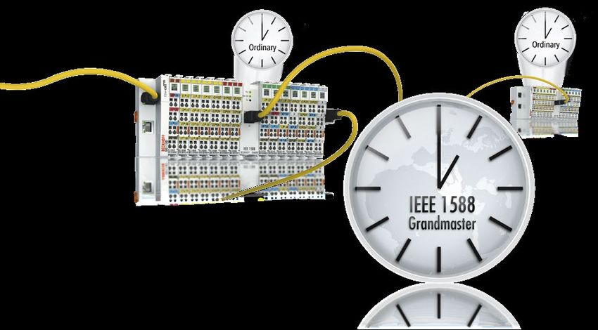
EtherCAT
                                                                                                                                            47

2003 | Introduction of EtherCAT technology        2003 | EtherCAT Technology Group founded        2005 | Safety over EtherCAT
at Hannover Messe                                 at SPS IPC Drives

Global standard                                   retained. As a result, devices from the early
In 2003, Beckhoff introduces its EtherCAT         years, even from as far back as 2003, are
technology into the market. The EtherCAT          still interoperable with today’s devices in
Technology Group (ETG) is formed, sup-            the same networks.
ported initially by 33 founder members.                 Another milestone is achieved in
The ETG goes on to standardise and main-          2016 with EtherCAT P, which introduces
tain the technology. The group is the largest     the ability to carry power (2 x 24 V) on a
fieldbus user organisation in the world,          standard Cat.5 cable alongside EtherCAT
with more than 5000 members (as of 2019)          data. This paves the way for machines
currently. In 2005, the Safety over EtherCAT      without control cabinets.
protocol is rolled out, expanding the EtherCAT          The launch of EtherCAT G/G10 in 2018
specification to enable safe transmission of      introduces higher data transmission rates.
safety-relevant control data. The low-foot-       Interoperability with the existing EtherCAT
print protocol uses a so-called Black Channel,    equipment base is a core requirement,
making it completely independent of the           so steps are taken to enable integration,
communication system used.                        including introduction of the so-called
     In 2007, EtherCAT is adopted as an           branch model.
IEC standard, underscoring how open
the system is. To this day, the specification
remains unchanged; it has only been
extended and compatibility has been

2007 | EtherCAT is IEC standard.                  2016 | EtherCAT P: Ultra-fast communication     2018 | EtherCAT G: The next performance
                                                  and power via one cable                         level with 1 Gbit/s

We reserve the right to make technical changes.
EtherCAT

48

                         Ethernet header                ECAT                                EtherCAT telegram                                        Ethernet

                   DA          SA          Type      Frame HDR             Datagram 1           Datagram 2             Datagram n               Pad.            FCS

                   (6)         (6)         (2/4)            (2)             (10+n+2)             (10+m+2)               (10+k+2)             (0…32)              (4)
                         Ethertype 0x88A4

           EtherCAT in a standard Ethernet frame (according to IEEE 802.3)

           The technology in detail
           EtherCAT: Based on Ethernet                            the transmission of the actual values             forward frames downstream. This concept
           Technology                                             after receiving the target values. At the         prevents unpredictable delays and guaran-
           EtherCAT is an Industrial Ethernet                     end, not much of the 100 Mbit/s transfer          tees real-time capabilities.
           system that utilises standard frames                   rate remains.                                          The master uses a standard Ethernet
           and the physical layer as defined in                        Protocol stacks, such as those used          Media Access Controller (MAC) without
           the Ethernet standard IEEE 802.3.                      in the IT world for routing (IP) and connection   an additional communication processor.
           However, it also addresses the specific                (TCP), require additional overhead for each       This allows a master to be implemented
           demands faced in the automation                        node and create further delays through            on any hardware platform with an avail-
           industry, where:                                       the stack runtimes.                               able Ethernet port, regardless of which
           – There are hard real-time requirements                                                                  real-time operating system or application
                with deterministic response times.                How does EtherCAT work?                           software is used.
           – The system is usually made up of                     EtherCAT overcomes the typical short-                  EtherCAT slave devices use a so-
                many nodes, each only having a                    comings of Industrial Ethernet with               called EtherCAT Slave Controller (ESC) to
                small amount of cyclic process data.              its high-performing mode of operation,            process frames on the fly and entirely in
           – Hardware costs are even more                         in which a single frame is usually suffi-         hardware, making network performance
                important than in IT and office                   cient to send and receive control data            predictable and independent of the indi-
                applications.                                     to and from all nodes.                            vidual slave device implementation.
           The above requirements make using a                         The EtherCAT master sends a telegram
           standard Ethernet network at the field                 that passes through each node. Each EtherCAT      The EtherCAT protocol
           level practically impossible. If an individual         slave device reads the data addressed to it       EtherCAT embeds its payload in a standard
           Ethernet telegram is used for each node,               “on the fly,” and inserts its data in the frame   Ethernet frame. The EtherCAT frame is identi-
           the effective data rate sinks significantly            as the frame is moving downstream. The            fied with the Identifier (Ox88A4) in the
           for just a few bytes of cyclic process data:           frame is delayed only by hardware propa-          Ethertype field. Since the EtherCAT protocol
           the shortest Ethernet telegram is 84 bytes             gation delay times. The last node in a seg-       is optimised for short cyclic process data,
           long (including the Inter Frame Gap), of               ment or branch detects an open port and           the use of bulky protocol stacks, such as
           which 46 bytes can be used for process                 sends the message back to the master using        TCP/IP or UDP/IP, can be eliminated.
           data.                                                  Ethernet technology’s full duplex feature.             To ensure Ethernet IT communication
                For example, if a drive sends 4 bytes                  The telegram’s maximum effective             between the nodes, TCP/IP connections can
           of process data for the actual position                data rate increases to over 90 %, and due         optionally be tunneled through a mailbox
           and status information and receives                    to the utilisation of the full duplex feature,    channel without impacting real-time data
           4 bytes of data for the target position                the theoretical effective data rate is even       transfer.
           and control information, the effective                 greater than 100 Mbit/s.                               During startup, the master device config-
           data rate for both telegrams sinks to                       The EtherCAT master is the only node         ures and maps the process data on the slave
           4/84 = 4.8 %. Additionally, the drive                  within a segment allowed to actively send         devices. Different amounts of data can be
           usually has a reaction time that triggers              an EtherCAT frame; all other nodes merely         exchanged with each slave, from one bit to

                                                                                                                                   We reserve the right to make technical changes.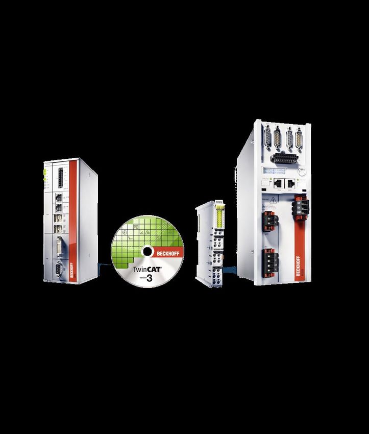
EtherCAT
                                                                                                                                                          49

                     Ethernet header              ECAT HDR          Datagram 1            Datagram 2             Datagram 3         Ethernet

                                                                  Logical Process       Logical Process        Logical Process
                                                                  Image Task 1          Image Task 2           Image Task 3

Inserting process data on the fly

a few bytes, or even up to kilobytes of                      controller, and copied into memory. With           cation depends on the network’s
data.                                                        EtherCAT, the master device only needs             topology, and is particularly suitable
     The EtherCAT frame contains one or                      to fill a single EtherCAT frame with new           for slave-to-slave communication in
more datagrams. The datagram header indi-                    output data, and send the frame via                a constant machine design (e.g. in
cates what type of access the master device                  automatic Direct Memory Access (DMA)               printing or packaging machines).
would like to execute:                                       to the MAC controller.                                  In contrast, freely configurable
– read, write, or read-write                                      When a frame with new input data              slave-to-slave communication runs
– access to a specific slave device                          is received via the MAC controller, the            through the master device, and requires
     through direct addressing, or                           master device can copy the frame again             two bus cycles (not necessarily two
     access to multiple slave devices                        via DMA into the computer’s memory –               control cycles). Through the excellent
     through logical addressing                              all without the CPU having to actively copy        performance of EtherCAT, this type of
     (implicit addressing)                                   any data. In addition to cyclical data, further    slave-to-slave communication is still
Logical addressing is used for the cyclical                  datagrams can be used for asynchronous             faster than with other communication
exchange of process data. Each datagram                      or event driven communication.                     technologies.
addresses a specific part of the process                          In addition to logical addressing, the
image in the EtherCAT segment, for which                     master device can also address a slave device
4 GB of address space is available. During                   via its position in the network. This method
network startup, each slave device is                        is used during network boot up to determine
assigned one or more addresses in this                       the network topology and compare it to the
global address space. If multiple slave                      planned topology. After checking the network
devices are assigned addresses in the                        configuration, the master device can assign
same area, they can all be addressed with                    each node a configured node address and
a single datagram.                                           communicate with the node via this fixed
     Since the datagrams completely contain                  address.
all the data access related information, the                      This enables targeted access to
master device can decide when and which                      devices, even when the network topo-
data to access. For example, the master                      logy is changed during operation, for
device can use short cycle times to refresh                  example with Hot Connect Groups.
data on the drives, while using a longer cycle               There are two approaches for slave-
time to sample the I/O; a fixed process data                 to-slave communication. A slave device
structure is not necessary. This also relieves               can send data directly to another slave
the master device in comparison to con-                      device that is connected further down-
ventional fieldbus systems, in which the                     stream in the network. Since EtherCAT
data from each node had to be read indivi-                   frames can only be processed going
dually, sorted with the help of the process                  forward, this type of direct communi-

We reserve the right to make technical changes.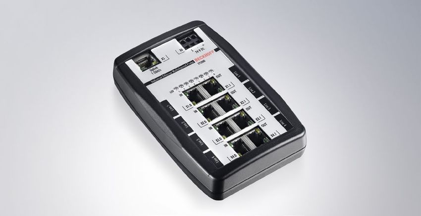
EtherCAT

50

           Flexible topology – line, tree or star

           Flexible topology                              data and power via one cable. This option     an embedded Industrial PC, since extension
           Line, tree, star, or daisy-chain: EtherCAT     enables the connection of devices such        slots are no longer necessary. In the past,
           supports almost all topologies. EtherCAT       as sensors with a single line. Fibre optics   extension slots were also required to connect
           makes a pure bus or line topology with         (such as 100BASE-FX) can also be used, for    complex devices, such as fieldbus master
           hundreds of nodes possible without the         example for a node distance greater than      and slave gateways, fast serial interfaces,
           limitations that normally arise from cas-      100 m. The complete range of Ethernet         and other communication subsystems.
           cading switches or hubs.                       wiring is also available for EtherCAT.        In EtherCAT, all that is needed to connect
                When wiring the system, the combi-             Up to 65,535 devices can be connected    these devices is a single Ethernet port.
           nation of lines with branches or drop          to one EtherCAT segment, so network           The process data from the underlying
           lines is particularly beneficial: the ports    expansion is virtually unlimited. Because     subsystem is made directly available in
           necessary to create branches are directly      of the practically unlimited number of        the process image of the EtherCAT system.
           integrated in many I/O modules, so no          nodes, modular devices such as “sliced”
           additional switches or active infrastructure   I/O stations can be designed in such a        Distributed clocks for high-precision
           components are required. The star topology,    way that each module is an EtherCAT           synchronisation
           the Ethernet classic, can also naturally be    node of its own. Hence, the local extension   In applications with spatially distributed
           utilised.                                      bus is eliminated; the high performance       processes requiring simultaneous actions,
                Modular machines or tool changers         of EtherCAT reaches each module directly      exact synchronisation is particularly impor-
           require network segments or individual         and without any delays, since there is now    tant. For example, this is the case for appli-
           nodes to be connected and disconnected         no gateway in the bus coupler or head         cations in which multiple servo axes exe-
           during operation. EtherCAT slave con-          station.                                      cute coordinated movements.
           trollers already include the basis for this                                                       In contrast to completely synchronous
           Hot Connect feature. If a neighbouring         Integration of other bus systems              communication, whose quality suffers
           station is removed, then the port is auto-     The ample bandwidth of EtherCAT makes         immediately from communication errors,
           matically closed so the rest of the network    it possible to embed conventional fieldbus    distributed synchronised clocks have a
           can continue to operate without interfer-      networks as an underlying system via an       high degree of tolerance for jitter in the
           ence. Very short detection times < 15 μs       EtherCAT Gateway, which is particularly       communication system. Therefore, the
           guarantee a smooth changeover.                 helpful when migrating from a conventional    EtherCAT solution for synchronising nodes
                EtherCAT offers a lot of flexibility      fieldbus to EtherCAT. The changeover to       is based on such distributed clocks (DC).
           regarding cable types, so each segment         EtherCAT is gradual, making it possible to         The calibration of the clocks in the
           can use the exact type of cable that best      continue using automation components          nodes is completely hardware-based.
           meets its needs. Inexpensive Industrial        that do not yet support an EtherCAT inter-    The time from the first DC slave device
           Ethernet cables can be used between two        face.                                         is cyclically distributed to all other devices
           nodes up to 100 m apart in 100BASE-TX               The ability to integrate decentralised   in the system. With this mechanism,
           mode. Furthermore, the protocol addition       gateways also reduces the physical size       the slave device clocks can be pre-
           EtherCAT P enables the transmission of         of the Industrial PC, sometimes even to       cisely adjusted to this reference clock.

                                                                                                                       We reserve the right to make technical changes.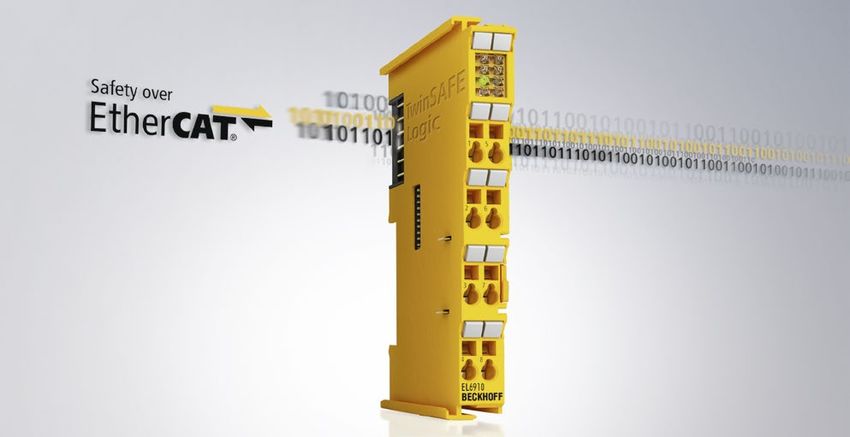
EtherCAT
                                                                                                                                                      51

Simple integration of other bus systems

The resulting jitter in the system is signifi-    the measured position, so it is critical that   and commissioning time. In addition to error
cantly less than 1 μs.                            the position measurements are taken pre-        detection, error localisation is important
    Since the time sent from the reference        cisely equidistantly (i.e. in exact cycles).    during troubleshooting. EtherCAT features
clock arrives at the slave devices slightly       Even very small inaccuracies in the position    the possibility to scan and compare the
delayed, this propagation delay must be           measurement timing can translate to larger      actual network topology with the planned
measured and compensated for each slave           inaccuracies in the calculated velocity,        topology during boot up. EtherCAT also
device in order to ensure synchronicity and       especially relative to short cycle times.       has many additional diagnostic capabilities
simultaneousness. This delay is measured          With EtherCAT, the position measurements        inherent to its system.
during network startup or, if desired, even       are triggered by the precise local clock             The EtherCAT Slave Controller in each
continuously during operation, ensuring           and not the bus system, leading to much         node checks the moving frame for errors
that the clocks are simultaneous to within        greater accuracy.                               with a checksum. Information is provided to
much less than 1 μs of each other.                     Additionally, the use of distributed       the slave application only if the frame has
    If all nodes have the same time infor-        clocks also unburdens the master device;        been received correctly. If there is a bit error,
mation, they can set their output signals         since actions such as position measurement      the error counter is incremented and the
simultaneously and affix their input signals      are triggered by the local clock instead of     subsequent nodes are informed that the
with a highly precise timestamp. In motion        when the frame is received, the master          frame contains an error. The master device
control applications, cycle accuracy is also      device does not have such strict require-       detects that the frame is faulty and discards
important in addition to synchronicity            ments for sending frames. This allows the       its information. The master device is able
and simultaneousness. In such applica-            master stack to be implemented in software      to detect where the fault originally occurred
tions, velocity is typically derived from         on standard Ethernet hardware. Even jitter      in the system by analysing the nodes’ error
                                                  in the range of several microseconds does       counters. This is an enormous advantage in
                                                  not diminish the accuracy of the distributed    comparison to conventional fieldbus systems,
                                                  clocks. Since the accuracy of the clock does    in which an error is propagated along the
                                                  not depend on when it is set, the frame’s       shared bus line, making it impossible to
                                                  absolute transmission time becomes irrel-       localise the source of the error. EtherCAT can
                                                  evant. The EtherCAT master need only to         detect and localise occasional disturbances
                                                  ensure that the EtherCAT telegram is sent       before the issue impacts the machine’s
                                                  early enough, before the DC signal in           operation.
                                                  the slave devices triggers the output.               Due to the unique principle of band-
                                                                                                  width utilisation of EtherCAT, which is
                                                  Diagnostics and error localisation              orders of magnitude better than indus-
                                                  Experience with conventional fieldbus           trial Ethernet technologies that use single
Synchronicity and simultaneousness –              systems has shown that diagnostic               frames, the likelihood of disturbances
scope view of two distributed devices             characteristics play a major role in            induced by bit errors within an EtherCAT
with 300 nodes and 120 m cable length             determining a machine’s availability            frame is substantially lower – if the same

We reserve the right to make technical changes.
M
t S
EtherCAT
52
S S S S S S
Completely hardware-based
synchronisation with compensation
for propagation delays
cycle time is used. And, if in typical High availability requirements
EtherCAT fashion much shorter cycle For machines or equipment with very high
times are used, the time required for availability requirements, a cable break or
error recovery is significantly reduced. a node malfunctioning should not mean
Thus, it is also much simpler to master that a network segment is no longer
such issues within the application. accessible, or that the entire network fails.
Within the frames, the Working Counter EtherCAT enables cable redundancy with
enables the information in each datagram simple measures. By connecting a cable
to be monitored for consistency. Every node from the last node to an additional Ethernet
that is addressed by the datagram and port in the master device, a line topology
whose memory is accessible increments is extended into a ring topology. A redun-
the Working Counter automatically. The dancy case, such as a cable break or a node
master is then able to cyclically confirm malfunction, is detected by a software
if all nodes are working with consistent add-on in the master stack. That is all there
data. If the Working Counter has a different is to it. The nodes themselves do not need
value than it should, the master does not to be modified, and do not even “know”
forward this datagram’s data to the control that they are being operated in a redundant
application. The master device is then able network.
to automatically detect the reason for the Link detection in the slave devices auto-
unexpected behaviour with help from status matically detects and resolves redundancy
and error information from the nodes as cases with a recovery time less than 15 μs,
Industrial PC
well as the Link Status. so at maximum, a single communication
Since EtherCAT utilises standard cycle is disrupted. This means that even
Ethernet frames, Ethernet network traffic motion applications with very short cycle
can be recorded with the help of free times can continue working smoothly when
Ethernet software tools. For example, a cable breaks.
the well-known Wireshark software With EtherCAT, it is also possible to
comes with a protocol interpreter for realise master device redundancy with
EtherCAT, so that protocol-specific infor- Hot Standby. Vulnerable network compo-
mation, such as the Working Counter, nents, such as those connected with a
commandos, etc. are shown in plain text. drag chain, can be wired with a drop line,
so that even when a cable breaks, the
rest of the machine keeps running.
Inexpensive cable redundancy with
standard EtherCAT slave devices
We reserve the right to make technical changes.EtherCAT
53
The EtherCAT Technology Group
is a global organisation.
EtherCAT Technology Group stable and interoperable. The ETG holds release. The ETG awards the manufacturer
The EtherCAT Technology Group (ETG) multiple Plug Fests in Europe, Asia, and a Conformance Certificate following a
keeps EtherCAT technology open for America each year. The Plug Fests bring successful test in an accredited test lab.
all potential users. It brings EtherCAT EtherCAT device developers together
device manufacturers, technology pro- to test and ensure device interoperability.
viders, and users together to further Using the official EtherCAT Conformance
the technology. They are focused on Test Tool, each manufacturer conformance
one common goal: keeping EtherCAT tests its EtherCAT devices prior to their
Ordering information Components for EtherCAT technology implementation
FB1111 EtherCAT piggyback controller board with ET1100 71
ET9400 one-year license for using the EtherCAT Conformance Test Tool 77
ET9300 license for using the EtherCAT Slave Stack Code (free download from Beckhoff website via Member Area
of the EtherCAT Technology Group web page) 77
ET9200 license for using the EtherCAT Master Sample Code 76
ET9000 license for using the EtherCAT configurator 76
ET2000 Industrial Ethernet multi-channel probe 74
ET1815 | ET1816 EtherCAT IP core for Xilinx® FPGAs 69
ET1810 | ET1811 EtherCAT IP core for Intel® FPGAs 68
ET1100-0000 EtherCAT ASIC 67
EL9820 EtherCAT evaluation kit with FB1111-0142, ASIC ET1100 70
Ordering information Training courses for the EtherCAT technology implementation
TR8110 training, EtherCAT technology basics for developers 739
TR8100 EtherCAT evaluation workshop for slave developers 739
TR8200 EtherCAT Master Sample Code workshop for master developers 739
We reserve the right to make technical changes.EtherCAT | Even faster with XFC
EtherCAT
54
u www.beckhoff.com/XFC
TwinCAT – The extremely fast EtherCAT – The extremely fast
real-time control software control communication technology
– real-time under Microsoft Windows – 1000 distributed digital I/Os in 30 μs
down to 12.5 μs cycle time – EtherCAT down to the individual
– standard IEC 61131-3 programming I/O terminals, no sub bus required
in XFC real-time tasks – optimised use of standard Ethernet
– Standard features of Windows Controllers, e.g. Intel® PC chipset
and TwinCAT are XFC-compliant. architecture in the EtherCAT master
– advanced real-time features based
on distributed clocks
– synchronisation
– timestamping
– oversampling
Industrial PC – The extremely EtherCAT Terminals –
fast control CPU The extremely fast I/O technology
– Industrial PC based on – full range I/O line for all signal types
high-performance real-time – high-speed digital and analog I/Os
motherboards – Timestamping and oversampling
– compact form factors optimised features allow extremely high timing
for control applications resolution (down to 10 ns).
We reserve the right to make technical changes.EtherCAT
55
Higher production efficiency with XFC offers a further reduction of response can simply be integrated in the machine
extremely fast control technology times by a factor of 10, and enables cycle control without additional, costly special
With XFC technology (eXtreme Fast Control) times of 100 μs and below, without having devices.
Beckhoff presents an ultra fast control to give up central intelligence and associ- In a practical automation solution,
solution: XFC is based on optimised control ated high-performance algorithms. XFC not everything has to be extremely fast
and communication architectures comprising also includes additional technologies that and accurate – many tasks can still be
an advanced Industrial PC, ultra-fast I/O ter- not only improve cycle times, but also tem- handled with “normal” solutions. XFC
minals with extended real-time character- poral accuracy and resolution. technology is therefore fully compatible
istics, the EtherCAT high-speed Ethernet Users benefit from options for enhancing with existing solutions and can be used
system, and the TwinCAT automation soft- the quality of their machines and reducing simultaneously with the same hardware
ware. With XFC it is possible to achieve response times. Measuring tasks such as pre- and software.
I/O response times < 100 μs. This technology ventive maintenance measures, monitoring
opens up new process optimisation oppor- of idle times or documentation of parts quality
tunities for the user that were not possible
in the past due to technical limitations.
XFC represents a control technology
that enables very fast and highly deter-
ministic responses. It includes all hardware
and software components involved in
control applications: optimised input and
output components that can detect signals
with high accuracy or initiate tasks;
EtherCAT as very fast communication
network; high-performance Industrial
PCs; and TwinCAT, the automation soft-
ware that links all system components.
Not long ago, control cycle times
around 10 to 20 ms were normal. The com-
munications interface was free-running,
with corresponding inaccuracy of the deter-
minism associated with responses to pro-
cess signals. The increased availability
of high-performance Industrial PC control-
lers enabled a reduction in cycle times The I/O response time includes all hardware
down to 1–2 ms, i.e. by about a factor processing times (Industrial PC, EtherCAT and
of 10. Many special control loops could I/O system), ranging from physical input event
thus be moved to the central machine to output response. With an I/O response time
controller, resulting in cost savings and of < 100 μs, PLC programmers have access to
greater flexibility in the application of performance that in the past was only avail-
intelligent algorithms. able in servo controllers with digital signal
processors.
We reserve the right to make technical changes.EtherCAT
56
The EtherCAT distributed clocks are a basic XFC technology and a general component of EtherCAT communication.
XFC technologies
Distributed clocks also referred to as system time, because it Signal technology for terminals with
In a normal, discrete control loop, actual is always available across the whole system. timestamping (64-bit time resolution):
value acquisition occurs at a certain time – extremely precise time measurement
(input component), the result is transferred Features: for digital single shot events per cycle:
to the control system (communication com- – distributed absolute system resolution 1 ns, internal sampling 10 ns,
ponent), the response is calculated (control synchronisation for CPU, accuracy with distributed clocksCentral control Central control
EtherCAT
Central control Central control 57
1 1 1 1
Subordinate special control Fast central control
Subordinate special controls offer a limited process image. XFC enables fast central control with a complete process image.
Oversampling – down to 10 μs time resolution Extremely fast I/O response time:
Process data is usually transferred exactly – support of digital I/O EtherCAT – from 85 μs
once per communication cycle. Conversely, Terminals – Deterministic synchronised input
the temporal resolution of a process record – up to 1 MHz and output signal conversion leads
directly depends on the communication – up to 1 μs time resolution to low process timing jitter.
cycle time. Higher temporal resolution is – application – Process timing jitter is independent
only possible through a reduction in cycle – fast signal monitoring of communication and CPU jitter.
time – with associated practical limits. – fast function generator output
Oversampling data types enable multiple – signal sampling independent Extremely short control cycle time:
sampling of a process record within a com- of cycle time – 100 μs (min. 12.5 μs)
munication cycle and subsequent (inputs) – fast loop control – new performance class for PLC
or prior (outputs) transfer of all data con- application: control loops with 100 μs
tained in an array. The oversampling factor Fast I/Os
describes the number of samples within a Very fast physical responses require suitably
communication cycle and is therefore a short control cycle times in the associated
multiple of one. Sampling rates of 200 kHz control system. A response can only take
can easily be achieved, even with moderate place once the control system has detected
communication cycle times. and processed an event.
Triggering of the sampling within the The traditional approach for achieving
I/O components is controlled by the local cycle times in the 100 μs range relies on
clock (or the global system time), which special separate controllers with their own,
enables associated temporal relationships directly controlled I/Os. This approach has
between distributed signals across the clear disadvantages, because the separate
whole network. controller has only very limited information
about the overall system and therefore
Features signal oversampling: cannot make higher-level decisions. Repa-
– multiple signal conversion within rameterisation options (e.g. for new work-
one control cycle pieces) are also limited. Another significant
– hard time synchronisation through disadvantage is the fixed I/O configuration,
distributed clocks which generally cannot be expanded.
– for digital input/output signals
– for analog input/output signals
– support of analog I/O EtherCAT
Terminals
– up to 100 kHz signal conversion
We reserve the right to make technical changes.EtherCAT P | Ultra-fast communication
EtherCAT
and power in one cable
58
u www.beckhoff.com/EtherCATP
The same free and flexible Minimised installation space Forwarding of power
choice of topology well-known in drag chains, control supply in the devices
from EtherCAT is also available cabinets and machines
with EtherCAT P.
Outstanding EtherCAT One Cable Connection: Highly scalable connec-
Reduced material performance at low EtherCAT + 2 x 24 V DC tor family from 24 V DC
and assembly costs connection costs (UP, US) on just 4 wires to 630 V AC/850 V DC
We reserve the right to make technical changes.EtherCAT
59
EPPxxxx | EtherCAT P EPPxxxx-006x | Compact EK13xx | EtherCAT P ENP/ECP | Connector family
products in IP 67 EtherCAT P products in IP 67 products in IP 20 for all applications
EtherCAT P (P = power) is an addition to the the user can cascade several EtherCAT P tional power pins, resulting in the ENP/
EtherCAT protocol standard. It enables not devices and therefore only needs one cable. ECP connectors B12, B17, B23 and B40 for
only the transmission of communication data, This facilitates reduced cabling, more com- different performance classes. Featuring a
but also the peripheral voltage via a single, pact, cost-effective wiring, lower system bayonet fitting and IP 67 protection rating,
standard four-wire Ethernet cable. costs and a smaller footprint for devices, they enable simple, fast and reliable connec-
EtherCAT and EtherCAT P are identical equipment and machines. tion directly at the machine and optimised
in terms of the protocol technology, as the scalability of EtherCAT for the following
addition exclusively affects the physical layer. EtherCAT P: From 24 V DC sensor applications:
No new EtherCAT Slave Controllers are nec- to 630 V AC/850 V DC drive – B12 for connecting compact motors
essary when using EtherCAT P. EtherCAT P EtherCAT P offers benefits both for connect- with integrated output stages,
has the same communication advantages ing remote, smaller I/O stations in terminal for up to 48 V DC and 10 A
as EtherCAT, but also provides the power boxes and I/O components distributed in – B17 for asynchronous motors
supply via the communication cable, offer- the process. A complete connector family with frequency converter,
ing attractive benefits and enhancements was developed, so that the One Cable Auto- for up to 230 V DC and 14 A
for numerous applications. mation concept can also be used for connect- – B23 for complete control cabinets,
Two electrically isolated, individually ing components with higher voltage and/or for up to 400 V AC and 30 A
switchable 24 V supplies power the current requirements. The ENP/ECP connector – B40 for the supply of robot stations,
EtherCAT P devices, available with US serv- family is designed to cover all applications for up to 64 A
ing the system and sensors and UP serving up to drives with 650 V AC or 850 V DC and
the periphery and actuators. Both volt- up to 64 A.
ages, US and UP, are directly coupled into For higher loads, a compact EtherCAT P
the 100 Mbit/s EtherCAT communication element with the same pin assignment as
line. Thanks to this power transmission, the M8 connector was equipped with addi-
Technical data EtherCAT P
Voltages 2 x 24 V DC according to IEC 61131 (-15 %/+20 %), max. 3 A each per US and UP
Connectors Incorrect connections are ruled out with the P-coded M8 connector.
Topology cascadable in all topology variants
Network planning tool-based calculation of currents and voltages, resulting in optimum design and distribution of feed-in points
Process data EtherCAT process data scalable from 1 bit…64 kbyte per device
Devices up to 65,535 devices in one network
Performance cycle times of < 100 μs, distributed clocks synchronisationControl cabinet
EtherCAT
24 V DC 24 V DC 24 V DC
60
Machine module 2
EtherCAT P
to EtherCAT
EtherCAT P directly connects
different machine modules
with power and ultra-fast 24 V DC 24 V DC
communication in one cable.
EtherCAT P simplifies system cabling
The fundamental idea of EtherCAT P is bus, offering benefits for connecting smaller or 2 A output current), a wide range of
to simplify system wiring by reducing remote I/O stations in terminal boxes as well 4-, 8- and 16-channel IP 67 I/Os with com-
the number of connectors on automation as I/O components distributed in the process bined digital inputs/outputs, as well as
components and devices. The single-cable environment. A special M8 connector was serial RS232 and RS422/RS485 interfaces.
solution, which is highly scalable according developed for this purpose, with mechanical In addition, there are EPP box modules
to individual power requirements, can be coding that reliably protects against mismat- for analog input and output parameters,
deployed on the entire field level: A con- ing with standard EtherCAT slaves. e.g. ±10 V/0 to 20 mA, differential/absolute
ventional standard Ethernet cable is used To be able to connect components with pressure, and data from resistance sensors,
for the 24 V range. For higher voltages and higher voltage and/or current supply needs, thermocouples and incremental encoders.
currents, EtherCAT P is integrated into the a complete EtherCAT P connector family has
corresponding power cable. For this purpose, been designed: the ECP/ENP connector fam- Flexible topology
Beckhoff offers the ENP/ECP connector family, ily covers all applications up to drives with EtherCAT P topologies are just as freely
which includes a comprehensive range of 630 V AC or 850 V DC and 64 A ratings and selectable and customisable as with
cables and connectors. enables efficient connection of all field level EtherCAT. The current carrying capacity
Eliminating the need for separate supply components. For I/O connection, interfaces of 3 A per EtherCAT P segment enables
cables reduces material costs, installation in IP 20 and IP 67 ratings are available. a wide range of sensors/actuators to be
effort and time, as well as the risks of instal- The system is also suitable for actuators used. The IP 67 infrastructure components
lation errors. In addition, the installation such as AC and DC motors, valve terminals, can be used for creating the required
space required in drag chains, control cabi- and sensors, such as proximity switches, network structure directly in the field.
nets and in the machine itself is minimised. light barriers or rotary encoders. Cameras, EtherCAT P can be used in the same
Moreover, cable routes become smaller bar code scanners and 3D scanners can be network together with standard EtherCAT
and less cluttered, and the size of sensors integrated for machine vision applications. technology. Appropriate rectifier units
and actuators can be reduced. Overall, this transform common EtherCAT physics to
opens up significantly more freedom in EtherCAT P Box modules for all EtherCAT P by consistently maintaining
system design, while minimising material data acquisition requirements the Ethernet data encoding. In the same
or system costs, which can be further redu- For the 24 V I/O level, a complete range of way, a device itself can be supplied with
ced using specific tools for system planning. system and I/O components is already avail- EtherCAT P but, in turn, can also transmit
able with IP 67 rating. The entire variety the EtherCAT protocol.
EtherCAT P – the ideal sensor, of tried and tested EP Box modules is also
actuator and measurement bus available in EPP format with EtherCAT P
With EtherCAT P, the US and UP currents are technology for connecting sensors and
directly fed into the wires of the 100 Mbit/s actuators. These include different 4-, 8-
line, resulting in a very cost-effective and and 16-channel digital input modules
compact connection. This makes EtherCAT P (3.0 ms or 10 μs filter), 4-, 8-, 16- and
the ideal sensor, actuator and measurement 24-channel digital output modules (0.5 A
We reserve the right to make technical changes.Machine module 1
EtherCAT
61
Machine module 3 Machine module 4
24 V DC
Connecting the IP 20 world supply US or the peripheral voltage for actua- EtherCAT P or extension of an EtherCAT P
The IP 20 EK13xx EtherCAT P Couplers enable tors UP can be bridged to the power contacts. network. Terminal points are used for system
EtherCAT P to be used all the way through, The 2-port EK1322 EtherCAT P junction and sensor supply US and the peripheral
from the control cabinet right to the machine. enables the configuration of EtherCAT P voltage for actuators UP for the EtherCAT P
The EK1300 Coupler integrates EtherCAT star topologies. The ports can be used to output.
Terminals (ELxxxx) with an EtherCAT P net- connect individual EtherCAT P devices or
work. The upper EtherCAT P interface is used whole EtherCAT P segments. The EK1322 EPPxxxx EtherCAT P modules for
to connect the coupler to the network, while can be installed at any point in an EtherCAT the typical range of requirements
the lower P-coded M8 socket is used for opti- segment between the EtherCAT Terminals of IP 67 I/O signals see page 346
mal continuation of the EtherCAT P topology. (ELxxxx). The front terminal points are used
Since EtherCAT P integrates power supply for the system and sensor supply US, and Extensive portfolio of pre-assembled
and communication on a single line, an addi- the peripheral voltage for actuators UP for cables, cables sold by the metre
tional power supply for the coupler via the the EtherCAT P outputs. and connectors for EtherCAT P
terminal points is not required. Depending The EK1310 EtherCAT P extension see page 691
on the application, the system and sensor enables conversion from EtherCAT to
Ordering information Infrastructure components in IP 67 for EtherCAT P
EPP1111-0000 EtherCAT P Box, industrial housing, with ID switch 379
EPP1321-0060 EtherCAT P Box, industrial housing, 1-channel EtherCAT to EtherCAT P supply module 380
EPP1322-0001 EtherCAT P Box, industrial housing, 3-way junction with feed (EtherCAT IN, 3 x EtherCAT P OUT) 380
EPP1332-0001 EtherCAT P Box, industrial housing, 3-way junction with refresh (EtherCAT P IN, 3 x EtherCAT P OUT) 380
EPP1342-0001 EtherCAT P Box, industrial housing, 3-way junction without refresh (EtherCAT P IN, 3 x EtherCAT P OUT) 380
EPP9001-0060 EtherCAT P Box, industrial housing, EtherCAT P/EtherCAT, ECP/EC connector with power transmission 381
EPP9022-0060 EtherCAT P Box, industrial housing, 2 x diagnostics (US, UP) 381
EP9224-0037 EtherCAT Box, industrial housing, 4-channel power distribution box ENP to EtherCAT P 343
EP9221-0057 EtherCAT Box, industrial housing, 1-channel power distribution box ENP to EtherCAT P 343
Ordering information Infrastructure components in IP 20 for EtherCAT P
EK1300 EtherCAT P Coupler for E-bus terminals (ELxxxx) 118
EK1310 EtherCAT P extension 118
EK1322 2-port EtherCAT P junction 118
We reserve the right to make technical changes.EtherCAT G | Scalable I/O performance
EtherCAT
from 100 to 10,000 Mbit/s
62
u www.beckhoff.com/EtherCATG
EtherCAT EtherCAT G EtherCAT G10
– 100BASE-TX – 1000BASE-T – 10GBASE-T
– vast choice of components – integration of data- – integration of
intensive devices EtherCAT G segments
– very high bandwidth – ultimate bandwidth
Branch controller concept
– scalable processing on the fly
at 100 Mbit/s, 1 Gbit/s and 10 Gbit/s
– simple configuration
– universal diagnostics
– branch controller for integration of
EtherCAT into EtherCAT G/G10 networks
– optimisation of the propagation delay time
– integration of standard Ethernet segments
We reserve the right to make technical changes.EtherCAT
63
EK1400 | EtherCAT G CU1411 | EtherCAT G CU1418 | EtherCAT G CU1423 | EtherCAT G FB1400 | EtherCAT G
Coupler branch controller, 1-port branch controller, 8-port junction, 3-way piggyback controller board
Technology expansion for data- Product range for the implementation Universal EtherCAT features
intensive applications of the technology expansion – real-time Ethernet down to
EtherCAT G builds on the principles of The branch controller concept for EtherCAT G the I/O level
the successful EtherCAT technology but enables EtherCAT branches that allow paral- – flexible topology
moves the available data rates up to lel operation of 100 Mbit/s segments in a – outstanding diagnostics
1 Gbit/s and 10 Gbit/s. The EtherCAT 1 Gbit/s network through corresponding – synchronisation accuracy
protocol itself remains unchanged. transmission rates. The following products better than 100 ns
All of the devices on a network receive are available for this purpose: – exceptionally simple
the telegrams sent by the EtherCAT master. – EK1400 EtherCAT G Coupler for configuration
Each EtherCAT slave still reads the data coupling EtherCAT Terminals to an – low system costs
addressed to it “on the fly” and inserts its EtherCAT G network and EtherCAT G – maximum performance
own data into the frame as the frame moves branch controller functionality – ability to integrate functional
downstream; now, though, it does this at – CU1411 EtherCAT G branch controller safety
1 Gbit/s or 10 Gbit/s. for coupling EtherCAT and EtherCAT G – IEEE-802.3-compliant
Hardware propagation times are the segments to an EtherCAT G network
only factor delaying telegram processing. with transparent conversion of the
The last device in a segment or stub line EtherCAT G and EtherCAT transmission
identifies an open port and utilises the full rates
duplex feature of Ethernet network physics – CU1418 EtherCAT G branch controller
to send the telegram back to the master. for coupling EtherCAT segments to an
EtherCAT G and EtherCAT G10 also retain EtherCAT G network for 8 junctions
all other capabilities of EtherCAT. with transparent conversion of the
Devices with three or four ports (junc- EtherCAT G and EtherCAT transmission
tions) enable users to flexibly configure rates
network topologies that suit the exact – CU1423 EtherCAT G junction for
requirements of their machine architecture. topology expansion without changes
Optional machine modules can still be in transmission rates
plugged and unplugged via the Hot Connect – FB14xx EtherCAT G piggyback
feature. Network-wide diagnostics are avail- controller boards as evaluation
able to help minimise machine downtime platform for EtherCAT G/G10
and increase availability. And the built-in are compatible with the EL9820
system of distributed clocks still ensures EtherCAT evaluation kit.
devices are synchronised precisely in
better than 100 ns.
We reserve the right to make technical changes.CX20xx
1 Gbit/s Embedded PC EtherCAT G master
100 Mbit/s 100 Mbit/s Segment #1.1
EtherCAT
CU1418
EtherCAT G
branch controller EtherCAT segment – 100 Mbit/s IP 20 I/O IP 67 I/O
64
100 Mbit/s Segment #2.1
EK1400
EtherCAT G EtherCAT segment – 100 Mbit/s EK1100
Coupler
1 Gbit/s 1 Gbit/s Segment #3.1
CU1411
EtherCAT G
branch controller EtherCAT segment – 1 Gbit/s EtherCAT G junction
EtherCAT G extends the application range of EtherCAT
Since EtherCAT was first unveiled in 2003, ally be supported with a single EtherCAT G controllers with multiple branches offer
its exceptional performance has succeeded master while at the same time incorporating users immense flexibility when creating
in satisfying user requirements of almost other automation equipment or drives. network topologies, and any existing EL,
every kind across countless industry sectors The branch model for EtherCAT G was ELX and ELM terminals can be connected
and applications – in everything from highly developed to address growing demand easily via an E-bus-equipped EtherCAT G
dynamic machine tools and complex pack- for ever shorter cycle times in increasingly Coupler.
aging systems through to logistics centers. extensive systems integrating large numbers
Machine vision, condition monitoring of devices. On a branch controller, each Rollout of EtherCAT G made easy
and highly innovative transport systems branch represents its own EtherCAT segment. EtherCAT is the leading communication
like the eXtended Transport System (XTS) As usual with EtherCAT, the branch control- standard in industrial automation, and
and XPlanar all rely on the ability to trans- lers can be configured via the EtherCAT this means machine builders today can
mit several hundred bytes of process data master, without the need for additional choose from a broad, unparalleled variety
per device and cycle. This, along with short configuration tools. The branch controller of thousands of compatible devices.
cycle times of ≤ 1 millisecond, calls for high supports diagnostics and distributed clocks This device compatibility is core for the
data bandwidths. With EtherCAT G, appli- synchronisation, forwarding both trans- technology expansion to EtherCAT G.
cations and systems like these can gener- parently to connected segments. Branch
Measurement technology Motion XFC – eXtreme Fast Control
Vision XTS XPlanar
We reserve the right to make technical changes.EtherCAT
65
EtherCAT and EtherCAT G networks can ment without changing the transmission rate. Parallel processing throughout
be interconnected using a 1-port CU1411 It supports no branch functionality as such. segments and downward compatible
branch controller. A branch can operate The EK1400 EtherCAT G Coupler enables Thanks to the branch concept, the EtherCAT
at 100 Mbit/s as well as 1 Gbit/s, depen- the entire variety of Beckhoff EtherCAT segments can be operated with different
ding on the devices connected. Terminals to be used when implementing transfer rates and also in parallel. This ena-
The 8-port CU1418 branch controller an EtherCAT G network. In addition, seg- bles time- and bandwidth-optimised use of
supports a larger number of branches ments can be expanded using an EK1110 the network in the EtherCAT master. Even
and thus a greater variety of topologies. extension and operated as independent large-scale systems can be synchronised
In addition, up to eight branches can operate EtherCAT segments. and operated using a single, central master.
as independent EtherCAT or EtherCAT G The familiar cables from the extensive With EtherCAT G and G 10, one port on the
segments, ensuring short cycle times, even range of accessories can also be used: master is sufficient. Any Beckhoff Industrial
with large numbers of connected devices. Cat.5e cables for EtherCAT G or Cat.6 PC with a standard Gbit/s port can serve as
In contrast, the CU1423 EtherCAT G cables for EtherCAT G10. an EtherCAT G master. TwinCAT carries out
junction unit is designed simply to expand port control, and from a user’s perspective
the network topology within a given seg- operation is no different.
Ordering information EtherCAT G components
Branch controllers
CU1411 EtherCAT G branch controller, 1-port, RJ45 642
CU1418 EtherCAT G branch controller, 8-port, RJ45 642
EK1400 EtherCAT G Coupler for EtherCAT Terminals 117
Topology expansion
CU1423 EtherCAT G junction, 3-port, RJ45 643
Development products
FB1400 EtherCAT G piggyback controller board 71
FB1450 EtherCAT G10 piggyback controller board 71
Ordering information Assembled cables for EtherCAT G/EtherCAT G10
ZK1090-9191-0xxx RJ45, plug, straight, male, 8-pin – RJ45, plug, straight, male, 8-pin 670
ZK1096-9191-0xxx RJ45, plug, straight, male, 8-pin – RJ45, plug, straight, male, 8-pin 671
For availability status see Beckhoff website at: www.beckhoff.com/EtherCATG
We reserve the right to make technical changes.EtherCAT | Development Products
EtherCAT
66
www.beckhoff.com/EtherCAT-development-products
SPI PIC sample
application
PDI
selector switch Digital I/O interface
16 bit µC
interface
Debug interfaces
EtherCAT piggyback controller board
EtherCAT evaluation kit
We reserve the right to make technical changes.ET1100
EtherCAT
67
ET1100 | EtherCAT ASIC
The ET1100 EtherCAT ASIC offers EtherCAT ASIC enables realisa- or can be supplied directly. The 8 kB internal memory
a cost-effective and compact tion of simple digital modules ET1100 is suitable as a universal (DPRAM) for access to process
solution for realising EtherCAT without microcontrollers and solution for all types of EtherCAT and parameter data is optionally
slaves. It processes the EtherCAT development of intelligent devices. Due to its compact addressed via parallel or serial
protocol in the hardware and devices with own processor. design and small number of data bus. Alternatively, the ASIC
therefore ensures high-perfor- The ASIC features distributed external components, it only can be used without control-
mance and real-time capability, clocks that enable high-precision requires minimum space on ler. In this case up to 32 digital
independent of any downstream synchronisation (< 100 ns) of the board. signals can be connected directly.
slave microcontrollers and asso- the EtherCAT slaves. The supply The ET1100 ASIC housing
ciated software. Through its three voltage is 3.3 V or 5 V; the core (BGA128) only measures
process data interfaces – digital voltage of 2.5 V is generated by 10 x 10 mm. The chip can sup-
I/O, SPI and 8/16 bit µC – the the integrated in-phase regulator port up to four EtherCAT ports.
Technical data ET1100
Number of EtherCAT ports 4 (max. 4 x MII)
FMMUs 8
SYNC manager 8
DPRAM 8 kbyte
Distributed clocks yes (64 bit)
Process data interfaces 32 bit digital I/O
SPI
8/16 bit µC
Housing BGA128, 10 x 10 mm
Further information www.beckhoff.com/ET1100
We reserve the right to make technical changes.You can also read