MODEL 221R - Operator Manual - Advanced Micro Instruments
←
→
Page content transcription
If your browser does not render page correctly, please read the page content below

MODEL 221R   OXYGEN DEFICIENCY
             MONITOR

       Operator Manual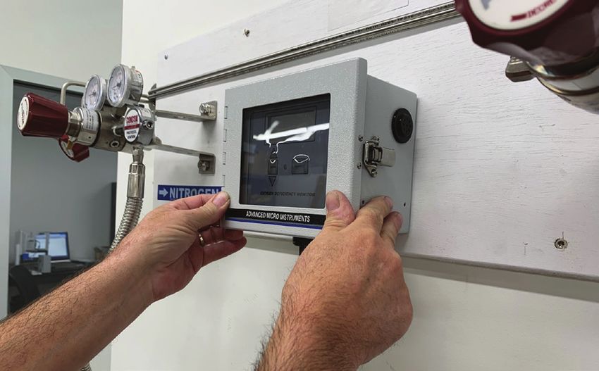
MODEL 221R                           OPERATOR MANUAL

    Special Message from Advanced Micro Instruments (AMI):

      Thank you for purchasing this MODEL 221R for oxygen deficiency monitoring. This
      permanent mount analyzer is designed to alert you and your employees to unsafe oxygen
      levels within an enclosed area. The audible alarm and relay outputs activate when an
      oxygen-depleted or oxygen-rich environment is detected. The unit's special design provides
      exceptional protection while eliminating the frustrations of having to deal with false alarms.

      Note: Read this manual carefully prior to installation.

    TABLE OF CONTENTS
    ANALYZER OVERVIEW                                                                                 2

    METHOD OF MEASUREMENT:                                                                            3

    SAFETY, WARNINGS & CAUTIONS                                                                       4

    ANALYZER INSTALLATION                                                                             5

    ANALYZER OPERATION                                                                                13

    ANALYZER CALIBRATION                                                                              15

    SENSOR REPLACEMENT                                                                                19

    TROUBLESHOOTING/SERVICE19

    ANALYZER ACCESSORIES                                                                              20

    SPECIFICATIONS21

    AMI® WARRANTY                                                                                     23
          LIMITED WARRANTY/DISCLAIMER	                                                                23
          LIMITATION OF LIABILITY	                                                                    23
          LIMITATION OF REMEDIES	                                                                     23

1
ANALYZER OVERVIEW
                                                                                                                           Mounting Hole (x 4)

                    Analyzer                                                                                               LCD Screen
                    Enclosure

                    UP Arrow
                     Button

                    SPAN Button                                                                                           SILENCE Button

                    DOWN Arrow
                      Button

                                                                       (front view)

                                                                                       Protective Earth
                                                                                           Ground

                                                                                                                                           oxygen sensor
                                                                                                                                              location

Electrical Access
       Plate
                                                                                                                                            Name Plate

                      (right side view)                                               (bottom view)                  (left side view)

                                                                                                          I/O Access for Communication

                                                                                                          I/O Access for Power

                                             AVAILABLE CONFIGURATIONS
                                                        (must be specified at time of purchase)
                                                                                                                                 UNIT
                                                UNIT                                UNIT                                   WITH POWER CORD
       BASE UNIT ONLY                     WITH POWER CORD                    WITH REMOTE PROBE                              & REMOTE PROBE
       (PART # 6ANA0600)                   (PART # 6ANA0605)                     (PART # 6ANA0615)                            (PART # 6ANA0610)

                                                                                                                                                           2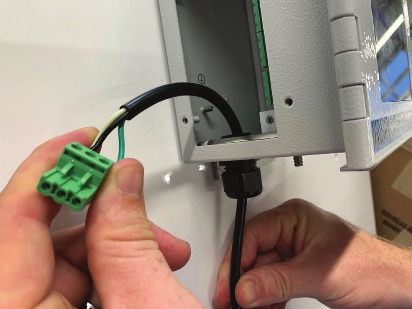
METHOD OF MEASUREMENT:
    ZIRCONIUM OXIDE SENSORS
    The MODEL 221R utilizes zirconium oxide sensors, which provides reliable, accurate percent
    oxygen measurements for a general purpose environment.

    •These sensors have up to a 10-year product life. This eliminates the need to replace sensors every
     6 months and the need to perform monthly calibrations, which drastically lowers maintenance
     costs.

3
SAFETY, WARNINGS & CAUTIONS

        WARNING

Make sure no hazardous gas is present in the area before and during installation.

Violation of the National Electrical Code requirements (especially Article 500 that deals with hazardous areas)
may cause a fire or explosion with the potential for serious injury or loss of life.

        WARNING

You must follow all installation requirements and environmental conditions to avoid protection impairment.

Do not mount the MODEL 221R analyzer in a hazardous area, where explosive gases may be present. The
zirconium oxide sensor will ignite flammable gas mixtures.

A switch or circuit-breaker shall be included in the building installation for the AC power connection. The circuit
breaker should be as close as possible to the unit and within easy reach for the operator. The circuit breaker
should be marked as the disconnecting device for the analyzer.

        CAUTION

You must follow the National Electrical Code (NEC) in your installation.

A supplied IEC power cord must be used if the unit is not to be hard wired. You must follow the National Electrical
Code (NEC) in your installation.

If the unit is hard-wired, the AC wire connecting to the circuit board is made using the three pin Phoenix
combination connector located behind a protective white metal shield.

The Protective Earth Ground Lug on the unit must be connected to the High-Quality Protective Earth Ground using
a16-gauge wire.

                                                                                                                      4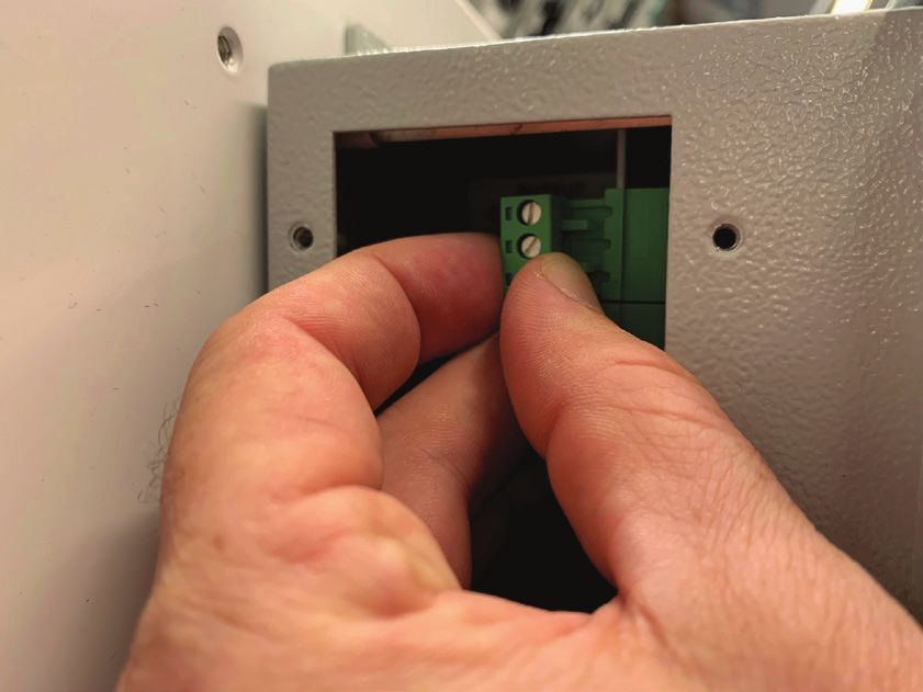
ANALYZER INSTALLATION

    Key Points:
    •It is highly recommended that the Oxygen Deficiency Monitor be installed close to the potential
     leak source, most likely to be the cause of oxygen depletion

    •The zirconium oxide sensor is located on the right side of the box. Make sure that this side is properly
     orientated to the potential source of oxygen depletion.

    •The Oxygen Deficiency Monitor is designed to be mounted in a general-purpose area. Do not install
     it in a hazardous area containing flammable gases.

    •It is recommended that you purchase the optional power cord with your unit. This will allow you to
     unplug and move the unit to an area with fresh ambient air when scheduled calibration needs to be
     performed. Note: The unit is also designed to be hard-wired if that is your preference

    •Analyzer must be connected to a solid ground for the highest level of RFI protection and safety.

    •Use 18 to 16 gauge wire for your electrical connections.

             CAUTION:
             The MODEL 221R is designed for operation between 41°F to 104°F.

             CAUTION:
             The MODEL 221R is designed for monitoring of atmospheric air. Use of the unit to monitor
             process gas will shorten the life of the zirconium oxide sensor and void the warranty.

             CAUTION:
             Ventilation Requirements:
             Install the unit near the area where the oxygen levels need to be monitored. Leave a gap of at
             least 12” around all faces of the unit’s case. (Note: This gap does not include the unit’s backside).

    ANALYZER ENGINEERING DRAWING

5
OPTION 1: INSTALLATION WITH THE POWER CORD

1.    Place the Oxygen Deficiency Monitor at a desired location. It is recommended to position the unit at
      eye-level. Make sure the location is no more than 6 ft from an electrical outlet if the unit has the standard 6-ft
      cord.

2.    Secure the unit to the wall using the 4 mounting holes.

3.    Plug the Power Cord into an AC Power Outlet (The length of the power cord is 6 ft).

OPTION 2: HARD WIRING

1.    Turn off the mains power.

2.    Place the Oxygen Deficiency Monitor at a desired location. It is recommended to position the unit at eye-level.

3.    Secure the unit to the wall using the 4 mounting holes.
                                                                                                                           6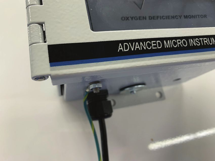
Electrical Access
           Plate

        4.          Remove the Electrical Access Plate on the MODEL 221R to reveal the electrical connections.

        5.          Remove the Access Plug on the bottom side of the MODEL 221R.

        6.          Install a cable gland in the I/O Access for Power. The cable gland should be rated to NEMA 4X (IP65) at the
                    minimum or NEMA 6 (IP68), which is recommended. A cable gland can be acquired from AMI as a separate
                    purchase (Part # 1CON02).

7
7.      Feed cable through the cable gland, which fits Cord OD of 0.24" to 0.47".

8.      Remove the 3-terminal green connector from the terminal strip for easier wiring.

9.      Make the following electrical connections to the proper positions on the Phoenix connector.

        – Connect the fused line side of a 90 —240 VAC power source to the H terminal
        – Connect the neutral from the power source to the N terminal
        – Connect the shield ground to a good earth ground or equivalent.

IMPORTANT: When attaching wiring to the green terminal connectors, use either solid wire or
		         stranded wire with wire ferrule(s) attached. Verify no loose strands are visible after
		         installation of wire ferrule(s).

10.     Re-install the 3-terminal green connector firmly back in its place in the terminal strip.

                                                                                                       8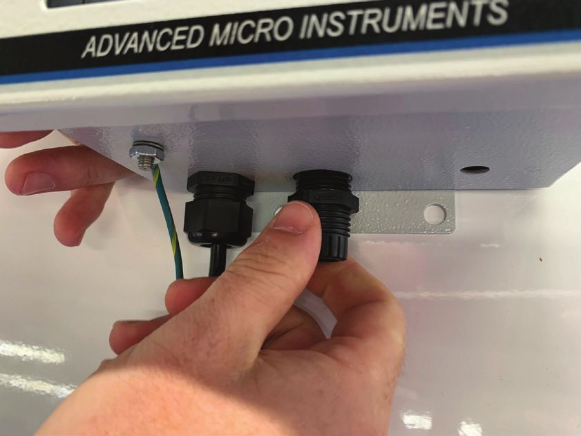
HARD WIRING FOR RS485 COMMUNICATIONS, 4–20mA, AND ALARM RELAYS

    Follow the next several steps to wire RS485 Communications, 4–20 mA or Alarm Relays. If you do not wish to include
    any of these in your installation, skip this section and proceed to Step 14.

                                                         Metal Hole Plug

    11.      Remove the Metal Hole Plug.

    12.      Install a cable gland to the I/O Access for Communication. The cable gland should be rated to NEMA 4X
             (IP65) at the minimum or NEMA 6 (IP68), which is recommended. A cable gland can be acquired from AMI
             as a separate purchase (Part # 1CON02).

    13.      Feed cable through the cable gland.

9
14. Remove the approprate 3-terminal green connector that corresponds to your target wiring.
15. Make the following electrical connections to the proper positions on a Phoenix connector.
– Connect the fused line side of a 90 —240 VAC power source to the H terminal
– Connect the neutral from the power source to the N terminal
– Connect the shield ground to a good earth ground or equivalent.
16. Connect the Phoenix connector to the appropriate Interface Group.
LIST OF INTERFACE GROUP & CORRESPONDING CONNECTION
INTERFACE GROUP CONNECTION
1st Interface Group RS485 Communications
2nd Interface Group 4–20mA Analog Output
3rd Interface Group Alarm One Relays
4th Interface Group Alarm Two Relays
Note: The RS485 cable, which has a length of ~ 6 ft (1.8 m), must be purchased
separately from AMI (Part # 3DON01).
To complete wiring for another connection, repeat Steps 12 & 13 and select a different connection to install the
Phoenix connector.
1017. Put the Electrical Access Plate back in place and secure.
Earth Ground
18. Connect the shield ground to a good earth ground or equivalent.
19. Turn on the mains power.
11INSTALLATION WITH REMOTE PROBE (OPTIONAL)
PROBE & BRACKET ENGINEERING DRAWING
Customers that ordered the MODEL 221R with Remote Probe can mount the Probe using the included bracket as
shown above.
Note: The probe includes a 12-ft cable but can be ordered with a longer, optional length up to 300 ft. To extend the
cord to a different length, contact the factory.
12ANALYZER OPERATION
Front Panel Interface
LCD Screen
UP Arrow Button
SILENCE Button
LED indicator
DOWN
Arrow Button
What are the Alarm Conditions and the LED Warnings?
AUDIBLE
INDICATION LED COLOR ALARM RELAYS
Below 19.5% Oxygen Solid Red 95 dB ON Relay 1 de-energized, Relay 2 de-energized
DANGER Level Warning Light
Above 23.5% Oxygen Solid Red 95 dB ON Relay 1 de-energized, Relay 2 de-energized
ENRICHED Level Warning Light
Below 20.0% Oxygen Solid Yellow OFF Relay 1 de-energized, Relay 2 energized
CAUTION Level Caution Light
Safe Oxygen Levels Solid Green Light OFF Relay 1 energized, Relay 2 energized
Normal Level
Note: The Common Contact (C) and Normally-Close Contact (NC) will close whenever an alarm is triggered.
If the unit detects oxygen levels less than 20%, the LED on the front panel will change from green to yellow.
If it detects oxygen level below 19.5% (OSHA standard), the LED will change to red, and the audible alarm will sound to alert
personnel to leave the room. The audible alarm is rated at 95dB.
If oxygen levels exceed 23.5%, the audible alarm will sound.
WARNING:
If the alarm is triggered for 19.5% oxygen levels, LEAVE THE AREA IMMEDIATELY!
13POWER STATUS LED COLOR ACTIVITY
Unit Warming-up Solid Blue Light Alarms are disabled.
Lost of AC Power,
Flashing Red No audible alarm, and Relay 1 and Relay 2 perform as normal.
Back-up Battery Power
Warning Light
Running
After ~45 min of Back-up Flashing Red Audible Alarms Trigger, no LCD Reading,
Battery Power Use Warning Light Relay 1 and Relay 2 de-energize.
What happens when there is a blackout or loss of AC power to
the unit?
The MODEL 221R has a battery back-up. If the AC power fails, the internal batteries will keep the unit operational
for about 1 hour. During this time, the LED backlight on the LCD panel will flash, and the status LED will turn red and
flash. After 45 min of running on back-up battery power, the audible alarm will trigger. And after about 1 hour of
total time running on back-up battery power, the batteries will start to die, and the LCD back light will turn off though
the LED will continue to flash.
How do I silence the alarm?
SILENCE Button
Press the SILENCE button on the front panel. The Monitor will remain silent for the amount of time set in the
System. The default setting is 1 minute.
14ANALYZER CALIBRATION
Note: The MODEL 221R Oxygen Deficiency Monitor has been calibrated at the factory at an atmosphere at
sea level and is ready for use. It should be re-calibrated again if the new unit is installed at a different elevation than
at sea level.
AMI recommends to calibrate the unit once a year.
There are 2 methods for calibration:
•Calibration with Air
or
•Calibration with a Span Gas
CALIBRATION WITH AIR
For this option, you will need to remove the Oxygen Deficiency Monitor from where it is currently installed and take it
to a location where there is fresh ambient air. This will ensure that no contaminant will interfere with the calibration.
Note: Once the Monitor is disconnected from the AC power source, its battery will continue to supply 1 hour of back-
up power.
1. Once in an area with fresh ambient air, the oxygen level reading should stabilize rather quickly.
Up
Arrow Buttons Span
Down Button
Arrow Buttons
2. Verify that the Oxygen Deficiency Monitor is reading 20.9%. If not, press the SPAN button and, within
3 seconds, use the UP or DOWN arrow buttons to adjust the LCD reading to 20.9%.
Note: Unlike AMI's other Analyzers, the display on this unit WILL NOT blink when the SPAN
button is pressed.
3. Return the MODEL 221R back to its location, reinstall it and reconnect it to power.
15CALIBRATION WITH A SPAN GAS
We encourage you to view our calibration video at www.amio2.com before starting.
REQUIRED COMPONENTS:
• Certified oxygen span gas with a nitrogen background
Note: AMI recommends a percent oxygen span gas between 10 to 20% with the balance being
nitrogen.
• Calibration adapter - Part Number 4BLK41 (sold separately by AMI)
• Stainless steel or brass body pressure reducing regulator, outfitted with inlet/outlet pressure
gauges and CGA-580 connection fitting (note: regulator must have a stainles steel diaphragm)
• Tank wrench
IMPORTANT:
• The Block and Bleed procedure is required only when a regulator has been connected to a gas
cylinder for the first time or has not been used for an extended period of time
• The Block and Bleed procedure will clear any trapped oxygen from the regulator and insure
an accurate calibration.
'BLOCK AND BLEED' STEPS
1. Connect a pressure reducing regulator to the Span Gas Tank.
Note: It is essential that the regulator has a stainless-steel diaphragm. Failure to do so will
invalidate the calibration.
2. After the regulator has been attached to the Span Gas Tank and properly tightened, 'Block and
Bleed' the High Pressure side of the Span Gas Regulator following this procedure:
Quickly open the valve of the Span Gas Tank approximately ~½ turn. Confirm the inlet pressure
gauge responds to 'full tank pressure'. Then, quickly close the valve of the Span Gas Tank.
Loosen the regulator nut that connects the regulator to the Span Gas Tank approximately ¼ turn
using a wrench until the inlet pressure gauge drops to zero, and then quickly tighten the regulator
nut to the Span Gas Tank.
Repeat the above procedure 7 times.
16Calibration
Adapter
3. Connect the Calibration Adapter to the Analyzer and then connect non-diffusive flexible tubing
from the regulator to the Calibration Adapter.
Note: You CANNOT use Teflon® or another plastic tubing for this step as it would allow oxygen
from the air to diffuse into the Span Gas Stream and invalidate your calibration.
4. Now, 'Block and Bleed' the Low Pressure side of the Regulator:
Connect the flexible tubing to the Calibrator Adapter of the Analyzer so gas can escape during
the 'Block & Bleed' process.
Open the valve of the Span Gas Tank approximately ½ turn. Confirm the high-pressure and low
pressure gauges respond. Then, quickly close the valve of the Span Gas Tank.
Note: The gas will escape at the Span Gas Inlet Port since it is not fully sealed connection.
Repeat this procedure 7 times - but tighten the gas fitting at the Span Gas Inlet Port for the last
'Block & Bleed'
CALIBRATION STEPS
1. Connect the Calibration Adapter to the MODEL 221R.
2. Open the valve of the Span Gas Tank and adjust the regulator pressure to approximately 20 psig.
3. Allow a brief moment for the measurment reading to stabilize.
4. If the Span Gas used is outside the alarm settings and causes an alarm to trigger, press the
SILENCE Button to quiet the alarm. This will last for 60 seconds (by default). If it takes longer than
60 seconds to complete the calibration, the SILENCE Button will need to be pushed again to quiet
the alarm for another 60 seconds.
175. Span the Analyzer to the value of the oxygen, specified on the Span Gas Tank, by doing the
following:
Up
Arrow Buttons Span
Down Button
Arrow Buttons
Press the SPAN Button and release, and, within 3 seconds, use the UP or DOWN arrow buttons to adjust
the LCD reading to the value stated on your calibration gas cylinder.
The calibration is now completed.
How do I view the current calibration Span Factor?
UP Arrow Button
Press the UP Arrow Button.
IMPORTANT:
The SPAN FACTOR is an indication of sensor life. The span factor is accurate only after an accurate
callibration has been completed.
The SPAN FACTOR of a new oxygen sensor is in the range of 400 to 600.
After each calibration, the SPAN FACTOR will increase slightly. When the SPAN FACTOR reaches around
980, the sensor is nearing the end of its useful life. Contact AMI to return your unit for sensor replacement.
18How do I view the Last Calibration Date?
DOWN Arrow Button
Press the DOWN Arrow Button to view the last date in 'month.year' (mm.yy) format.
SENSOR REPLACEMENT
The MODEL 221R is shipped from our factory with the zirconium oxide sensor already installed inside the
Oxygen Defiiciency Monitor.
The zirconium oxide sensor has a product life up to10 years.
To replace the sensor near the end of its product life, contact AMI to make arrangements. The sensor can only
be replaced on the MODEL 221R at our factory.
TROUBLESHOOTING/SERVICE
The MODEL 221R has no serviceable parts inside. If you encounter an issue with your unit, contact AMI for
support and to obtain a Return Material Authorization (RMA).
19ANALYZER ACCESSORIES
There are several accessories available for purchase for the MODEL 221R.
Accessories Part Number
Calibration Adapter 4BLK41
Cable Gland for I/O Access for Power, 1CON02
for Cord OD 0.24" to 0.47"
RS485 cable with length ~ 6 ft (1.8 m) 3DON01
20SPECIFICATIONS
USAGE
Both indoor and outdoor use
Max Altitude _________________________________________________________________________ 15,000 ft
Relative Humidity_____________________________Maximum relative humidity is 80% for temperatures up to 88°F,
This maximum relative humidity decreases linearly to 50% relative humidity at 104°F.
Ingress Protection____________________________________________________________Designed to meet IP44
Pollution degree: 2 (Only non-conductive pollution occurs except that occasionally a temporary conductivity caused
by condensation is to be expected).
PHYSICAL
Dimensions ______________________________________________________________ 7.0”W x 5.7”H x 4.5”D
Weather-tight 4X package
Weight ______________________________________________________________________________ 4.0 lbs
Digital Display ________________________________________ 4–digit LCD (reads full scale from 0.0% to 25.0%)
Mounting __________________________________________________________________________Wall mount
Gas Connections ______________________________Diffusion screen. No pump, sample tubing or fittings required
TECHNOLOGY
Method of Measurement ___________________________ Zirconium Oxide Sensor (up to10-year life expectancy)
PERFORMANCE
Low Minimum Detection Threshold __________________________________________________ 0.05% of oxygen
Response Time ______________________90% full scale response times for specified range:AREA CLASSIFICATION
Area Classification ______________________________ Approved to meet General Purpose UL 61010-1 Standard
and IP 65 Requirements.
CE Marked
OPTIONS
Probe ________________________________________ Optional Remote Oxygen Sensing Probe
(can be located up to 300 ft away from the control unit)
POWER
Requirements _________________________________________________________90-240VAC 50/60Hz (11W)
Mains supply voltage fluctuations up to +/-10% of the nominal voltage
Battery back-up _________________________________________________________________________1 hour
22AMI® WARRANTY
LIMITED WARRANTY/DISCLAIMER
The warranty period is TWO YEARS for the Analyzer. Any failure of material or workmanship will
be repaired free of charge for that specified period from the original purchase (shipping date) of
the instrument. AMI will also pay for 1-way ground shipment back to the customer.
The warranty period for the oxygen sensor is 6 months.
Any indication of abuse or tampering of the instrument will void the warranty.
Receiving the Analyzer
When you receive the instrument, check the package for evidence of damage and if any is found
contact the shipper. Although every effort has been made to assure that the Analyzer meets all
performance specifications, AMI takes no responsibility for any losses incurred by reason of the
failure of this analyzer or associated components. AMI's obligation is expressly limited to the
Analyzer itself.
EXCEPT FOR THE FOREGOING LIMITED WARRANTY, AMI MAKES NO WARRANTIES, EXPRESS,
IMPLIED OR STATUTORY, AS TO THE NON-INFRINGEMENT OF THIRD-PARTY RIGHTS,
MERCHANTABILITY, OR FITNESS FOR A PARTICULAR PURPOSE. IF APPICABLE LAW REQUIRES
ANY WARRANTIES WITH RESPECT TO THE SYSTEM, ALL SUCH WARRANTIES ARE LIMITED IN
DURATION TO TWO (2) YEARS FROM THE DATE OF DELIVERY.
LIMITATION OF LIABILITY
IN NO EVENT WILL AMI BE LIABLE TO YOU FOR ANY SPECIAL DAMAGES, INCLUDING ANY
LOST PROFITS, LOST SAVINGS, OR OTHER INCIDENTAL OR CONSEQUENTIAL DAMAGES,
EVEN IF THE COMPANY HAS BEEN ADVISED OF THE POSSIBILITY OF SUCH DAMAGES, OR
FOR ANY CLAIM BY ANY OTHER PARTY.
LIMITATION OF REMEDIES
AMI's entire liability and your exclusive remedy under the Limited Warranty (see above) shall be
the replacement of any Analyzer that is returned to the Company and does not meet the Company's
Limited Warranty.
23PAGE INTENTIONALLY LEFT BLANK
24HIGH PERFORMANCE RELIABILITY INTUITIVE DESIGN
www.amio2.com ADDRESS:
Advanced Micro Instruments, Inc.
Tel 714.848.5533 225 Paularino Avenue
Fax 714.848.4545 Costa Mesa, CA 92626
Email sales@amio2.com
OM-300-006 Rev D
01/12/2022
© Advanced Micro Instruments, Inc.You can also read