Momo motion - Instructions for use. momo motion. The tried-and-tested tricycle with E-drive - Atlas Kidtech
←
→
Page content transcription
If your browser does not render page correctly, please read the page content below
momo motion.

Instructions for use.
momo motion. The tried-and-tested tricycle with E-drive.

Many thanks.

Dear Customer
At this point we would like to thank you for placing your trust in our company and for
purchasing our product. We ask you to read through the Instructions for use carefully
prior to initial commissioning of the product, and to observe them. Please note that
guidelines and representations in these Instructions for use may deviate from your pro-
duct due to differing equipment. We reserve the right to make technical modifications.

Important information!
Ensure that these Instructions for use remain with the product.

Your schuchmann Team
03   Contents.
     1. Preparation. ���������������������������������������������������������������������������������� 05
         1.1 Delivery������������������������������������������������������������������������������������������������������������������������������05
         1.2 Safety measures prior to use���������������������������������������������������������������������������������05
         1.3 Safe disposal�����������������������������������������������������������������������������������������������������������������05
              1.3.1 Packaging��������������������������������������������������������������������������������������������������������������05
              1.3.2 Product�������������������������������������������������������������������������������������������������������������������05
         1.4 Where to store the Instructions for use�������������������������������������������������������������05
     2. Product description. ���������������������������������������������������������������������� 06
         2.1 General information���������������������������������������������������������������������������������������������������� 06
         2.2 Handling and transport�������������������������������������������������������������������������������������������06
         2.3 Application areas, use according to the intended purpose����������������06
         2.4 Use not in accordance with the intended purpose / warning guide-
         lines��������������������������������������������������������������������������������������������������������������������������������������������08
         2.5 Equipment for basic model������������������������������������������������������������������������������������09
         2.6 Product overview��������������������������������������������������������������������������������������������������������09
         2.7 Overview of equipment / accessories��������������������������������������������������������������10
         2.8 Drive possibilities���������������������������������������������������������������������������������������������������������� 15
         2.9 E-drive������������������������������������������������������������������������������������������������������������������������������� 16
         2.10 Light system�������������������������������������������������������������������������������������������������������������������17
     3. Settings. ��������������������������������������������������������������������������������������� 18
         3.1 Presettings������������������������������������������������������������������������������������������������������������������������ 18
             3.1.1 Handlebar adjustment������������������������������������������������������������������������������������ 18
             3.1.2 Saddle adjustment������������������������������������������������������������������������������������������� 19
         3.2 Brakes�������������������������������������������������������������������������������������������������������������������������������� 20
             3.2.1 Parking brake������������������������������������������������������������������������������������������������������ 20
             3.2.5 Backpedal brake����������������������������������������������������������������������������������������������� 21
         3.3 Tyres and hoses������������������������������������������������������������������������������������������������������������ 21
         3.4 Chains and chain maintenance�������������������������������������������������������������������������� 21
     4. Accessories. ���������������������������������������������������������������������������������� 22
         4.1 Dynamic back and pelvic guide pelotte pads���������������������������������������������22
             4.1.1 Width adjustable back and pelvic guide pelotte pads�����������������22
         4.2 Headrest���������������������������������������������������������������������������������������������������������������������������22
         4.3 Push bar����������������������������������������������������������������������������������������������������������������������������23
         4.4 Brake for accompanying escorts������������������������������������������������������������������������23
         4.5 Handlebar lock limiter�����������������������������������������������������������������������������������������������23
         4.6 Holding bracket with mount���������������������������������������������������������������������������������� 24
         4.7 Universal mount����������������������������������������������������������������������������������������������������������� 24
         4.8 Crank shortener (continuously adjustable)�����������������������������������������������������25
         4.9 Crank shortener������������������������������������������������������������������������������������������������������������25
         4.10 Special crank for knee contracture������������������������������������������������������������������25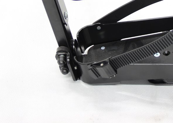
04   Contents.
     5. Foot positioner. ���������������������������������������������������������������������������� 26
         5.1 Exercise bike pedals����������������������������������������������������������������������������������������������������26
         5.2 Foot fixation pedals����������������������������������������������������������������������������������������������������26
         5.3 Foot pans�������������������������������������������������������������������������������������������������������������������������26
         5.4 Foot pans with leg guidance��������������������������������������������������������������������������������27
         5.5 Foot pans with dynamic leg guidance�������������������������������������������������������������27
     6. Strap systems. ������������������������������������������������������������������������������ 28
         6.1 Chest strap���������������������������������������������������������������������������������������������������������������������� 28
         6.2 Positioning vest������������������������������������������������������������������������������������������������������������ 28
         6.3 Groin harness, T-shaped������������������������������������������������������������������������������������������29
         6.4 4-point pelvic harness����������������������������������������������������������������������������������������������29
         6.5 Manual fixation�������������������������������������������������������������������������������������������������������������29
     7. Repairs and cleaning. �������������������������������������������������������������������� 30
         7.1 Care and maintenance���������������������������������������������������������������������������������������������30
         7.2 Repairs�������������������������������������������������������������������������������������������������������������������������������� 31
         7.3 Spare parts����������������������������������������������������������������������������������������������������������������������32
         7.4 Duration of use and re-use�������������������������������������������������������������������������������������32
         7.5 Torque information�������������������������������������������������������������������������������������������������������32
     8. Technical data. ������������������������������������������������������������������������������ 33
     9. Guarantee. ������������������������������������������������������������������������������������ 33
     10. Identification. ����������������������������������������������������������������������������� 34
         10.1 EC declaration of conformity������������������������������������������������������������������������������� 34
         10.2 Serial number / date of manufacture������������������������������������������������������������ 35
         10.3 Product version���������������������������������������������������������������������������������������������������������� 35
         10.4 Issue of the document������������������������������������������������������������������������������������������� 35
         10.5 Name and address of the manufacturer, specialist dealer supplying
         the product �������������������������������������������������������������������������������������������������������������������������� 35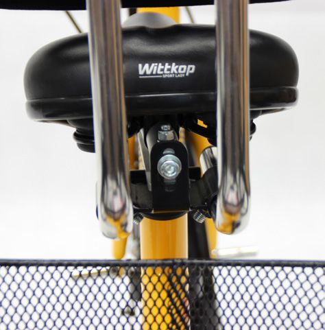
05   1. Preparation.
     1.1 Delivery
     On receiving the product, please check it for completeness, lack of faults
     and any transport damage. Check the goods in the presence of the deli-
     vering company. Should transport damage have occurred, please arrange
     for an inventory (determination of the faults) to be made in the presence of
     the forwarder. Please send a complaint in writing to the specialist dealer
     responsible.

     1.2 Safety measures prior to use
     Correct usage of the tricycle requires precise and careful
     training of the accompanying person. We ask you to read through the
     Instructions for use carefully prior to initial commissioning of the
     tricycle, and to observe them. Cushioned parts may become warm when
     exposed to direct sunlight. Cover these parts or protect the equipment from
     direct sunlight.

     1.3 Safe disposal
     In order to preserve and protect the environment, to prevent
     environmental pollution and to improve the recycling of raw materials, plea-
     se note the disposal instructions in points 1.3.1 and 1.3.2.

     1.3.1 Packaging
     The product packaging should be stored in case the product needs
     to be transported again. Should you have to return the product for
     repairs or in case of a guarantee claim, please if possible use the
     original box so that the product is optimally packaged.
     Separate the packaging materials for recycling according to their classifi-
     cation. Do not leave packaging materials unattended, as they are a pos-
     sible source of danger.

     1.3.2 Product
     Separate the raw materials used in the product for recycling
     according to their classification (see material information under Point 2.1).

     1.4 Where to store the Instructions for use
     Please store these Instructions for use carefully and ensure that these Inst-
     ructions for use remain with the product in case of re-use.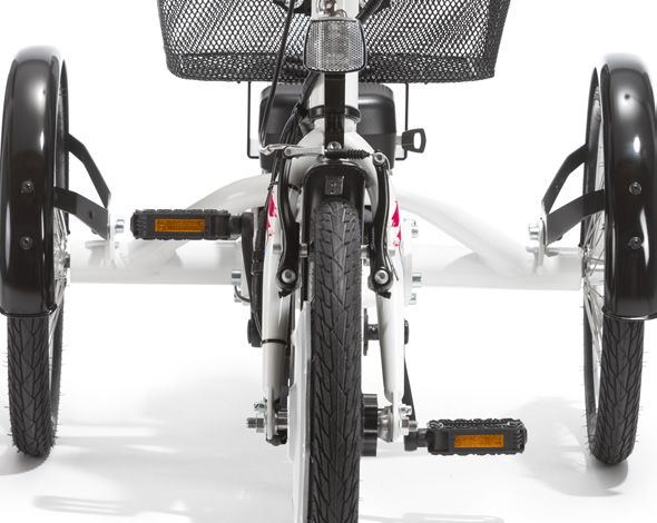
06 2. Product description.
2.1 General information
All base frames are made of aluminium, which is non-corroding and
powder-coated. All other materials used are protected against corrosion
through the use of stainless steel, aluminium or plastic. All important parts,
such as the saddle, handlebars or also the pedals, can be individually
adapted to the individual requirements. The special accessories allow
children and teenagers to be positioned for example around the upper body
or in the lower leg / foot area. The tricycles generally have a brake hub /
backpedal hub brake on the rear wheel (except for those with a rigid
sprocket) and an air pressure-independent parking brake on the front wheel.
2.2 Handling and transport
The momo motion. is not designed to be carried, as it is fitted with tyres.
Should you have to carry the equipment due to obstacles, ensure that all
moving parts are tightened. Then two people should position themselves
next to the tricycle, grip it on the left and right of the frame and carry it
to the required location. To transport the tricycle, reduce all adjustments
to their most compact size (saddle height, handlebar height, remove
accessories etc.).
2.3 Application areas, use according to the intended purpose
Indications
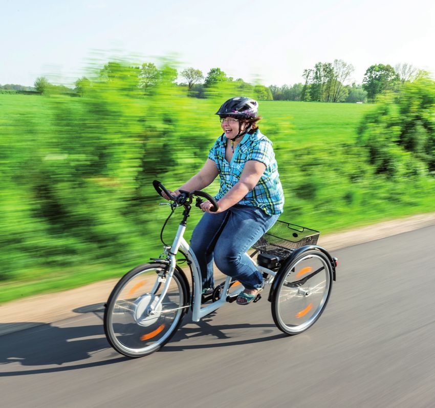
The momo motion. is suitable for children and adolescents with neuromuscular
(neurological, orthopaedic and neurodegenerative) disorders (such as
cerebral palsy and muscular dysplasia and atrophy, rheumatism) as well as
cardiovascular diseases and chromosomal abnormalities associated with
hypotension. Due to their motor limitations (reduced muscle strength and
endurance, cardio-respiratory limitations, joint mobility limitations, etc.), these
patients have limited use of foot pedal-operated tricycles.
The momo motion. is used to support physiotherapeutic treatment, the trai-
ning of balance reactions and movement coordination (alternating leg mo-
vements, eye-hand coordination, training isolated arm and leg movements).
The function of start-up assistance is particularly important.
It is also used for the specific development of muscle strength and enduran-
ce (with appropriate indication also for avoiding overloading of the muscles
with simultaneous function preservation). The mobility of the joints is suppor-
ted and the restrictions are counteracted by insufficient cardio-respiratory
function of the patients. The function of residual power support is hereby
emphasised.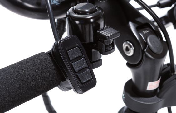
07   2. Product description.
     Contraindications
     In general, the indications for riding a bicycle should be approved by a doctor
     or orthopedist. It should therefore be clarified prior to procurement whether
     contraindications exist for the patient. In general, any type of pain repre-
     sents a contraindication.

     For roadworthy tricycles, the following components are specified in accor-
     dance with the German Road Traffic Regulations:
     • Two brakes functioning independently of one another
     • A bicycle bell with a clear ring
     • Headlamps, rear lamp with reflectors, large-area reflectors, pedal
       reflectors, 2 yellow spoke reflectors or white reflecting rings on each
       wheel, and front reflectors in the design tested for the construction type.
     • A bicycle trailer may only be used on bicycles with a sturdy frame and
       fork construction. Also important are strong bicycle brakes at the front
       and rear. Users must remember that the riding characteristics of the
       loaded trailer change substantially in comparison to operation of the
       bicycle on its own.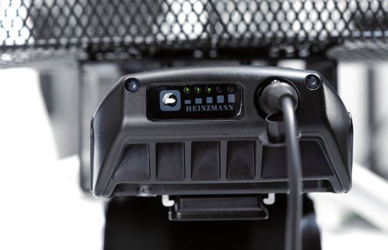
08   2. Product description.
     2.4 Use not in accordance with the intended purpose / warning guidelines
     • Only ride if the bicycle is in proper condition!
     • Correct usage of the product requires precise and careful training of
        the accompanying person.
     • Replace bent handlebars and handlebar stems immediately!
     • Continued use or repair means a risk of breakages.
     • The vehicle may only be used on stable and flat ground.
     • Please observe the "Technical data" in these instructions for use for the
        maximum permitted patient weight.
     • Always wear light-coloured and distinctive clothing!
     • Always be ready to brake, in particular in steep terrain and sections
        which are not easy to assess!
     • Show consideration for other people who are walking or hiking!
     • Do not hang loads on the handlebars; this compromises the travel
        safety.
     • Test the fastenings for the pedal cranks, pedals and, if applicable, the
        wheels regularly
     • For your own safety, we recommend that you always use your vehicle
        with a helmet. Please ensure in particular that the helmet is of good
        quality. It should accord at least with the legal regulations or
        recommendations (standard: EN 1078 or ANS)!
     • Check that the brakes, lights and bell function properly prior to each
        journey!
     • Secured screws must not be loosened, otherwise the guarantee is lost.
     • Ensure that your vehicle accords with the legal requirements!
     • Do not use headphones, for example, so that you can remain aware of
        warning sounds.
     • If a push bar is mounted, this may only be used to guide the bicycle.
        The push bar is NOT suitable for moving, lifting or tilting the bicycle!
     • In wet conditions, the braking distance of your bicycle will become
        longer. Therefore, always ensure that your speed remains such that you
        can stop at any time.
     • The tricycles are not suitable for carrying a second person. The
        consequences arising from such a use shall not fall within the
        scope of responsibility of the manufacturer.
     • The bicycle basket may only bear loads of up to 20 kg.
     • When adjusting the tricycle there is the risk of trapping
        or crushing limbs.
     • Users who have difficulty reading must have someone read these
        Instructions for use aloud so that they understand how to use
        the product.
09   2. Product description.
     2.5 Equipment for basic model
     • with Heinzmann Direct Power        • Angle adjustable handlebar stem
       Motor (36V, 250W, impulse torque   • Handlebar damper for stabilisati-
       60Nm)                                on when moving straight on
     • Aluminium frame with extra-low     • Lighting system according to StV-
       access point                         Zo, which is powered by the Li-ion
     • Rim brake with separate parking      high-power battery (11Ah)
       brake                              • incl. mudguards and basket

     2.6 Product overview
     The Fig. below is intended to show you the designation of the most
     important components as well as the terms which you will find in these
     Instructions for use.

                                                                    T-saddle post

     Dynamic                                                          Gear system
     Back pelotte pad
                                                               Display for E-drive

                                                                       Handlebars
     Holding bracket
                                                                 Angle adjustable
                                                                  handlebar stem
     Saddle
                                                            Lever for parking brake

     Basket
                                                                          V-brake

     Mudguard

     Battery for E-drive
                                                                           E-drive

                           Pedal
                                                           Aluminium frame with
                                                           extra-low access point
10   2. Product description.
     2.7 Overview of equipment / accessories
                                       DirectPower E-drive from Heinzmann

     The new momo motion. is equipped with the DirectPower E-drive from Heinzmann. This allows us to offer you
     a wear-free and silent direct drive. The motor is designed to be brushless and without gears. This minimises
     maintenance and wear and eliminates motor noise. The recuperative system automatically recharges when
     driving downhill or braking. This means that the range can be increased by up to 15 %. The existing force of
     the user is measured by a force sensor integrated in the bottom bracket, and the assistance from the electric
     drive is adjusted.
     Choose the suitable E-drive for the momo motion. from the following configurations. You can choose whether
     the drive should be equipped with or without start-up assistance. In addition, you can choose between a
     beginner version and an advanced version. The difference here is the start-up and the top speed of the
     various modes Eco, Standard and Power, which can be selected via the display. An analysis cable can be used
     to change the selected version at a later date.

     DirectPower E-drive from Heinzmann – without start-up assistance

       for                                                             Start-up handling / top speed
             Revision
      size                                              Eco                       Standard                  Power
             Beginner           (36 02 070)      gentle / 4 km/h              medium / 4 km/h          strong / 6 km/h
       16“
             Advanced           (36 02 071)     medium / 6 km/h                strong / 8 km/h        strong / 10 km/h
             Beginner           (36 03 070)      gentle / 4 km/h              medium / 4 km/h          strong / 6 km/h
      20“
             Advanced           (36 03 071)     medium / 6 km/h                strong / 8 km/h         strong / 12 km/h
             Beginner           (36 04 070)      gentle / 6 km/h              medium / 8 km/h          strong / 12 km/h
      24“
             Advanced           (36 04 071)      gentle / 10 km/h             medium / 15 km/h        strong / 20 km/h
             Beginner           (36 05 070)      gentle / 6 km/h              medium / 8 km/h          strong / 12 km/h
      26“
             Advanced           (36 05 071)      gentle / 10 km/h             medium / 15 km/h        strong / 20 km/h

     DirectPower E-drive from Heinzmann – with start-up assistance

     Select whether the start-up assistance should          Fig. 1                           Fig. 2
     be activated by pressing the button (Fig. 1) or
     by twist handle (Fig. 2)

                                                                                     Start-up handling / top speed
       for
             Revision
      size                                                       Start-up
                                                                                    Eco          Standard       Power
                                                                assistance
             Beginner with twist handle       (36 02 072)                         mild /         medium /      strong /
                                                                     4 km/h
             Beginner with button             (36 02 073)                         4 km/h          4 km/h        6 km/h
       16“
             Advanced with twist handle       (36 02 074)                        medium /        strong /      strong /
                                                                     6 km/h
             Advanced with twist handle       (36 02 075)                         6 km/h          8 km/h       10 km/h
             Beginner with twist handle       (36 03 072)                         mild /         medium /      strong /
                                                                     4 km/h
             Beginner with button             (36 03 073)                         4 km/h          4 km/h        6 km/h
      20“
             Advanced with twist handle       (36 03 074)                        medium /        strong /      strong /
                                                                     6 km/h
             Advanced with twist handle       (36 03 075)                         6 km/h          8 km/h       12 km/h
             Beginner with twist handle       (36 04 072)                         mild /         medium /      strong /
                                                                     6 km/h
             Beginner with button             (36 04 073)                         6 km/h          8 km/h       12 km/h
      24“
             Advanced with twist handle       (36 04 074)                          mild /        medium /      strong /
                                                                     6 km/h
             Advanced with twist handle       (36 04 075)                         10 km/h         15 km/h      20 km/h
             Beginner with twist handle       (36 05 072)                         mild /         medium /      strong /
                                                                     6 km/h
             Beginner with button             (36 05 073)                         6 km/h          8 km/h       12 km/h
      26“
             Advanced with twist handle       (36 05 074)                          mild /        medium /      strong /
                                                                     6 km/h
             Advanced with twist handle       (36 05 075)                         10 km/h         15 km/h      20 km/h
11 2. Product description.
Saddle
Art. No. Saddle Width Length
37 01 001 Standard saddle Size 1 15 cm 21 cm
37 02 001 Standard saddle Size 2 15 cm 24 cm
37 03 001 Standard saddle Size 3 18 cm 26 cm
Art. No. Saddle Rear width Front width Length
37 01 024 Gel saddle Size 1 19 cm 4 cm 24 cm
37 02 024 Gel saddle Size 2 24 cm 7 cm 27 cm
Length
Art. No. Saddle Rear width Front width Rear length
total
Saddle seat with ischium
37 01 003 20.5 cm 4 cm 9.5 cm 14.5 cm
depressions Size 1
Saddle seat with ischium
37 02 003 24 cm 4 cm 9.5 cm 14.5 cm
depressions Size 2
Art. No. Saddle Rear width Width in centre Front width Length
Unicycle saddle –
Banana-shaped
37 00 010 11 cm 6 cm 8 cm 25 cm
(Step length increases
by 2 cm)
Length
Art. No. Saddle Rear width Front width Rear length
total
Moped saddle (Inside
37 00 023 leg length increases 26 cm 9.5 cm 12 cm 25 cm
by 2 cm)
Saddle posts
Art. No. Saddle post
37 02 004 Standard saddle post Size 2 for 16"
37 03 004 Standard saddle post Size 3 for 20" - 26"
Art. No. T-saddle post
37 02 005 T-saddle post Size 1 for 12"
37 03 005 T-saddle post Size 3 for 24" + 26"
Holding bracket
Art. No. Holding bracket with mount Max. height* Depth
37 01 007 Holder bracket Size 1 20 cm 12 cm
37 02 007 Holder bracket Size 2 30 cm 12 cm
37 03 007 Holder bracket Size 3 37 cm 12 cm
37 04 007 Holder bracket Size 4 53 cm 12 cm
37 09 007 Holder bracket, customer-made ___ cm ___ cm
Universal bracket – for harnesses when not using
37 02 055
pelotte pads (width = 27.5 cm)
* Max. height: *Measured on a standard saddle up to the top edge of the back pelotte pad12 2. Product description.
Headrest
Art. No. Headrest Width Height
37 01 029 Headrest Size 1 20 cm 15 cm
37 02 029 Headrest Size 2 23 cm 18 cm
Handlebars
Art. No. Classic handlebars – black Width
37 02 011 Classic handlebars for 16" 50 cm
37 03 011 Classic handlebars for 20" 58 cm
37 04 011 Classic handlebars for 24"-26" 61 cm
Art. No. Touring handlebars Width Depth
37 01 012 Touring handlebars Size 1 55 cm 17 cm
37 02 012 Touring handlebars Size 2 58 cm 17 cm
Art. No. Round handlebars Width Depth
37 01 013 Round handlebars Size 1 40 cm 17 cm
37 02 013 Round handlebars Size 2 43 cm 25 cm
Art. No. Multifunctional handlebars – suitable for 20" – 26" Width Depth
37 02 014 Multifunctional handlebars 61.5 cm 16.5 cm
Art. No. Handlebar lock limiter – adjustable up to direction determination
37 03 006 Handlebar lock limiter Size 2 for 16" - 26"
Art. No. Handlebar extension Length
37 02 022 Handlebar extension Size 2 for 16" - 26" 10 cm
Foot pans
Min. Max.
Foot pans Min. Max. Min. Max.
height height
Art. No. with leg width at Front width at Rear Length
of leg of leg
guidance front width rear width
guidance guidance
37 01 018 Size 1 8.7 cm 10.4 cm 5.7 cm 7.4 cm 17.4 cm 15 cm 18.5 cm
37 02 018 Size 2 9.5 cm 12 cm 6.7 cm 9.2 cm 20.1 cm 18 cm 22 cm
37 03 018 Size 3 11.5 cm 14 cm 8.1 cm 10.6 cm 23.8 cm 21 cm 26 cm
37 04 018 Size 4 11.5 cm 14 cm 8.1 cm 10.6 cm 23.8 cm 28 cm 36 cm
Min. Max. Min. Max.
Art. No. Foot pans width width width width at Length
at front at front at rear rear
37 01 017 Foot pans Size 1 8.7 cm 10.4 cm 5.7 cm 7.4 cm 17.4 cm
37 02 017 Foot pans Size 2 9.5 cm 12 cm 6.7 cm 9.2 cm 20.1 cm
37 03 017 Foot pans Size 3 11.5 cm 14 cm 8.1 cm 10.6 cm 23.8 cm13 2. Product description.
Foot pans
Foot pans Min. Max.
Min. Max. Min. Max.
with dy- height height
Art. No. width width width width Length
namic leg of leg of leg
at front at front at rear at rear
guidance guidance guidance
37 01 035 Size 1 8.7 cm 10.4 cm 5.7 cm 7.4 cm 17.4 cm 15 cm 18.5 cm
37 02 035 Size 2 9.5 cm 12 cm 6.7 cm 9.2 cm 20.1 cm 18 cm 22 cm
37 03 035 Size 3 12 cm 15 cm 8.8 cm 11.8 cm 24 cm 20.5 cm 25.5 cm
Pedals
Art. No. Pedals Depth
37 00 013 Foot positioning pedals – with bike toe clips and compensation weights 13 cm
Art. No. Pedals Width
37 00 014 Exercise bike pedals 12 cm
Back pelotte pads
Art. No. Dynamic back pelotte pads – padded with strap and mount Width
37 01 008 Dynamic back pelotte pad Size 1 20 - 30 cm
37 02 008 Dynamic back pelotte pad Size 2 25 - 35 cm
37 03 008 Dynamic back pelotte pad Size 3 30 - 40 cm
Art. No. Width adjustable back pelotte pad - padded, including mount Width
37 01 025 Width adjustable back pelotte pad Size 1 20 - 28 cm
37 02 025 Width adjustable back pelotte pad Size 2 25 - 33 cm
37 03 025 Width adjustable back pelotte pad Size 3 30 - 36 cm
Pelvic supports
Dynamic pelvic guidance pelotte pad – padded, with strap and
Art. No. Width
mount
37 01 009 Dynamic pelvic guidance pelotte pad Size 1 20 - 30 cm
37 02 009 Dynamic pelvic guidance pelotte pad Size 2 25 - 35 cm
37 03 009 Dynamic pelvic guidance pelotte pad Size 3 30 - 40 cm
Width adjustable back guidance pelotte pad - padded, including
Art. No. Width
mount
37 01 026 Width adjustable pelvic guidance pelotte pad Size 1 20 - 28 cm
37 02 026 Width adjustable pelvic guidance pelotte pad Size 2 25 - 33 cm
37 03 026 Width adjustable pelvic guidance pelotte pad Size 3 30 - 36 cm14 2. Product description.
Fixations
Art. No. Chest strap – for the width adjustable back pelotte pad Width Length
37 01 050 Chest strap Size 1 5 cm 18.5 cm
37 02 050 Chest strap Size 2 6.5 cm 25.5 cm
37 03 050 Chest strap Size 3 7 cm 30.5 cm
Positioning vest – for the width Inside Total Side
Art. No. Total height
adjustable back pelotte pad width width height
37 01 051 Positioning vest size 1 8 cm 25 cm 10 cm 28 cm
37 02 051 Positioning vest size 2 9 cm 30 cm 12 cm 30 cm
37 03 051 Positioning vest size 3 12 cm 34 cm 16 cm 35 cm
Groin strap, T-shaped – for the Width Length
Front
Art. No. width adjustable pelvic pelotte Seat Seat Total length
width
pad surface surface
37 01 052 Groin harness, T-shaped Size 1 24 cm 23 cm 15 cm 32 cm
37 02 052 Groin harness, T-shaped Size 2 26 cm 26 cm 17 cm 34 cm
37 03 052 Groin harness, T-shaped Size 3 28 cm 28 cm 19 cm 38 cm
4-point pelvic harness - for the Width Width Length Length
Art. No. width adjustable pelvic pelotte Exterior Centre Exterior Centre
pad parts section parts section
37 01 053 4-point pelvic harness Size 1 7 cm 7 cm 12 cm 12 cm
37 02 053 4-point pelvic harness Size 2 9 cm 8.5 cm 13 cm 14 cm
37 03 053 4-point pelvic harness Size 3 11.5 cm 11 cm 15 cm 16 cm
Handlebars
Push bar - height adjustable, removable and equipped with an integrated
Art. No.
antirotation lock
36 00 012 Push bar
Brake for accompanying escort – incl. motor switch-off (can only be used in
Art. No. connection with push bar)
with push bar)
36 08 012 Brake for accompanying escorts15 2. Product description.
2.8 Drive possibilities
The momo motion. can be equipped
with the following drives:
Freewheel brake hub (with backpedal
brake)
The freewheel brake hub allows the user
to stop and start pedalling as they wish.
They can brake by pedalling backwards.
3 or 7-gear freewheel brake hub (with
backpedal brake)
Using the 3 or 7-gear freewheel brake hub, the user can stop and start
pedalling at will. They can brake by pedalling backwards. The user-friendly
3 or 7-gear hub gear system permits switching of gears when the tricycle
is at a standstill. Switching takes place using the twist grip shifter on the
handlebars.
3-gear freewheel brake hub, can be ridden backwards
The user can stop and start pedalling at will with the 3-gear freewheel bra-
ke hub. In addition, they can ride backwards. The user-friendly 3-gear hub
gear system permits switching of gears at a standstill. Switching takes place
using the twist grip shifter on the handlebars.
7-gear freewheel brake with wheel brake (without backpedal brake)
In the 7-gear freewheel hub with wheel brake forward, the movement
can be interrupted as desired and be converted in free backwards
pedaling in further forward drive. The user-friendly 7-gear hub gear system is
suitable for any terrain and also permits switching of gears when the bicycle
is at a standstill. Switching takes place using the twist grip shifter on the
handlebars.16 2. Product description.
2.9 E-drive
The momo motion. is already equipped
with Heinzmann Direct Power Motor (36V, C
250W, impulse torque 60Nm) in the basic
model.
A
Switching the E-drive on and off
To switch the e-drive on and off, press B
and hold the "MODE" button (A).
D
Switching the lighting on and off
To turn the lights on and off, press and
hold the button (B).
Selecting/changing assistance levels
To select or change the assistance level
(Eco, Standard or Power), briefly press the
buttons (B or C). The set level can also F
be ready from the bar (D) on the display.
Activate start-up assistance by button
(if integrated)
To activate the start-up assistance press
E
and hold the button (C).
Activate start-up assistance via twist
grip (if integrated)
To activate the start-up assistance, turn
the twist grip (E) towards the body.
Brake handle
When the brake handle (F) is
actuated, the e-drive is switched off
and reactivated as soon as thew brake handle (F) is released.17 2. Product description.
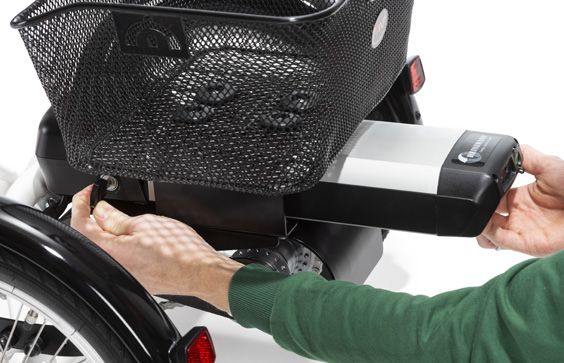
Battery
The battery can be locked and
removed for charging. To charge, plug
the charging cable (A) into the rear of
the opening provided. You can read the B A
progress of loading at any time via the
charge level indicator (B). The charging
time totals approx. 6 hours.
Battery service life
The manufacturer of the E-drive, HEINZMANN, guarantees a minimum of 600
charging cycles for the battery. Appropriate handling / storage and initial
loading (see HEINZMANN user manual) increases its service life.
Range
The mileage of the momo motion. depends on a wide variety of factors:
route (gradients), load / rider weight, level of assistance selected, driving
style. HEINZMANN achieves a range of 40 to 80 km per battery charge.
Please also note the HEINZMANN instructions for use.
2.10 Light system
The lighting system on the momo motion.
is powered by the Li-ion high-power
battery (11Ah).18 3. Settings.
Settings and adjustments to the product or accessories may only be made by
people who have been given the necessary instructions by a medical product
advisor. Please ensure that none of the user's extremities are in the respective
area when making adjustments of any kind to minimise the risk of injury.
3.1 Presettings
The momo motion. is supplied completely
assembled. Prior to initial use, however, the D
following pre-settings must be made.
3.1.1 Handlebar adjustment A
You can find our scope of delivery for
handlebars on page 11 of these Instructions for
use.
Height of handlebars
To adjust the height of the handlebars, D
E
remove the protective cap from the hexagon
socket (A), loosen the hexagon socket (A) and
adjust the stem (B) to the required height. By B
tapping the head of the hexagon socket (E) lightly C
with a hammer, the stem in the fork steerer will
loosen. Then re-tighten the hexagon socket.
Ensure that the marking for the minimum
insertion depth (C) remains on the stem in the
fork steerer and therefore cannot be seen.
F
Handlebar adjustment
To adjust the handlebar position, loosen the clamping screws (D), bring the
handlebars into the required position and then firmly re-tighten the clam-
ping screws (D).
To change the tilt angle on the stem, please loosen the clamping screw (F).
The steerer factory setting is 20°. In this way you can change the distance
between the saddle and the handlebars, and adjust the required handle
height. Then firmly re-tighten the screws again.
After each adjustment, please retighten all screw connections!
After adjustment of the handlebars, there must still be no tension placed
on the brake cables. If necessary, extend the cables!19 3. Settings.
3.1.2 Saddle adjustment
You can find our selection of saddle forms on
page 11 of these Instructions for use.
Saddle height C
The height of the saddle can be adjusted
on the frame saddle tube (A) by pulling the
saddle post in or out. In order to adjust the B
height, please loosen the clamp (B) and bring A
the saddle into the required height. Align the
saddle and tighten the clamp (B) so tightly
that the saddle support no longer twists. The saddle height is to be re-set
based on the inseam length. Here any contractures of the knees must be
taken into consideration. The saddle height should be inspected when
the user is sitting on the saddle. The leg extension should not total 0°. In
the upper position of the pedal, the knee flexion should not be more than
90°. Should it not be possible to achieved this setting through the saddle
height, it is possible to undertake further settings through crank shortening
(see point 4.9 - 4.11).
Adjusting the saddle horizontally
Every saddle (except for the unicycle saddle)
can be minimally adjusted horizontally. To do
this, loosen the nuts (D) with a size 13 wrench D
and push the caliper block (C) forwards or
backwards on the seat stays.
Adjusting the saddle with t-saddle post
horizontally
In order to check the horizontal saddle
position, turn the pedal crank horizontally
forwards and put the foot (while the rider is
sitting on the saddle) onto the pedal. Once
the lower leg is vertical, the saddle position
is correct. You can also loosen the two nuts
(D) under the saddle using a size 13 wrench,
push the saddle to the rear or forwards and
re-tighten the nuts.
During adjustment, the saddle post may not
be pulled out over the respective marking, as in this case sufficient clam-
ping cannot be guaranteed. The markings are in part designed differently.
After each adjustment, please retighten all screw connections!20 3. Settings.
3.2 Brakes
Various brakes are available for the momo motion. depending on the
individual requirements of the user.
3.2.1 Parking brake
The parking brake supports the use
when climbing on and off the tricycle
and secures it against inadvertently
rolling away. To activate the parking
brake, press the lever (A) on the hand-
lebar stem (B) downwards. To release
the parking brake, push the lever up B
again.
Always ensure that the brake or the A
brake blocks function correctly and
have been adjusted (see below).
Adjustment of the parking brake or brake blocks
Ensure that the braking function
immediately takes effect on actuation
of the parking brake lever, taking the
necessary backlash into account. C
Due to "settling" of the Bowden-
cables and the natural wear on the
brake blocks, it is necessary to reset the E
brake after a certain amount of time
or replace the brake blocks. Each gap
between the rim and the brake lining D
should not be larger than 1.5 mm. To
do this, loosen the clamping screw (C),
press the brake blocks together by hand, pull the Bowden cable taut and
then re-tighten the clamping screw. If the brake blocks are not accurately
aligned with the rim edge (D), you must readjust them accordingly. In order
to change the alignment of the brake blocks, loosen the screws (E). Leave
this work to your specialist dealer in case of any uncertainty.
After each adjustment of the cantilever (V) brake, carry out a brake test.
The brake blocks may only be replaced by ones in an identical design.
Observe the manufacture name or marking and the type designation. New
brake blocks do not achieve the required braking effect until they have been
used multiple times.21 3. Settings.
3.2.5 Backpedal brake
The backpedal brake is actuated by pedalling backwards. The drive op-
tions of the freewheel brake hub and the 3 or 7-gear freewheel brake hub
feature a backpedal brake.
The backpedal brake is only functional when the chain sits correctly! If the
chain jumps off, it is not possible to brake using the backpedal brake!
The rear wheel may block in case of strong braking procedures. Risk of
crashes!
During long downhill runs, it is essential that you use the front and rear
brakes in order to avoid overheating of the rear hub brake. This may lead
to brake malfunctions!
3.3 Tyres and hoses
The tyres on the tricycle must always have
sufficient air pressure, otherwise the tyres may
puncture and the rims may be damaged, or
the riding characteristics negatively influeced.
The optimum tyre pressure totals approx. 2.5
- 3.5 bar. If the tyre tread only depresses slightly on being pressed force-
fully with the thumbs, the tyre pressure is correct. For exact values, use a
pressure gauge!
Check all tyres regularly and replace them immediately in case of damage
or wear!
3.4 Chains and chain maintenance
Drive chains must be regularly cared for. This
is in particular the case after riding in rain. The
chain must be lubricated with a commercially B
available chain oil. Due to the expansion
of the chain which is a natural result of use,
regular inspection of the chain tension is
required. Check the chain tension by testing
whether the chain on the tricycle can be pressed A
max. 10 - 15 mm upwards and downwards. In A
order to reset the tension of the chains in the
drive area, loosen the nuts (A) on the hub and pull the hub evenly to the rear.
In the second step, the main chain must be adjusted by shifting the idler
roller (B). Leave this work to your specialist dealer in case of any uncertainty!
After each adjustment, please retighten all screw connections!
An incorrectly-tensioned chain can lead to increased wear!22 4. Accessories.
4.1 Dynamic back and pelvic guide pelotte pads
All back and pelvic guide pelotte pads can
only be used in connection with a holding
bracket (see Point 4.7). For depth adjustment
of the pelotte pad holding bracket, please
loosen the screws (A) on the right and
left-hand sides of the support under the B
saddle, and bring the holding bracket into the
required position. The angular adjustment of the
A
holding bracket takes place after loosening
the screw (B) on the support. The pelotte pads
are adjusted in height after loosening the
screw (C) on the respective support.
C
Only use original accessories, otherwise the
guarantee will be lost.
4.1.1 Width adjustable back and pelvic gui-
de pelotte pads
For information on the height, angle and
depth adjustment of the back and pelvic
guide pelotte pads, see Point 4.1. The width D
adjustable back and pelvic guide pelotte
pads can be adjusted in width. To do this,
loosen the screws (D) on the rear of the back
or pelvic guide pelotte pads and bring them
into the required position.
4.2 Headrest
The headrest can only be used in connection
with a holding bracket (see Point 4.7) and is
adjustable in height. In order to adjust the
height, loosen the screw (E) and bring the
headrest into the required position
After each adjustment, please retighten all E
screw connections!23 4. Accessories.
4.3 Push bar
The push bar is height adjustable and
equipped with an integrated antirotation
lock. In addition, it can be dismantled. In order A
to adjust the height, please loosen the clamp
(A) and bring the push bar into the required
height. In order to remove the entire push bar,
please loosen the clamp (B). Please ensure on B
insertion that the push bar is inserted up to its
limit into the push handle holder, and cannot
be rotated.
Use the push bar only to guide the tricycle!
The push bar is NOT suitable for moving, lifting or tilting the tricycle!
4.4 Brake for accompanying escorts
The brake for the accompanying escort (including motor shutdown and
usable only in conjunction with the push bar) allows an escort to slow down
the tricycle during use. By pressing the brake, the e-drive motor is switched
off. The function of the lever is similar to a normal brake lever.
Always ensure that the brake or the brake blocks function correctly and
have been adjusted (see Point 3.2.1).
4.5 Handlebar lock limiter
The handlebar lock limiter can be adjusted to determine the direction of
travel. In order to adjust the handlebar lock limiter, please loosen all grub
screws (A) and bring the limiter (B) into the
required position. You can determine the
direction by moving both limiters (B) towards
the handlebar stop (C) and tightening them.
D
If possible please leave the settings on the C
handlebar lock limiter as set at the factory! E24 4. Accessories.
4.6 Holding bracket with mount
The holding bracket (A) with mount (B) permits A
head, torso or pelvic supports to be attached, B
which provide the tricycles with additional
stability. Included in the scope of delivery is
the black bracket adapter, which is mounted C
onto the T-saddle post. Then the holding F
bracket is pushed into the holding socket (C) C
and can eb adjusted in depth. To do this,
simply adjust the required position and then
tighten the screws (D). To change the angle of
the back strap, loosen the screw (E), remove
it and insert it into the desired hole (F) on the
mount. Then tighten the screw (E) again.
The use of the holding bracket is exclusively
possible in combination with the T-saddle
post!
E
C
D
4.7 Universal mount
The universal adapter is mounted onto
the holding bracket and is used to mount g
the strap set available for the tricycle.
The universal adapter is adjustable in height.
To do this, simply loosen the screw (G) at the
rear on the adapter and bring the universal
adapter into the required position.25 4. Accessories.
4.8 Crank shortener (continuously adjustable)
The adjustable crank shorteners are to be
mounted onto the cranks with clamps. Please A
note here that the crank shortener marked
"R" is to be mounted on the right-hand side
and the crank shortener marked "L" is to be
mounted on the left-hand side.
The adjustment of the crank shortener is to
be undertaken so that the amplitude of the
pedal depicts the flexibility of the knee joint.
In the lower pedal position, the maximum
extension to be achieved, and in the upper
position, the maximum flexion of the knee is to be achieved. This adjustment
is to be undertaken in interaction with the saddle height. In order to adjust
the continuously adjustable cable shortener, loosen the screw (A) and bring
them into the required position.
4.9 Crank shortener
The crank shortener must be mounted
onto the cranks using the screw included in B
delivery and the clamp, and shortens the crank
by 2.5 or 5 cm. Please note here that the crank
shortener marked "R" is to be mounted on
the right-hand side and the crank shortener
marked "L" is to be mounted on the
left-hand side. The pedal is to be mounted in the
required position in the crank shortener.
The position of the pedals must be conducted so that the amplitude of the
pedal depicts the flexibility of the knee joint. In the lower pedal position, the
maximum extension to be achieved, and in the upper position, the maximum
flexion of the knee is to be achieved. This adjustment is to be undertaken
in interaction with the saddle height. In order to adjust the crank shortener,
loosen the pedals with a 15mm open-end wrench and place it into the
opening (B).
4.10 Special crank for knee contracture
The special crank for knee contractures is
suitable for 20" - 26" tricycles, and can either
be mounted on the left or right-hand side.26 5. Foot positioner.
5.1 Exercise bike pedals A
The exercise bike pedals are characterised by
their integrated balancing weight, whereby
the tread surface automatically balances
itself horizontally. This permits the rider to climb B
on independently. The strap (A) is adjustable
in length, and at the same time provides easy side guidance. To adjust the
length of the strap (A) pull on the lower end in order to loosen the strap (A)
from the plug (B). Now adjust the strap (A) to the required length.
5.2 Foot fixation pedals
The foot fixation pedals are characterised A
through the integrated balancing weight, C B
whereby the treads are automatically
horizontally balanced. This permits the rider
to step onto them independently. The strap
(A) is adjustable in length, and at the same
time provides easy side guidance. The cage
mounted at the front of the pedals (B) prevents the toes from slipping
through at the front. In order to adjust the strap (A) in length, pull the strap
(A) back out of the strap guide (C). Now the strap (A) can be shortened
through pulling and extended through pressing under the lock. To fix the
adjustment, guide the strap (A) back through the strap guide (C).
5.3 Foot pans
The foot pans provides side guidance and F
thus prevents internal or external rotations D D
of the foot. To guarantee this function, the
foot pan is adjustable in width, which can be
conducted by loosening the three screws
(D) and shifting the side part (E) in the
slotted hole. The foot pans are mounted at the E
factory centrally on the pedals. In order to
shift the pressure point under the foot, it must H
be moved in four positions. To do this, the
g
nuts (F) under the pedals must be removed I
and the screws (D) moved into the required
positions. Then the counterplate must be
placed onto the screws (D) and the nuts
(F) must be re-tightened. By loosening the
nuts (F) and twisting the foot pan on the pedal, it is possible to adjust the
rotation. In order to secure the user in the foot pan, pull the snap-in straps
(G) for preliminary fixation. Then fix the straps (H) and (I).27 5. Foot positioner.
5.4 Foot pans with leg guidance
See Point 5.3 for the function and
settings of foot pans. The leg guidance
also stabilises the foot joint and
reduces internal rotation of the leg. A
The adjustment of the leg guidance is A
to be undertaken through loosening of
the screws (A) and moving them in the
slotted hole. The height adjustment
should be selected so that the calf
clamp lies against the vertex of the
calf. By loosening the screw (B) on the
inside of the leg guidance, the calf
clamp can be adjusted in depth.
B
B
5.5 Foot pans with dynamic leg guidance
For the function and adjustment of foot
pans with leg guide, see Point 5.4. The
dynamic leg guidance also permits
defined rotation of the leg and thus
prevents excessive abduction, in
particular of short legs. At the same
time, the stabilisation of the foot
joint is retained. To adjust the degree
of movement of the leg guidance,
loosen the cover (C) and the nut below
it, and screw the elastomer in or out
accordingly. Check the movement
range of the leg guidance.
C28 6. Strap systems.
6.1 Chest strap
The chest strap is attached to the
width adjustable back pelotte pad,
and, if required, ensures secure fixation
of the user. The strap is mounted with
the aid of the plug lock to the back
pelotte pad and threaded through
the strap guidance on the click buckle.
Then the click buckle is pressed down
to fix.
6.2 Positioning vest
The positioning vest is mounted in the
lower area of the width adjustab-
le back pelotte pad. Screw the strap
ends of the positioning vest onto the
universal adapter and tighten the
screws (A). The strap of the positioning
vest is mounted onto the back pelotte
pad with the aid of the plug lock, and
threaded through the strap guidan-
ce on the click buckle. Then the click
buckle is pressed down to fix.
A A29 6. Strap systems.
6.3 Groin harness, T-shaped
The T-shaped groin harness is mounted
onto the width adjustable pelvic
pelotte pad. The strap is mounted onto
the pelvic pelotte pad with the aid of
the plug lock and threaded through
the strap guidance on the click buckle.
Then the click buckle is pressed down
to fix.
6.4 4-point pelvic harness
The 4-point pelvic harness is mounted
onto the width adjustable pelvic pelotte
pad. The strap is mounted onto the
pelvic pelotte pad with the aid of the
plug lock and threaded through the
strap guidance on the click buckle.
Then the click buckle is pressed down
to fix.
6.5 Manual fixation
The manual fixation provides additional
security for the user by keeping their
hands safely on the handlebars. To do
this, the user simply inserts their hand
into the hand fixation and closes the
hook and eye fasteners.30 7. Repairs and cleaning.
7.1 Care and maintenance
In order to retain the functional safety and the appearance of the tricyc-
le, it must be regularly maintained. Please observe the following guidelines:
• N ever allow dirt to dry onto the bicycle, but always remove it with water
and a soft cloth or sponge. Otherwise you may damage the bearings,
the paintwork or the decorations.
• Do not use aggressive cleaning agents. Use a mild detergent solution
to clean.
• Use a standard commercial spray disinfectant to disinfect the saddle,
handlebars and other upholstered parts which come into contact with
the skin.
• Repair paintwork damage immediately.
• In particular in winter, store the bicycle in a dry room with a consistent
temperature.
• Prior to extended storage of the tyres, check the air pressure and, if
necessary, pump them up to the air pressure recommended by the
manufacturer (see Point 8).
• Please also pay attention to our general cleaning and hygiene advice.
This can be found at www.schuchmann.de/en/media-library.31 7. Repairs and cleaning.
7.2 Repairs
Please carry out a daily visual inspection and check the tricycle regularly
for cracks, breaks, missing parts and malfunctions. In case of a defect or
malfunction, please contact the specialist dealer who supplied you with the
product (see Point 11.5).
Storage in winter
Before storing the tricycle in winter, clean it (see Point 8.1) and ensure that it
has sufficient air pressure in the tyres.
Inspection in spring
Before you use the tricycle again in spring, ensure that the air pressure in the
tyres is sufficient and that the tricycle is not damaged.
Work that must be carried out by a specialist workshop at least once a year,
if required:
• Check the chain and chain tension, adjust if necessary, clean and oil.
• Check rear wheel track, adjust if necessary.
• Check bottom bracket and lubricate if necessary.
• Lubricate pedal bearing, check bearing clearance and if necessary
adjust (or replace).
• Check the hub gear and adjust if necessary.
• Check the brake system for function, adjust if necessary. If the brake is
poor, check the hand lever, cable, brake lever and brake pads for their
condition, adjust and replace if necessary.
• Lubricate joints and bearing points.
• Replace bent or trapped cables.
• Check rims for side and top impacts.
• Check the spoke tension and adjust if necessary.
• Check the tyre profile.
• Check the lighting and signal system.
• Check rear hub and lubricate if necessary.
• Check frame and fork for damage and replace if necessary.
• Arrange for annual leakage current measurement to be carried out on
the electric drive.32 7. Repairs and cleaning.
Controls to be performed by the user of the bicycle if necessary:
• Check the chain and chain tension, adjust if necessary, clean and oil.
• Check the chain for wear, oil and replace if necessary.
• Check bottom bracket mounting and repair if necessary.
• Check pedals for clearance.
• Gear system - check settings.
• Check the handlebar and handlebar stem for damage and replace
if necessary.
• Check the brake system for function and adjust if necessary.
• Check the tyre pressure and profile.
• Check the lighting and signal system.
7.3 Spare parts
Only use original accessories, otherwise the guarantee will be lost.
Should you wish to order spare parts, please contact the specialist dealer
who supplied you with the tricycle, stating the serial number (see Point 10.5).
Necessary spare parts and accessories must only be installed by trained
personnel.
7.4 Duration of use and re-use
The expected duration of use of our product, dependent on the usage
intensity and amount of re-use, totals up to "8" years, if the usage takes
place in accordance with the information in these instructions for use. It
may be possible to use the product over and above this time period if it
is in a safe condition. The expected duration of use does not refer to wear
parts, such as for example covers, wheels, batteries.....The maintenance and
evaluation of the condition, and if applicable the potential for re-use, must
be decided by the specialist dealer.
The tricycle is suitable for re-use. Prior to forwarding on, please follow the
cleaning and disinfection instructions stated in Point 7.1. Accompanying
documents such as these Instructions for use are part of the product and
must be passed on to the new user.
7.5 Torque information
Pedal cranks: 40 Nm
Front wheels: 20 Nm - 22 Nm
Heinzmann wheel hub motor: 35 Nm
Rear wheels not driven: 25 Nm to 30 Nm33 8. Technical data.
Dimensions - basic model
16“ 20“ 24“ 26“ 26" (XL)
Pedal to top edge of 42 - 57.5 50 - 64.5 56.5 - 73.5 66.5 - 83 74 - 90.5
A* saddle cm cm cm cm cm
Pedal to top edge of 45 - 60 52 - 68 58 - 81.5 67.5 - 91 75 - 98.5
A** saddle cm cm cm cm cm
Saddle support tube
B to front tube
39 cm 45 cm 52 cm 58 cm 58 cm
C Wheelbase 80 cm 91 cm 104 cm 112 cm 112 cm
D Access point height 18 cm 20 cm 22 cm 23 cm 23 cm
E Full length 120 cm 140 cm 165 cm 178 cm 178 cm
Full width 65 cm 69 cm 75 cm 75 cm 75 cm
Weight 24.5 kg 27 kg 29.5 kg 31.5 kg 31.7 kg
max. load 60 kg 80 kg 100 kg 120 kg 120 kg
2.5 - 3.5 2.5 - 3.5 2.5 - 3.5 2.5 - 3.5 2.5 - 3.5
Max. air pressure
bar bar bar bar bar
* Dimensions with standard saddle post / ** Dimensions with T-saddle post
9. Guarantee.
The two-year statutory guarantee period shall apply for all products. This
begins with the delivery or handover of the goods. Should a verifiable
material or manufacturing fault occur within this time period, we shall, after
carriage paid return to us, view the indicated damage and, if applicable,
either repair or deliver a new product at our discretion.34 10. Identification.
10.1 EC declaration of conformity
Schuchmann GmbH & Co.KG
Dütestr. 3
D-49205 Hasbergen
Tel.: +49 (0) 54 05 / 909 - 0
Fax: +49 (0) 54 05 / 909 - 109
declares on their sole responsibility that the product named below,
classified in product class 1,
momo motion. - the tried-and-tested tricycle with E-drive
Art. no.: 36 02 000 (16“) 36 03 000 (20“) 36 04 000 (24“)
36 05 000 (26“) 36 06 000 (26“ XL)
corresponds with the relevant regulations of the regulations and guidelines:
• EC Directive 93/42/EEC on medical products from 14th June 1993
• DIN EN 12182 Technical aids for the disabled
• EN ISO 14971 Medical products - Application of risk management on
medical products
• DIN EN 14764 City and trekking bicycles - Safety requirements and test
procedure
• DIN EN 14765 Children's bicycles - Safety requirements and test
procedure
• DIN EN 60601-1 Medical electrical devices Part 1: General determinations
for safety including the main performance characteristics
This declaration of conformity applies only for products with the article
numbers and is valid until 31.12.2021.
Date 10.05.2019
Signature
Name Torsten Schuchmann
Function Safety Representative for Medical Products35 10. Identification.
10.2 Serial number / date of manufacture
The serial number, the date of manufacture and other information can be
found on the type plate, which is located on all of our products (A).
Product name
Item number
Serial number
Size
max. load
Date of manufacture A
10.3 Product version
The momo motion. is available in five sizes (16" - 26" XL) and can be
supplemented through a diverse range of accessories (see Point 4).
10.4 Issue of the document
momo motion. instructions for use. - Change status B; Issue 06.2019
10.5 Name and address of the manufacturer, specialist dealer supplying
the product
This product was manufactured by:
Schuchmann GmbH & Co. KG
Dütestraße 3 · 49205 Hasbergen
Tel. +49 (0)5405/909-0 · Fax +49 (0)5405/909-109
info@schuchmann.de · www.schuchmann.de
This product has been delivered by the following specialist dealer:36 10. Identification.
schuchmann.deYou can also read