Mountain Valley Pipeline Project Individual Permit Application - Attachment C: Virginia Marine Resources Commission Permit Modification Request ...
←
→
Page content transcription
If your browser does not render page correctly, please read the page content below
Mountain Valley Pipeline Project

Individual Permit Application
Attachment C: Virginia Marine Resources Commission Permit
Modification Request and Materials

February 2021
Mountain Valley Pipeline Project                                                   USACE, DEP, and DEQ Individual Permit Application and
                                                                                                                       VMRC Permit Modification
                                                                                                                                     February 2021

                                                TABLE OF CONTENTS
Section                                                                                                                                      Page

Contents
          PROJECT & APPLICATION INFORMATION .................................................................................. 1
          PERMIT MODIFICATION REQUEST .............................................................................................. 1
          DESCRIPTION OF TRENCHLESS CROSSING METHODS PROPOSED FOR VMRC
          JURISDICTIONAL STREAMS ......................................................................................................... 3
          3.1   Conventional Bore............................................................................................................... 3
          3.2   Guided Conventional Bore .................................................................................................. 4
          3.3   Microtunneling ..................................................................................................................... 4
          STATUS OF VMRC STREAMS NOT INCLUDED IN THIS REQUEST .......................................... 5
          ADDITIONAL INFORMATION ......................................................................................................... 6

Tetra Tech                                                                                                                                    Page i
Mountain Valley Pipeline Project                          USACE, DEP, and DEQ Individual Permit Application and
                                                                                      VMRC Permit Modification
                                                                                                 February 2021

                                              TABLES
Tables
Table 1:                           Proposed VMRC Stream Crossing Method Modifications
Table 2:                           VMRC Streams Not Included in Request

                                        ATTACHMENTS
Attachments
Attachment C-1                     Joint Permit Application
Attachment C-2                     VMRC Stream Overview Map
Attachment C-3                     Stream Impact Plans and Cross Sections
Attachment C-4                     Correspondence with VDCR
Attachment C-5                     Adjacent Property Owner Map and Owner Information List

Tetra Tech                                                                                              Page ii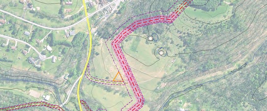
Mountain Valley Pipeline Project                             USACE, DEP, and DEQ Individual Permit Application and
                                                                                         VMRC Permit Modification
                                                                                                    February 2021

          PROJECT & APPLICATION INFORMATION
Mountain Valley Pipeline, LLC (Mountain Valley1) is seeking an Individual Permit from the United States
Army Corps of Engineers (USACE) Pittsburgh, Huntington, and Norfolk Districts to conduct regulated
activities below the ordinary high water elevation of navigable waters under Section 10 of the Rivers and
Harbors Act of 1899 and for the discharge of dredged and fill material into Waters of the United States
under Section 404 of the Clean Water Act for the Mountain Valley Pipeline Project (Project). In addition to
the USACE Individual Permit Application, Mountain Valley is seeking Clean Water Act Section 401 Water
Quality Certification from the West Virginia Department of Environmental Protection (DEP) and the Virginia
Department of Environmental (DEQ) for portions of the Project within their respective jurisdiction.2
Due to the large volume of materials included in this submission and for the convenience of Virginia Marine
Resources Commission (VMRC) staff, Mountain Valley has consolidated materials relevant to the VMRC
permit modification request in this attachment.

          PERMIT MODIFICATION REQUEST
On January 25, 2018, the Virginia Marine Resources Commission (VMRC) issued a permit (#2017-1609)
for impacts to 18 VMRC-regulated streams associated with the Mountain Valley Pipeline Project. The permit
authorized Mountain Valley to install the crossing of the Pigg River (S-E11) using the horizontal directional
drilling (HDD) method and the Stony Creek (S-S5) crossing using the conventional bore method. The
remaining 16 crossings were planned and approved to be constructed using the open cut method. That
permit was extended on January 19, 2021 and remains active through January 31, 2024.
In the course of preparing this multi-agency permit application, Mountain Valley has conducted a detailed
reevaluation of every stream and wetland associated with the Project to identify opportunities to avoid and
minimize aquatic impacts where appropriate and practicable. As a result of that analysis, Mountain Valley
is now seeking approval to use trenchless crossing methods on several stream and wetland resources,
including eight streams subject to VMRC jurisdiction.
Mountain Valley respectfully requests that its existing VMRC permit (#2017-1609) be modified to reflect the
change in proposed crossing method for the streams identified in the Table 1 below.3 Condition 7 of the
permit directs MVP to “minimize the adverse effects of the project upon adjacent properties and wetlands
and upon the natural resources of the Commonwealth” to the “greatest extent practicable.” The use of
trenchless crossing methods is consistent with Condition 7 because Mountain Valley would avoid or
minimize instream impacts to subaqueous bottomlands, thereby eliminating direct impacts to the aquatic

1 Mountain Valley is a joint venture between EQM Midstream Partners, LP; NextEra Capital Holding, Inc;
Con Edison Transmission, Inc.; WGL Midstream; and RGC Midstream, LLC.
2 Additional detailed Project information can be found in Section 1of the Individual Permit Application

narrative.
3 Mountain Valley understands that VMRC may elect to process this modification request as a new permit

application. This application package includes all information necessary to process the request as a new
application.

Tetra Tech                                                                                                 Page 1
Mountain Valley Pipeline Project                               USACE, DEP, and DEQ Individual Permit Application and
                                                                                           VMRC Permit Modification
                                                                                                      February 2021

environment at the location of the crossing and reducing downstream sediment impacts.4 Mountain Valley
is not proposing to use the HDD method for any crossings, which means the potential risk of an inadvertent
return of drilling fluids to streams is negligible to nonexistent. Lastly, the use of trenchless crossing methods
would not change the location or area of any previously authorized encroachment on State-owned
bottomlands.
Mountain Valley is proposing to modify the approved crossing method for the following VMRC-jurisdictional
streams.

                  Table 1. Proposed VMRC Stream Crossing Method Modifications

                                              Previously
                                                                     Proposed                Other Approvals
    Stream                 County             Authorized
                                                                     Crossing Method         Needed5
                                              Crossing Method
    Sinking Creek                             Dry-Ditch
                           Giles                                     Conventional Bore       FERC
    (S-NN17)                                  Open-Cut
    Little Stony Creek                        Dry-Ditch              Guided
                           Giles                                                             FERC
    (S-Z13)                                   Open-Cut               Conventional Bore
    Bradshaw Creek                            Dry-Ditch
                           Montgomery                                Conventional Bore       FERC
    (S-C21)                                   Open-Cut
    Craig Creek                               Dry-Ditch
                           Montgomery                                Conventional Bore       FERC
    (S-OO6)                                   Open-Cut
    Roanoke River                             Dry-Ditch                                      FERC
                           Montgomery                                Microtunnel
    (S-NN16)                                  Open-Cut                                       USACE
    Mill Creek                                Dry-Ditch
                           Roanoke                                   Conventional Bore       FERC
    (S-IJ43)                                  Open-Cut
    Teels Creek                               Dry-Ditch
                           Franklin                                  Conventional Bore       FERC
    (S-C17)                                   Open-Cut
    Harpen Creek                              Dry-Ditch
                           Pittsylvania                              Conventional Bore       FERC
    (S-C3)                                    Open-Cut

4
  Due to site logistics trenchless crossings sometimes necessitate that timber mats or other structures are
placed in aquatic resources (temporary fill) for the duration of the crossing to support the construction
equipment crossing. Trenchless crossings where minor and temporary impacts are anticipated are
indicated on the stream impact table and Stream Impact Plans and Cross Sections included in this
appendix.

5 This column lists other federal or state approvals Mountain Valley must obtain to complete trenchless
crossing methods for these streams. Note that FERC approval has been issued for the trenchless crossings
of the Roanoke River, Craig Creek, and Stony Creek. USACE approval is needed to cross the Roanoke
River because it is subject to Section 10 of the Rivers and Harbors Act. Additionally, any temporary impacts
associated with equipment crossings (see footnote 4 above) are included in the permit applications to
USACE and DEQ.

Tetra Tech                                                                                                   Page 2
Mountain Valley Pipeline Project                             USACE, DEP, and DEQ Individual Permit Application and
                                                                                         VMRC Permit Modification
                                                                                                    February 2021

To date, Mountain Valley has successfully completed 73 trenchless crossings without a failure.
Nevertheless, unanticipated subsurface geotechnical conditions may prevent boring equipment from
completing the crossing. In those cases, it may become necessary to discontinue the boring operation and
complete the crossing with an open cut method. VMRC accounted for that possibility in Mountain Valley’s
permit by including the following statement in Condition 26: “Permittee agrees to install the proposed
pipeline beneath the Pigg River by the horizontal directional drill method, and Stony Creek by the
conventional bore method, to minimize impacts to state and federally listed species. . . . If these crossings
methodologies cannot be completed successfully due to unfavorable onsite conditions, both may be
undertaken utilizing the open-cut dam and pump crossing methodology.” Mountain Valley requests that the
same or similar condition be applicable to the above-proposed crossing method modifications.

          DESCRIPTION OF TRENCHLESS CROSSING METHODS
          PROPOSED FOR VMRC JURISDICTIONAL STREAMS
The trenchless crossing methods Mountain Valley proposes to use for the VMRC streams included in the
request are discussed in Section 5.1.1 of the application narrative. For convenience, summaries from that
section are copied here.

3.1       Conventional Bore
Conventional bore is a technique commonly used in pipeline construction to avoid impacting a sensitive
resource, road crossing, or railroad crossing. Mountain Valley has successfully completed conventional
bore crossings under 67 resources on the Project to date. When using a conventional bore, the pipe is
installed beneath the waterbody or wetland, thereby avoiding open trenching across waterbodies and
wetlands and avoiding the aquatic impacts associated with working directly within waterbodies and
wetlands. Conventional bores allow for uninterrupted existing streamflow and undisturbed wetland
vegetation, thereby minimizing impacts to aquatic resources, preserving wetland and wildlife habitat, and
minimizing areas of permanent wetland conversion.
The conventional bore method, or auger bore, requires excavation of launching and receiving pits located
in workspace in uplands on each side of the feature being crossed. The bore-pit excavations are sloped or
shored to comply with all local, state, and federal safety regulations. Prior to construction, wetlands and
waterbodies adjacent to each work site are protected using the erosion and sediment control devices and
best management practices appropriate to the specific site. Bore pits produce spoil piles from the excavated
material to create the pit, which are monitored and managed until the bore is complete and the bore pits
are backfilled. The volume of spoil generated during boring operations is generally comparable to that
generated during open-cut crossings—although the pits may be deeper, a trench is longer. The cuttings
from the bore may also be stockpiled on site and are used to backfill the bore pits. Any spoil remaining is
spread evenly over the right-of-way or hauled away.
Bore-pit dewatering may be required and, if so, is accomplished in accordance with the Project’s applicable
DEQ-approved erosion and sediment control plans and FERC requirements. Bore-pit dewatering may be
required 24 hours per day. The specific need for, and amount of, dewatering required for any given
waterbody or wetland crossing can vary over short periods of time due to recent precipitation and other
factors. It cannot be determined until each individual trench or bore-pit excavation begins.
Conventional boring’s major advantage over some other boring technologies is that the drill pipe is installed
as the boring is advanced and the line pipe is installed immediately behind the bore pipe once the boring is
completed, leaving no unsupported hole that could potentially collapse. Because the borehole is
continuously supported by pipe throughout the process, the risk of bore collapse is minimal.
Conventional boring typically requires the least amount of areal footprint (workspace) of the mechanical
trenchless technologies because drilling fluid tanks and mud-mixing systems are not required. Cuttings
(spoil) generated by boring operations may be stockpiled temporarily at the site but would ultimately be

Tetra Tech                                                                                                 Page 3
Mountain Valley Pipeline Project                               USACE, DEP, and DEQ Individual Permit Application and
                                                                                           VMRC Permit Modification
                                                                                                      February 2021

reused as backfill in the pipeline right-of-way or transported offsite to an appropriate disposal site. Unlike
the Direct Pipe, microtunneling, and guided conventional bore methods that use drilling fluids under
pressure as a slurry to convey cuttings to the surface, a conventional bore conveys cuttings to the surface
mechanically using a screw auger. Because a conventional bore does not convey cuttings using a high-
pressure drilling fluid slurry, this method avoids the potential for an inadvertent return during the crossing.
However, in some situations, particularly in longer bores or in bores through mixed ground or clay, small
quantities of water, bentonite, or polymer-based lubricant may be applied to the cutting head and exterior
of the casing to reduce friction and increase the likelihood of success of the crossing. Any lubricants used
will be non- petrochemical based, non-hazardous, and NSF-60-compliant.

3.2       Guided Conventional Bore
For longer bores, it may be advantageous to utilize an additional preparatory step to ensure the boring
auger stays on path. This minor variation is referred to as “guided conventional bore.” In these situations,
a small diameter “guided pilot” is installed first. The drill string is then attached to the front of the
conventional auger during the final hole opening phase. The pilot hole can be installed by a small diameter
self-propelled, hydraulic steerable drill unit using a tri-cone cutting head. The tri-cone head is anywhere
from 6 to 12 inches and is steered using a bottom-hole assembly. Water typically can be used to carry back
cuttings and cool the head; however, in longer bores a bentonite slurry may be utilized. In extremely hard
rock, an air hammer can be used to establish the pilot. An air hammer uses air to remove cuttings and does
not require a bentonite slurry. When drilling mud or water is needed as the medium to carry back drill
cuttings, the down-hole pressure is monitored at the rig during the pilot boring process to mitigate the risk
of an inadvertent return; the surface is also monitored for inadvertent returns. After the pilot hole is
successfully made across the span, the drill string remains in place and the conventional auger bore
machine completes the bore to the required diameter attaching to the drill stem to keep the conventional
auger bore in line. Because the drill string stays in place, the risk of borehole collapse is minimal. The stems
are removed on the exit side as the auger advances from the launch side. No fluids are utilized during the
conventional auger bore phase.
Except for the additional preparatory step, the guided conventional bore method is materially similar to the
conventional bore method.

3.3       Microtunneling
Microtunneling is an enhanced drilling technique that allows for trenchless construction below features
including roads, railways, rivers, waterbodies, environmentally sensitive areas, landfalls, and shore
approaches. As in a conventional bore, microtunneling typically requires two pits to be excavated, one on
each side of the feature to be bored. These pits are typically closer to the feature being crossed than they
would be for an HDD because HDDs are limited by pipe bend radius and workspace logistics in areas with
steep terrain. Unlike a conventional bore, which typically uses a non-steerable auger to establish the bore
hole, microtunneling utilizes a microtunneling boring machine (MTBM), which uses remote-operated
hydraulic cylinders to steer the machine along the proposed bore path. The primary advantage of
microtunneling over conventional boring is that the steerability of the MTBM enables drilling over longer
distances and mitigates the risk of the bore deviating from the planned profile. The MTBM is typically the
full diameter of the finished bore hole, and the product pipe is inserted behind the MTBM as it completes
the bore and thereby protects and supports the integrity of the borehole from collapse. In comparison to
HDD, microtunneling only requires one drilling pass compared to multiple drilling passes with a product
pipe pullback on an HDD.
The MTBM drilling head uses a drilling mud slurry for lubrication and conveyance of cuttings. While
employing this method, the annular pressure (i.e., the pressure between the product pipe and the bore hole
wall) is drastically reduced in comparison to the HDD method. This is because the MTBM uses fluid only at
the cutting head and the annular space outside the product pipe, while cuttings are conveyed through an
isolated slurry pipe that is fully contained within the product pipe. Therefore, the annular pressure in a
microtunneling operation consists of only the hydrostatic pressure of drilling fluids. By comparison, HDDs

Tetra Tech                                                                                                   Page 4
Mountain Valley Pipeline Project                                 USACE, DEP, and DEQ Individual Permit Application and
                                                                                             VMRC Permit Modification
                                                                                                        February 2021

fill the entire bore hole with drilling fluid and circulate a much larger volume of drilling fluid at higher pressure
to both lubricate the hole and remove cuttings. Microtunneling’s use of a much smaller volume of drilling
fluid at a drastically reduced pressure greatly minimizes the risk of an inadvertent return. An HDD, in
comparison, may have downhole pressures up to ten times the downhole pressure in a microtunnel bore.
By controlling the thrusting force, rate‐of‐penetration, and tunneling pressures the risk for inadvertent return
is drastically reduced in a microtunneling operation compared to the traditional HDD methodology.
Although unmanned, the microtunneling method, due to its advanced control and guidance system, is
capable of installing pipelines to accurate line and grade tolerances and therefore may be preferable in
situations where trenchless installation is needed over longer distances ranging from 200 to 1,500 feet in
length. A wide range of soil types are suitable for installation by microtunneling, including boulders and
rock. Boulders and cobbles up to one-third the diameter of the installed pipe can be accommodated by the
MTBM.
Like conventional bore, utilizing the microtunneling method requires measures to dewater the bore pits.
This method also avoids direct impacts to streams and wetlands.

          STATUS OF VMRC STREAMS NOT INCLUDED IN THIS REQUEST
The following table provides the current status of the other ten VMRC-jurisdictional streams crossed by the
Project.

                              Table 2. VMRC Streams Not Included in Request

 Stream                      County            Status
                                               Pipeline installed on July 21, 2018. Note, a temporary bridge
 North Fork
                                               structure authorized by the current VMRC permit still exists at
 Roanoke River               Montgomery
                                               this crossing to facilitate travel on the right-of-way and will be
 (S-G36)
                                               removed when construction is complete.
 Pigg River (S-E11)          Pittsylvania      Crossing successfully completed June 9, 2019.
 North Fork
                                               To be completed using open-cut method in accordance with
 Blackwater River            Franklin
                                               VMRC permit #2017-1609.
 (S-D8)
 Teels Creek                                   To be completed using open-cut method in accordance with
                             Franklin
 (S-D23)                                       VMRC permit #2017-1609.
 Teels Creek                                   To be completed using open-cut method in accordance with
                             Franklin
 (S-C14)                                       VMRC permit #2017-1609.
 Little Creek                                  To be completed using open-cut method in accordance with
                             Franklin
 (S-CD6)                                       VMRC permit #2017-1609.
 Little Creek                                  To be completed using open-cut method in accordance with
                             Franklin
 (S-II2)                                       VMRC permit #2017-1609.
 Maggodee Creek                                To be completed using open-cut method in accordance with
                             Franklin
 (S-C19)                                       VMRC permit #2017-1609.
 Blackwater River                              To be completed using open-cut method in accordance with
                             Franklin
 (S-F11)                                       VMRC permit #2017-1609.
                                               To be completed using conventional bore in accordance with
 Stony Creek (S-S5)          Giles
                                               VMRC permit #2017-1609.

Tetra Tech                                                                                                     Page 5
Mountain Valley Pipeline Project USACE, DEP, and DEQ Individual Permit Application and
VMRC Permit Modification
February 2021
ADDITIONAL INFORMATION
The following additional information is provided to facilitate VMRC’s review of this request.
The standard Joint Permit Application included in the package is reproduced for convenience in
Attachment C-1 hereto.
A table of proposed VMRC stream crossing method modifications included in this request can be
found in Table 1 (Section 2.0).
A table of VMRC streams not included in this request can be found in Table 2 (Section 4.0).
A location map of VMRC stream impacts included in this request can be found in Attachment C-2.
Stream Impact Plans and Cross Sections can be found in Attachment C-3. Note that these plans
and cross sections are excerpted from the larger applicatoin package.
Several of the streams included in this request are in karst terrain and Mountain Valley has reached
out to the Virginia Department of Conservation and Recreation (DCR) to request their feedback on
the crossing methods proposed in those areas. That correspondence can be found in Attachment
C-4. Mountain Valley will continue to coordinate with DCR as necessary.
Adjacent Property Owner Mapping and Owner Information List can be found in Attachment C-5.
List of newspapers previously used for publication that cover the eight proposed modified
crossings:
o Chatham Star Tribune
o The Franklin News-Post
o The Roanoke Times
Tetra Tech Page 6
Mountain Valley Pipeline Project                   USACE, DEP, and DEQ Individual Permit Application and
                                                                               VMRC Permit Modification
                                                                                          February 2021

                                      ATTACHMENT C-1
                                   Joint Permit Application

Tetra Tech
FOR AGENCY USE ONLY
Notes:
JPA#
APPLICANTS
PLEASE PRINT OR TYPE ALL ANSWERS. If a question does not apply to your project, please print N/A (not applicable) in the space
provided. If additional space is needed, attach extra 8 ½ x 11 inch sheets of paper.
Check all that apply
Pre-Construction Notification (PCN) SPGP DEQ Reapplication Receiving federal funds
NWP # _________ Existing permit number: Agency providing funding:
RP # 05 ___________________ _______________________
(For NWPs & RP 05 ONLY - No DEQ-VWP
permit writer will be assigned)
Regional Permit 17 Checklist (RP-17)
PREVIOUS ACTIONS RELATED TO THE PROPOSED WORK (Include all federal, state, and local pre-application
coordination, site visits, previous permits, or applications whether issued, withdrawn, or denied)
Historical information for past permit submittals can be found online with VMRC - https://webapps.mrc.virginia.gov/public/habitat/ - or VIMS -
http://ccrm.vims.edu/perms/newpermits.html
Agency Action / Activity Permit/Project number, Date of Action If denied, give reason for denial
including any non-reporting
Nationwide permits
previously used (e.g., NWP
13)
See Section 1.2 and Table 9 in the
attached application
1. APPLICANT, AGENT, PROPERTY OWNER, AND CONTRACTOR INFORMATION
The applicant(s) is/are the legal entity to which the permit may be issued (see How to Apply at beginning of form). The
applicant(s) can either be the property owner(s) or the person/people/company(ies) that intend(s) to undertake the activity.
The agent is the person or company that is representing the applicant(s). If a company, please also provide the company
name that is registered with the State Corporation Commission (SCC), or indicate no registration with the SCC.
Legal Name(s) of Applicant(s) Agent (if applicable)
Mountain Valley Pipeline, LLC Tetra Tech, Inc.
Mailing address Mailing address
2200 Energy Drive 661 Anderson Drive ,Foster Plaza 7, Suite 200
City State ZIP Code City State ZIP Code
Canonsburg PA 15317 Pittsburgh PA 15220
Phone number w/area code Fax Phone number w/area code Fax
(724) 271-7600 (412) 921-7090
Mobile E-mail Mobile E-mail
RCooper@equitransmidstream
.com
State Corporation Commission Name and ID number (if State Corporation Commission Name and ID number (if
applicable) applicable)
Mountain Valley Pipeline, LLC T0586216 Tetra Tech, Inc. F0572851
Certain permits or permit authorizations may be provided via electronic mail. If the applicant wishes to receive their
RCooper@equitransmidstream.com
permit via electronic mail, please provide an e-mail address here: ________________________________________________
Application Revised: October 2019 71. APPLICANT, AGENT, PROPERTY OWNER, AND CONTRACTOR INFORMATION (Continued)
Property owner(s) legal name, if different from applicant Contractor, if known
See Table 8 NA
Mailing address Mailing address
City State ZIP code City State ZIP code
Phone number w/area code Fax Phone number w/area code Fax
Mobile E-mail Mobile E-mail
State Corporation Commission Name and ID number (if State Corporation Commission Name ID number (if applicable)
applicable)
2. PROJECT LOCATION INFORMATION
(Attach a copy of a detailed map, such as a USGS topographic map or street map showing the site location and project
boundary, so that it may be located for inspection. Include an arrow indicating the north direction. Include the drainage
area if the SPGP box is checked on Page 7.)
Street Address (911 address if available) City/County/ZIP Code
See Section 1.4, Table 6, and Table 8 See Section 1.4, Table 6, and Table 8
Subdivision Lot/Block/Parcel #
Name of water body(ies) within project boundaries and drainage area (acres or square miles).
See Table 1, Table 2, Table 3, and Table 7
Tributary(ies) to: __________________________________________________
Basin: _______________
See Table 7 Sub-basin: _________________________
See Table 7
(Example: Basin: James River Sub-basin: Middle James River)
See Section 4.2 in attached application
Special Standards (based on DEQ Water Quality Standards 9VAC25-260 et seq.): ______________________________________
Project type (check one) _____ Single user (private, non-commercial, residential)
_____
X Multi-user (community, commercial, industrial, government)
_____ Surface water withdrawal
See Section 1.4
Latitude and longitude at center of project site (decimal degrees): ________________________ / -________________________
(Example: 37.33164/-77.68200)
See Figure 3
USGS topographic map name: ____________________________________________
8-digit USGS Hydrologic Unit Code (HUC) for your project site (See http://cfpub.epa.gov/surf/locate/index.cfm ): See Table 7
______________
If known, indicate the 10-digit and 12-digit USGS HUCs (see http://consapps.dcr.virginia.gov/htdocs/maps/HUExplorer.htm) :
_____________________________________________ _________________________________________
Mountain Valley Pipeline Project
Name of your project (Example: Water Creek driveway crossing) ___________________________________________________
✔ Yes __ No. If yes, check all that apply: __
Is there an access road to the project? __ ✔ public __
✔ private __
✔ improved __
✔ unimproved
2,143 acres in Virginia
Total size of the project area (in acres): _________________________________________________________________
Application Revised: October 2019 82. PROJECT LOCATION INFORMATION (Continued)
Provide driving directions to your site, giving distances from the best and nearest visible landmarks or major intersections:
See Section 1.4 and Section 1.8 in the attached application
Does your project site cross boundaries of two or more localities (i.e., cities/counties/towns)? __
✔ Yes __ No
If so, name those localities: See Table 6
3. DESCRIPTION OF THE PROJECT, PROJECT PRIMARY AND SECONDARY PURPOSES, PROJECT NEED, INTENDED
USE(S), AND ALTERNATIVES CONSIDERED (Attach additional sheets if necessary)
The purpose and need must include any new development or expansion of an existing land use and/or proposed future use of
residual land.
Describe the physical alteration of surface waters, including the use of pilings (#, materials), vibratory hammers, explosives,
and hydraulic dredging, when applicable, and whether or not tree clearing will occur (include the area in square feet and time of
year).
Include a description of alternatives considered and measures taken to avoid or minimize impacts to surface waters, including
wetlands, to the maximum extent practicable. Include factors such as, but not limited to, alternative construction technologies,
alternative project layout and design, alternative locations, local land use regulations, and existing infrastructure
For utility crossings, include both alternative routes and alternative construction methodologies considered
For surface water withdrawals, public surface water supply withdrawals, or projects that will alter in-stream flows, include the
water supply issues that form the basis of the proposed project.
See Section 1.2 and Section 1.4 for Project description and location.
See Section 2 for Project purpose, need, and uses.
See Section 3 for the Project's alternative analysis.
See Section 5 and Table 15 for information on wetland and waterbody crossing methods and a description of impact
avoidance, minimization, and compensation.
Date of proposed commencement of work (MM/DD/YYYY) Date of proposed completion of work (MM/DD/YYYY)
____________________
Upon approval ____________________
12/31/2021
Are you submitting this application at the direction of any state, Has any work commenced or has any portion of the project for
local, or federal agency? _____Yes _____No
X which you are seeking a permit been completed?
_____
X Yes _____ No
If you answered “yes” to either question above, give details stating when the work was completed and/or when it commenced, who
performed the work, and which agency (if any) directed you to submit this application. In addition, you will need to clearly
differentiate between completed work and proposed work on your project drawings.
See Section 1.2, Table 10, Table 11, and Figure 2
X
Are you aware of any unresolved violations of environmental law or litigation involving the property? _____Yes ____No
(If yes, please explain)
No unresolved violations of environmental law.
See Section 1.2 for litigation involving the property.
Application Revised: October 2019 94. PROJECT COSTS
>1,100,000,000
Approximate cost of the entire project, including materials and labor: $_________________
Approximate cost of only the portion of the project affecting state waters (channelward of mean low water in tidal areas and below
ordinary high water mark in nontidal areas): $ __________________
>500,000
5. PUBLIC NOTIFICATION (Attach additional sheets if necessary)
Complete information for all property owners adjacent to the project site and across the waterway, if the waterway is less than 500
feet in width. If your project is located within a cove, you will need to provide names and mailing addresses for all property owners
within the cove. If you own the adjacent lot, provide the requested information for the first adjacent parcel beyond your property
line. Per Army Regulation (AR 25-51) outgoing correspondence must be addressed to a person or business.
Failure to provide this information may result in a delay in the processing of your application by VMRC.
Property owner’s name Mailing address City State ZIP code
See Table 8
See Section 6.0
Name of newspaper having general circulation in the area of the project: _____________________________________________
Address and phone number (including area code) of
newspaper______________________________________________________________________________________
See Section 6.0
X
Have adjacent property owners been notified with forms in Appendix A? _____Yes _____No (attach copies of distributed forms)
6. THREATENED AND ENDANGERED SPECIES INFORMATION
Please provide any information concerning the potential for your project to impact state and/or federally threatened and endangered
species (listed or proposed). Attach correspondence from agencies and/or reference materials that address potential impacts, such
as database search results or confirmed waters and wetlands delineation/jurisdictional determination. Include information when
applicable regarding the location of the project in Endangered Species Act-designated or -critical habitats. Contact information for
the U.S. Fish and Wildlife Service, National Oceanic and Atmospheric Administration, Virginia Dept. of Game and Inland Fisheries,
and the Virginia Dept. of Conservation and Recreation-Division of Natural Heritage can be found on page 4 of this package.
7. HISTORIC RESOURCES INFORMATION
Note: Historic properties include but are not limited to archeological sites, battlefields, Civil War earthworks, graveyards, buildings, bridges, canals,
etc. Prospective permittees should be aware that section 110k of the NHPA (16 U.S.C. 470h-2(k)) prevents the USACE from granting a permit or
other assistance to an applicant who, with intent to avoid the requirements of Section 106 of the NHPA, has intentionally significantly adversely
affected a historic property to which the permit would relate, or having legal power to prevent it, allowed such significant adverse effect to occur,
unless the USACE, after consultation with the Advisory Council on Historic Preservation (ACHP), determines that circumstances justify granting
such assistance despite the adverse effect created or permitted by the applicant.
X Yes ____ No _____ Uncertain
Are any historic properties located within or adjacent to the project site? ____
If Yes, please provide a map showing the location of the historic property within or adjacent to the project site.
X Yes
Are there any buildings or structures 50 years old or older located on the project site? ____ ____ No _____ Uncertain
If Yes, please provide a map showing the location of these buildings or structures on the project site.
X
Is your project located within a historic district? ____ Yes ____ No ____ Uncertain
See Section 1.9.3 and Section 4.4.6
If Yes, please indicate which district: _________________________________________________________________________
Application Revised: October 2019 107. HISTORIC RESOURCES INFORMATION (Continued)
Has a survey to locate archeological sites and/or historic structures been carried out on the property?
___
X Yes ___ No ___ Uncertain
See Section 1.9.3 and Section 4.4.6
If Yes, please provide the following information: Date of Survey: ____________________________________
Tetra Tech, Inc., New South Associates
Name of firm: _____________________________________________________________________
X
Is there a report on file with the Virginia Department of Historic Resources? ____ Yes ____ No ___Uncertain
See Section 1.9.3 and Section 4.4.6
Title of Cultural Resources Management (CRM) report: ____________________________________________________
X
Was any historic property located? ____ Yes ____ No __ Uncertain
8. WETLANDS, WATERS, AND DUNES/BEACHES IMPACT INFORMATION
Report each impact site in a separate column. If needed, attach additional sheets using a similar table format. Please
ensure that the associated project drawings clearly depict the location and footprint of each numbered impact site. For
dredging, mining, and excavating projects, use Section 17.
Impact site Impact site Impact site Impact site Impact site
number number number number number
1 2 3 4 5
Impact description (use See Table B-1 and
all that apply): Table B-2 within
F=fill Attachment B
EX=excavation
S=Structure
T=tidal
NT=non-tidal
TE=temporary
PE=permanent
PR=perennial
IN=intermittent
SB=subaqueous bottom
DB=dune/beach
IS=hydrologically isolated
V=vegetated
NV=non-vegetated
MC=Mechanized Clearing
of PFO
(Example: F, NT, PE, V)
Latitude / Longitude (in
decimal degrees)
Wetland/waters impact
area
(square feet / acres)
Dune/beach impact area
(square feet)
Stream dimensions at
impact site
(length and average width
in linear feet, and area in
square feet)
Volume of fill below Mean
High Water or Ordinary
High Water (cubic yards)
Application Revised: October 2019 118. WETLANDS/WATERS IMPACT INFORMATION (Continued)
Cowardin classification of
impacted wetland/water See Table B-1 and
Table B-2 within
or geomorphological
Attachment B
classification of stream
Example wetland: PFO;
Example stream: ‘C’ channel
and if tidal, whether
vegetated or non-vegetated
wetlands per Section 28.2-
1300 of the Code of Virginia
Average stream flow at
site
(flow rate under normal
rainfall conditions in cubic
feet per second) and method
of deriving it (gage, estimate,
etc.)
Contributing drainage
area in acres or square
miles (VMRC cannot
complete review without this
information)
DEQ classification of
impacted resource(s):
Estuarine Class II
Non-tidal waters Class
III
Mountainous zone
waters Class IV
Stockable trout waters
Class V
Natural trout waters
Class VI
Wetlands Class VII
https://law.lis.virginia.gov
For DEQ permitting purposes, also submit as part of this section a wetland and waters boundary delineation map –
see (3) in the Footnotes section in the form instructions.
For DEQ permitting purposes, also submit as part of this section a written disclosure of all wetlands, open water, or
streams that are located within the proposed project or compensation areas that are also under a deed restriction,
conservation easement, restrictive covenant, or other land-use protective instrument.
9. APPLICANT, AGENT, PROPERTY OWNER, AND CONTRACTOR CERTIFICATIONS
READ ALL OF THE FOLLOWING CAREFULLY BEFORE SIGNING
PRIVACY ACT STATEMENT: The Department of the Army permit program is authorized by Section 10 of the Rivers and Harbors
Act of 1899, Section 404 of the Clean Water Act, and Section 103 of the Marine Protection Research and Sanctuaries Act of 1972.
These laws require that individuals obtain permits that authorize structures and work in or affecting navigable waters of the United
States, the discharge of dredged or fill material into waters of the United States, and the transportation of dredged material for the
purpose of dumping it into ocean waters prior to undertaking the activity. Information provided in the Joint Permit Application will be
used in the permit review process and is a matter of public record once the application is filed. Disclosure of the requested
information is voluntary, but it may not be possible to evaluate the permit application or to issue a permit if the information
requested is not provided.
CERTIFICATION: I am hereby applying for permits typically issued by the DEQ, VMRC, USACE, and/or Local Wetlands Boards for
the activities I have described herein. I agree to allow the duly authorized representatives of any regulatory or advisory agency to
enter upon the premises of the project site at reasonable times to inspect and photograph site conditions, both in reviewing a
proposal to issue a permit and after permit issuance to determine compliance with the permit.
In addition, I certify under penalty of law that this document and all attachments were prepared under my direction or supervision in
accordance with a system designed to assure that qualified personnel properly gather and evaluate the information submitted.
Based on my inquiry of the person or persons who manage the system or those persons directly responsible for gathering the
information, the information submitted is, to the best of my knowledge and belief, true, accurate, and complete. I am aware that
there are significant penalties for submitting false information, including the possibility of fine and imprisonment for knowing
violations.
Application Revised: October 2019 129. APPLICANT, AGENT, PROPERTY OWNER, AND CONTRACTOR CERTIFICATIONS (Continued)
✔ No
Is/Are the Applicant(s) and Owner(s) the same? ___ Yes ___
Legal name & title of Applicant Second applicant’s legal name & title, if applicable
Robert J. Cooper - SVP, MVP Engineering and Construction N/A
Applicant’s signature Second applicant’s signature
Date Date
2/19/2021
Property owner’s legal name, if different from Applicant Second property owner’s legal name, if applicable
See Table 8 See Table 8
Property owner’s signature, if different from Applicant Second property owner’s signature
Date Date
CERTIFICATION OF AUTHORIZATION TO ALLOW AGENT(S) TO ACT ON APPLICANT’S(S’) BEHALF (IF APPLICABLE)
Mountain Valley Pipeline, LLC N/A
I (we), ____________________________________ (and) _________________________________ ,
APPLICANT’S LEGAL NAME(S) – complete the second blank if more than one Applicant
Henry Schumacher N/A
hereby certify that I (we) have authorized ______________________________ (and) ________________________________
AGENT’S NAME(S) – complete the second blank if more than one Agent
to act on my (our) behalf and take all actions necessary to the processing, issuance, and acceptance of this permit and any and all
standard and special conditions attached. I (we) hereby certify that the information submitted in this application is true and accurate
to the best of my (our) knowledge.
Applicant’s signature Second applicant’s signature, if applicable
N/A
Date Date
2/19/2021 N/A
Agent’s signature and title Second agent’s signature and title, if applicable
Sr. Ecologist N/A
Date Date
2/19/2021 N/A
CONTRACTOR ACKNOWLEDGEMENT (IF APPLICABLE)
N/A N/A
I (we), ___________________________________________ (and) ___________________________________________ ,
APPLICANT’S LEGAL NAME(S) – complete the second blank if more than one Applicant
N/A N/A
have contracted _______________________________________ (and) _______________________________________
CONTRACTOR’S NAME(S) – complete the second blank if more than one Contractor
N/A
to perform the work described in this Joint Permit Application, signed and dated ___________________________________.
I (we) will read and abide by all conditions as set forth in all federal, state, and local permits as required for this project. I (we)
understand that failure to follow the conditions of the permits may constitute a violation of applicable federal, state, and local
statutes and that we will be liable for any civil and/or criminal penalties imposed by these statutes.
In addition, I (we) agree to make available a copy of any permit to any regulatory representative visiting the project site to ensure
permit compliance. If I (we) fail to provide the applicable permit upon request, I (we) understand that the representative will have
the option of stopping our operation until it has been determined that we have a properly signed and executed permit and are in full
compliance with all of the terms and conditions.
Contractor’s name or name of firm (printed/typed) Contractor’s or firm’s mailing address
N/A N/A
Contractor’s signature and title Contractor’s license number Date
N/A N/A N/A
Applicant’s signature Second applicant’s signature, if applicable
N/A N/A
Date Date
N/A N/A
Application Revised: October 2019 13END OF GENERAL INFORMATION
The following sections are activity-specific. Fill out only the sections that apply to your particular project.
10. PRIVATE PIERS, MARGINAL WHARVES, AND UNCOVERED BOAT LIFTS
Regional Permit 17 (RP-17), authorizes the installation and/or construction of open-pile piers, mooring structures/devices, fender
piles, covered boathouses/boatslips, boatlifts, osprey pilings/platforms, accessory pier structures, and certain devices associated
with shellfish gardening, for private use, subject to strict compliance with all conditions and limitations further set out in the RP-17
enclosure located at http://www.nao.usace.army.mil/Missions/Regulatory/RBregional/. In addition to the information required in this
JPA, prospective permittees seeking authorization under RP-17 must complete and submit the ‘Regional Permit 17 Checklist’ with
their JPA. A copy of the ‘Regional Permit 17 Checklist’ is found in Appendix B of this application package. If the prospective
permittee answers “yes” (or “N/A”, where applicable) to all of the questions on the ‘Regional Permit 17 Checklist’, the permittee is in
compliance with RP-17 and will not receive any other written authorization from the Corps but may not proceed with construction
until they have obtained all necessary state and local permits. Note: If the prospective permittee answers “no” to any of the
questions on the ‘Regional Permit 17 Checklist’ then their proposed structure(s) does not meet the terms and conditions
of RP-17 and written authorization from the Corps is required before commencement of any work.
If the prospective permittee answers “no” to any of the questions on the ‘Regional Permit 17 Checklist’ then their proposed
structure(s) does not meet the terms and conditions of RP-17 and written authorization from the Corps is required before
commencement of any work. In those circumstances, the following information must be included in the application and/or on the
drawings in order for the application to be considered complete:
1. The applicant MUST provide written justification/need for the encroachment if the proposed structure(s) will extend
greater than one- fourth of the distance across the waterway measured from either mean high water to mean high water
(including all channelward wetlands) or ordinary high water to ordinary high water (including all channelward wetlands).
The measurement should be based on the narrowest distance across the waterway regardless of the orientation of the
proposed structure(s).
2. The applicant MUST provide written justification/need if the proposed structure(s) is greater than five (5) feet wide or
there will be less than four (4) feet elevation between the decking and the vegetated wetlands substrate.
3. The Corps MAY require depth soundings across the waterway at increments designated by the Corps project manager.
Inclusion of depth sounding data in the original JPA submittal is highly recommended in order to expedite permit
evaluation. Depth soundings are typically taken at 10-foot increments for waterways less than 200 feet wide and 20-foot
increments for waterways greater than 200 feet wide. Please include the date and time the measurements were taken,
whether the data was collected at mean low water (MLW) or MHW, and how the soundings were taken (e.g., tape, range
finder, etc.).
Number of vessels to be moored Do you have an existing pier on your property? ____Yes____ No
at the pier or wharf:
If yes, will it be removed? ____Yes ____No
______________
N/A
Is your lot platted to the mean low water shoreline? ____Yes ____No
In the spaces provided below, give the type (e.g., sail, power, skiff, etc.), size, and registration number of the vessel(s) to be
moored
TYPE LENGTH WIDTH DRAFT REGISTRATION #
N/A N/A N/A N/A N/A
11. BOATHOUSES, GAZEBOS, COVERED BOAT LIFTS, AND OTHER ROOFED STRUCTURES OVER WATERWAYS
Number of vessels to be moored at the proposed structure: Will the sides of the structure be enclosed? _____Yes _____No
__________ Area covered by the roof structure ________ square feet
In the spaces provided below, give the type (e.g., sail, power, skiff, etc.), size, and registration number of the vessel(s) to be
moored
TYPE LENGTH WIDTH DRAFT REGISTRATION #
N/A N/A N/A N/A N/A
Application Revised: October 2019 1412. MARINAS AND COMMERCIAL, GOVERNMENTAL, AND COMMUNITY PIERS
Have you obtained the Virginia Department of Health’s approval for sanitary facilities? _____Yes _____No
You will need to obtain this authorization or a variance before a VMRC permit will be issued.
Will petroleum products or other hazardous materials be stored or handled at the facility? _____Yes _____No
If your answer is yes, please attach your spill contingency plan.
Will the facility be equipped to off-load sewage from boats? _____Yes _____No
EXISTING: wet slips: ______ dry storage: ______ PROPOSED: wet slips: ______ dry storage: ______
13. FREE STANDING MOORING PILES, OSPREY NESTING POLES, MOORING BUOYS, AND DOLPHINS
(not associated with piers)
Type and number of mooring(s) proposed:
Number of vessels to be moored: ___________
N/A ___________________________________________________
N/A
In the spaces provided below, give the type (e.g., sail, power, skiff, etc.), size, and registration number of the vessel(s) to be
moored
TYPE LENGTH WIDTH DRAFT REGISTRATION #
N/A N/A N/A N/A N/A
Give the name and complete mailing address(es) of the owner(s) of the vessel(s) if not owned by applicant (attach extra sheets if
needed):
N/A
Do you plan to reach the mooring from your own upland property? _____Yes _____No
If “no,” explain how you intend to access the mooring.
N/A
14. BOAT RAMPS
Will excavation be required to construct the boat ramp? _____Yes _____No. If “yes,” will any of the excavation occur below the
plane of the ordinary high water mark/mean high water line or in wetlands? _____Yes _____No. If “yes,” you will need to fill out
Section 17 for this excavation.
Where will you dispose of the excavated material?
N/A
_______________________________________________________________________________________________________
What type of design and materials will be used to construct the ramp (open pile design with salt treated lumber, concrete slab on
gravel bedding, etc.)?
N/A
Location of nearest public boat ramp
N/A Driving distance to that public ramp _______________miles
N/A
Will other structures be constructed concurrent with the boat ramp installation? _____Yes _____No
If “yes,” please fill out the appropriate sections of this application associated with those other activities.
Application Revised: October 2019 1515. TIDAL/NONTIDAL SHORELINE STABILIZATION STRUCTURES (INCLUDING BULKHEADS AND ASSOCIATED
BACKFILL, RIPRAP REVETMENTS AND ASSOCIATED BACKFILL, MARSH TOE STABILIZATION, GROINS, JETTIES, AND
BREAKWATERS, ETC.) Information on non-structural, vegetative alternatives (i.e., Living Shoreline) for shoreline stabilization is
available at http://ccrm.vims.edu/coastal_zone/living_shorelines/index.html.
Is any portion of the project maintenance or replacement of an existing and currently serviceable structure? _____Yes _____No
If yes, give length of existing structure: __________
N/A linear feet
If your maintenance project entails replacement of a bulkhead, is it possible to construct the replacement bulkhead within 2 feet
channelward of the existing bulkhead? _____Yes
N/A _____No If not, please explain below:
N/A
Length of proposed structure, including returns: _______________linear
N/A feet
Average channelward encroachment of the structure from Maximum channelward encroachment of the structure from
Mean high water/ordinary high water mark: ____________
N/A feet Mean high water/ordinary high water mark: ____________
N/A feet
Mean low water: _____________feet
N/A Mean low water: _____________feet
N/A
Maximum channelward encroachment form the back edge of the
Maximum channelward encroachment from the back edge of the
Dune ________feet
N/A
Beach _________feet
N/A
Describe the type of construction including all materials to be used (including all fittings). Will filter cloth be used? ____Yes
____No
N/A
What is the source of the backfill material? ________________
N/A
What is the composition of the backfill material? _______________________________________________________________
N/A
If rock is to be used, give the average volume of material to be used for every linear foot of construction: ___________cubic
N/A yards
What is the volume of material to be placed below the plane of ordinary high water mark/mean high water? ___________cubic
N/A
yards
For projects involving stone:
Average weight of core material (bottom layers): ___________pounds
N/A per stone (Class________)
Average weight of armor material (top layers): _____________pounds
N/A per stone (Class________)
Are there similar shoreline stabilization structures in the vicinity of your project site? _____Yes _____No
If so, describe the type(s) and location(s) of the structure(s):
N/A
If you are building a groin or jetty, will the channelward end of Has your project been reviewed by the Shoreline Erosion
the structure be marked to show a hazard to navigation? Advisory Service (SEAS)? _____Yes _____No
_____Yes _____No If yes, please attach a copy of their comments.
16. BEACH NOURISHMENT
Source of material and composition (percentage sand, silt, clay):
Volume of material: _______________________cubic
N/A yards
___________________________________________________
N/A
Area to be covered _________
N/A square feet channelward of mean low water ________square
N/A feet channelward of mean high water
_________
N/A square feet landward of mean low water __________square
N/A feet channelward of mean high water
Mode of transportation of material to the project site (truck, pipeline, etc.):
N/A
Application Revised: October 2019 1616. BEACH NOURISHMENT (Continued)
Describe the type(s) of vegetation proposed for stabilization and the proposed planting plan, including schedule, spacing,
monitoring, etc. Attach additional sheets if necessary.
N/A
17. DREDGING, MINING, AND EXCAVATING
FILL OUT THE FOLLOWING TABLE FOR DREDGING PROJECTS
NEW dredging MAINTENANCE dredging
Hydraulic Mechanical (clamshell, Hydraulic Mechanical (clamshell,
dragline, etc.) dragline, etc.)
Cubic yards Square feet Cubic yards Square feet Cubic yards Square feet Cubic yards Square feet
Vegetated wetlands
N/A N/A N/A N/A N/A N/A N/A N/A
Non-vegetated
wetlands
Subaqueous land
Totals
Is this a one-time dredging event? ___Yes _____ No If “no”, how many dredging cycles are anticipated: ____________________
N/A
(____ initial cycle in cu. yds.) (_____ subsequent cycles in cu. yds.)
Composition of material (percentage sand, silt, clay, rock):
Provide documentation (i.e., laboratory results or analytical reports) that dredged material from on-site areas is free of toxics. If not
free of toxics, provide documentation of proper disposal (i.e., bill of lading from commercial supplier or disposal site).
N/A
Please include a dredged material management plan that includes specifics on how the dredged material will be handled and
retained to prevent its entry into surface waters or wetlands. If on-site dewatering is proposed, please include plan view and cross-
sectional drawings of the dewatering area and associated outfall.
N/A
Will the dredged material be used for any commercial purpose or beneficial use? _____Yes _____No
If yes, please explain:
N/A
If this is a maintenance dredging project, what was the date that the dredging was last performed? _________________________
N/A
Permit number of original permit: _______________________
N/A (It is important that you attach a copy of the original permit.)
Application Revised: October 2019 1717. DREDGING, MINING, AND EXCAVATING (Continued)
For mining projects: On separate sheets of paper, explain the operation plans, including: 1) the frequency (e.g., every six weeks),
duration (i.e., April through September), and volume (in cubic yards) to be removed per operation; 2) the temporary storage and
handling methods of mined material, including the dimensions of the containment berm used for upland disposal of dredged
material and the need (or no need) for a liner or impermeable material to prevent the leaching of any identified contaminants into
ground water; 3) how equipment will access the mine site; and 4) verification that dredging: a) will not occur in water body
segments that are currently on the effective Section 303(d) Total Maximum Daily Load (TMDL) priority list (available at
http://www.deq.virginia.gov/Programs/Water/WaterQualityInformationTMDLs/TMDL/TMDLDevelopment/TMDLProgramPriorities.asp
x) or that have an approved TMDL; b) will not exacerbate any impairment; and c) will be consistent with any waste load
allocation/limit/conditions imposed by an approved TMDL (see, “What’s in my backyard” or subsequent spatial files at
http://www.deq.virginia.gov/ConnectWithDEQ/VEGIS.aspx to determine the extent of TMDL watersheds and impairment segments).
Have you applied for a permit from the Virginia Department of Mines, Minerals and Energy? _____Yes _____No If Yes:
Existing permit number:______________________ Date permit issued: ________________
Average stream flow at site (flow rate under normal rainfall
Contributing drainage area: __________square miles
conditions): _______________cfs
18. FILL (not associated with backfilled shoreline structures) AND OTHER STRUCTURES (other than piers and
boathouses) IN WETLANDS OR WATERS, OR ON DUNES/BEACHES
Source and composition of fill material (percentage sand, silt, clay, rock):
N/A
________________________________________________________________________________________________________
Provide documentation (i.e., laboratory results or analytical reports) that fill material from off-site locations is free of toxics. If not
free of toxics, provide documentation of proper disposal (i.e., bill of lading from commercial supplier or disposal site).
Documentation is not necessary for fill material obtained from on-site areas.
Explain the purpose of the filling activity and the type of structure to be constructed over the filled area (if any):
N/A
Describe any structure that will be placed in wetlands/waters or on a beach dune and its purpose:
N/A
Total area occupied by any structure.
Will the structure be placed on pilings? ____ Yes ____ No
___________
N/A Square Feet
How far will the structure be placed channelward from the back How far will the structure be placed channelward from the back
edge of the dune? ______feet
N/A edge of the beach? ________feet
N/A
19. NONTIDAL STREAM CHANNEL MODIFICATIONS FOR RESTORATION OR ENHANCMENT, or TEMPORARY OR
PERMANENT RELOCATIONS
If proposed activities are being conducted for the purposes of compensatory mitigation, please attach separate sheets of paper
providing all information required by the most recent version of the stream assessment methodology approved by the Norfolk
District of the U.S. Army Corps of Engineers and the Virginia Department of Environmental Quality, in lieu of completing the
questions below. Required information outlined by the methodology can be found at:
http://www.nao.usace.army.mil/Missions/Regulatory/UnifiedStreamMethodology.aspx or
http://www.deq.virginia.gov/Programs/Water/WetlandsStreams/Mitigation.aspx.
For all projects proposing stream restoration provide a completed Natural Channel Design Review Checklist and Selected
Morphological Characteristics form. These forms and the associated manual can be located at:
https://www.fws.gov/chesapeakebay/StreamReports/NCD%20Review%20Checklist/Natural%20Channel%20Design%20Checklist%
20Doc%20V2%20Final%2011-4-11.pdf
Has the stream restoration project been designed by a local, state, or federal agency? ____ Yes ____ No. If yes, please include
the name of the agency here: _______________________________________________________________________________.
N/A
Is the agency also providing funding for this project? _____ Yes _____ No
Stream dimensions at impact site (length and average width in linear feet, and area in square feet):
L: _________(feet)
N/A AW:_________
N/A (feet) Area:___________
N/A (square feet)
Contributing drainage area: __________acres
N/A or __________square
N/A miles
Application Revised: October 2019 18You can also read