NC State University Technical Design Report - RoboNation
←
→
Page content transcription
If your browser does not render page correctly, please read the page content below
NC State University Technical Design Report
                    Jeremy Hosang                              Kody Jefferson                       Tajah Trapier
                Mechanical Engineering                     Mechanical Engineering                 Materials Science

                      Amr Moussa                               Daniel Mitchum                     Christopher Mori
                   Computer Science                         Computer Engineering                Electrical Engineering

                        Byron Qi                             Justin Hodakowski                       Jake Keller
          Electrical & Computer Engineering                 Electrical Engineering              Electrical Engineering

   Abstract—SeaWolf VIII (SW8) is a returning design from the         Aside from modular design, the main mechanical effort
2020 RoboSub competition developed by the North Carolina           was focused on creating a robust movement system. One of
State University Underwater Robotics Club. Building off of the     the key design decisions made in service of this was our 8-
results from RoboSub 2020, emphasis was placed on upgrading
the electrical system and developing our software and acoustics    thruster configuration. This provides a more stable attitude and
systems. Initial efforts centered on ensuring the robot would be   strafe control, allowing for finer control of the robot by the
functional for pool testing and competition as well as imple-      onboard computer. This design provides improved capabilities
menting necessary changes to ensure electrical and mechanical      to handle movement based tasks such as Gate, and better
stability. Once upgrades and new designs were implemented, the     position the robot to handle other tasks. Because such a focus
team shifted focus to developing our signal sensing peripherals,
new cameras, computer vision code, hydrophones, and acoustics      was placed on this design, more complex developments such
echo location code through pool testing. Significant time and      as Torpedoes and Bins were not planned.
work was also dedicated to ensuring the robot could move              Our software architecture was specifically designed to be
autonomously within a pool.                                        able to reuse code as much as possible which was particularly
                I. C OMPETITION S TRATEGY                          helpful in the set of tasks we chose to take on. Gate, Path
                                                                   and Buoys all require visual identification, and we can utilize
   In preparation for the 2021 RoboSub competition, our            similar software to detect all of these targets, and use our
team maintained an efficient work flow while still following       navigation system to interact with these objects. Additionally,
COVID-19 regulations and prioritizing the health of the team.      the software architecture was expanded to include nodes that
With a young team and a history of overcomplicated design,         ran computer vision algorithms to find the gate within the
we sought to create a platform on which we could approach          images provided by our new cameras.
each competition task in turn. Starting from the ground up, the       In contrast to the first three tasks, Octagon posed unique
team considered past approaches to competition and chose a         design challenges but held very high point value. To take
more conservative approach.                                        on this task, the acoustics team designed a new specialized
   The team sought to complete four main competition tasks,        subsystem for the robot. This subsystem needed to capture
focusing efforts on scoring the maximum points for each:           sound from the environment, filter out noise, determine the
   1) Moving through Gate                                          presence or pings, and determine the location of the pinger.
   2) Detecting Path                                               Hardware and software systems needed development to meet
   3) Touching Buoys                                               these objectives. Hardware band-pass signal filtering was de-
   4) Octagon                                                      veloped to remove any noise such that we could determine
   Gate was the highest priority task, as it must be completed     the presence of pings. Acoustics software was designed such
before moving on to the rest of the course and contained plenty    that filtered signals could be captured using an on-board
of opportunity for extra points beyond pass through. Path and      oscilloscope and then analyzed to determine the exact location
Buoys follow Gate, require vision and leads to other parts of      of the pinger in the octagon.
the course, so naturally these were the next focuses. Camera
mounts were embedded into our hull design and installed onto                         II. D ESIGN C REATIVITY
the robot in order to ensure that the Gate and Path could be          To execute our competition strategy, the team needed to
visually identified. A straightforward and durable electronics     tackle a series of technical design challenges. On top of
system was chosen over a custom design. This system allowed        this, we had to contend with a different set of unfamiliar
basic operations such as communications, power and thruster        issues brought about due to the COVID-19 pandemic. We
switching and power management to be developed rapidly yet         were committed to the idea that any solution we designed
reliably, allowing other subteams to focus on implementing         should be robust, as SW8 is a new platform that must remain
their designs for competition tasks.                               operational for several years to come. Each subteam had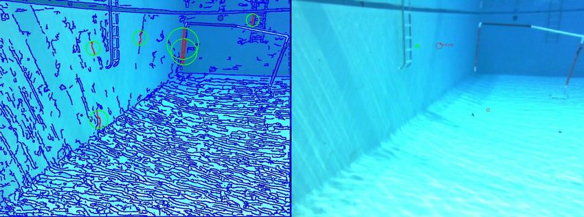
unique challenges, but a common thread is that each solution         Due to the remote work enforced COVID-19, the mechan-
was creative in their approach while still relying on tried and   ical team made the transition from our typical design method
true engineering principles.                                      of iterating using rapid prototyping techniques to a more
                                                                  analytical approach. This approach utilized more software
A. Mechanical                                                     simulation to finalize a design before we attempted to have it
   The focus for the mechanical design of SW8 was on creating     manufactured. Some of these new methods included structural
a robust platform that would allow new systems to be tested       and fluid simulations in SolidWorks, as well as mathematical
and implemented in the future, without having to rework the       optimization utilizing Matlab.
basic structure of the robot. This was achieved by building a        Members of our subteam developed an application that
durable frame around the concept of modularity. With SW8’s        runs in Matlab used to simulate the torpedo task by taking
modular frame the robot can easily be outfitted with any new      different variables that can be obtained from CAD files in
or updated peripherals it needs to perform each year’s shifting   SolidWorks. Using this app, we were able to spur new member
competition goals.                                                involvement by hosting our own miniature design competition.
   The physical structure of SW8 consists of powder coated,       New members created their own torpedo design, using the
aluminum frame sections held together by 3D printed joints        app to simulate their results. We then 3D printed all of the
and stainless fasteners. The aluminum frame is an improve-        new torpedoes and launched them in a pool to test how the
ment on Seawolf VII’s (SW7) design, as the acrylic frame          simulated performance compared to real world testing. The
of SW7 was fragile and led to many mechanical issues. In          best design is the one we will be using for the competition
comparison, SW8’s design provides structural integrity and        until another rises to take its place.
prevents external forces from acting on the electronics hull
where possible. We have also updated our thruster configura-      B. Software
tion to improve performance. The octagonal shape of SW8              To ensure our software system was able to complete ar-
facilitates an 8-thruster configuration which provides more       bitrary tasks whilst utilizing our hardware and open-source
stable attitude and strafe control, allowing for finer control    tools, we integrated the Robot Operating System (ROS) into
of the robot by the onboard computer.                             our architecture [1]. The software architecture of SW8 is struc-
                                                                  tured such that it enables communication between peripheral
                                                                  interfaces, controllers, sensing, and the robot’s mission nodes.
                                                                  The structure of our software system also allows for changes
                                                                  to our electronic system without significant changes to our
                                                                  software.

                 Fig. 1. Solidwords render of SW8

                                                                                  Fig. 3. SW8’s Software Architecture

                                                                     Our inability to perform underwater tests due to the restric-
                                                                  tions of the pandemic forced us to come up with new creative
                                                                  solutions to continue writing new software. The biggest of
                                                                  these improvements was the development of a simulation
                                                                  environment that allows code to be tested without the real
                                                                  robot. The simulation environment has a version of SW8
                                                                  which is able to move in the same ways as the physical
                                                                  robot and has the same collection of sensors. Importantly, this
                                                                  simulated version of the robot interfaces with the software in
                                                                  the same way that the real robot does. This is critical to ensure
                                                                  that software does not have to be modified in order to work
                      Fig. 2. Picture of SW8                      in simulation.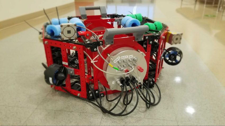
One issue we had to address while making our simulation        to play a crucial role in the system. To achieve this goal, we
system was the level of detail needed to perform testing. In      utilized a combination of off-the-shelf components to control
some instances, we wanted a more fine grain resolution, while     the robot and carry or switch power, as well as in-house
in other situations extra detail was unnecessary. For example,    designed custom electronics to manage the flow of current
the code which handles the movement of the robot relies on        and switch thrusters.
our flight controller, a Pixhawk. We could either simulate the       An example of this principle is the use of a Pixhawk flight
Pixhawk and the MAVLink connection between the Pixhawk            controller in SW8’s system design. The previous design relied
and our main computer, or we could have chosen to assume          on custom electronics that proved unstable and resulted in
the Pixhawk will always output our desired behavior. Our team     roadblocks for the entire team. By using a Pixhawk, the team
decided to tackle this issue by allowing users to select the      was able to leverage a stable electrical system to develop
level of detail they want the simulation to use. If we were       software and acoustics systems further than the previous
testing movement aspects of the software, we would enable the     iteration of Seawolf.
Pixhawk simulation, but if we were testing unrelated parts of        1) Load Balancing Board
the robot we can disable this to make the simulation experience      2) Opto-Isolator Board
smoother and less computationally intensive.                         3) Main Electronics Board
   Another issue our team faced was that not all our members         These devices tie the rest of the system together, and can
had the ability to run the demanding simulation software          be seen highlighted in yellow within the block-diagram of our
we had developed. To solve this problem the team looked           system in Fig 5.
towards a software industry standard that we believed could
be applied to robotics. We implemented a form of continuous
integration (CI) into our software engineering process, which
allowed developers to test their code in a remote simulator. We
utilized Github Actions to seamlessly integrate these simulator
tests into our preexisting version control system. This system
allowed us to run a series of tests each time a commit was
pushed into our Github repository.
   The tests themselves were also an engineering challenge.
The simulator software (Gazebo) does not have a standardized
way to create tests [2]. In order to implement our CI system
we had to create a custom plugin for Gazebo that allowed
us to write extensive behavior testing for the robot. These
tests allowed us to visually place goals in a test environment
that helped to track the robots progress in a quantitative way.                 Fig. 5. Electronics system block diagram
This allowed us to easily create a wide variety of tests for
the different RoboSub challenges. Then, when the simulation          The Load Balancing Board is designed to draw current
was run without any graphical display in the remote server, it    proportionally from two lithium polymer batteries safely,
was still possible to see how the robot was doing by tracking     discharging both at the same rate. This design has allowed
its progress through these placed goals. This also allowed us     SW8 to move from one large battery to two smaller batteries
to see a nice report of how the test went without having to       which can be separately housed and fused. If need be, this
watch the entire simulation play out. We found this tool to be    design could be expanded to balance more than two batteries.
so useful that the team is working on creating a public version      The Opto-isolator Board solves a unique problem encoun-
of the tool so other Gazebo users can create similar tests.       tered during the testing phase of initial designs. When low-
                                                                  side switching thrusters in the killswitch system, a problem
                                                                  arises wherein the ground connection is kept alive through
                                                                  the ESC signal ground cables. By optically isolating battery
                                                                  ground from thruster ground with the custom PCB, SW8 can
                                                                  be low-side switched using a power MOSFET and gate driver
                                                                  without the need for a more complicated or expensive high-
                                                                  side switching setup.
                                                                     The Main Electronics Board uses an MSP430 Launchpad
                                                                  to switch thruster power by controlling a low-side MOSFET.
                   Fig. 4. SW8 gate simulation
                                                                  Power to the other electronics, such as the onboard computer
                                                                  and Pixhawk, is switched by controlling a high-side solid
C. Electrical                                                     state relay (SSR). This setup gives command of our entire
  The electrical design of SW8 was kept as straightforward        electrical system to a programmable control board, which can
and robust as possible, while still allowing for unique designs   be customized and expanded upon as needed. As core parts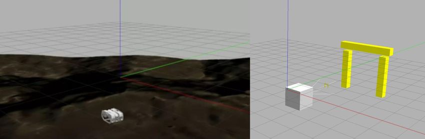
of our system are proven over time, the Main Electronics restrictions required strictly virtual meetings and enforced very
Board will define how we replace off-the-shelf components limited lab access.
with customized designs. When possible, effort was placed on implementing these
system changes and performing bring-up testing so that SW8
D. Acoustics would be pool-test ready come the spring. It was also during
For the most stable and accurate signal filtering, a band pass this time that design work was able to be focused over onto
filter is used for each channel to ensure all noise is removed. testing. Once spring arrived, the focus then shifted to testing
Active high and low pass filters were built using a combination changes and designs brought in over the fall. We aimed for one
of hand built circuits and monolithic integrated circuits (IC’s). pooltest per month, which would allow us to make meaningful
The high pass filter element was completely hand built as we adjustments or progress between each test but still get in the
only need a single cutoff frequency to ensure removal of low water frequently enough to see results and adjust goals if need
frequency noise. The low pass filter side of the circuit utilizes be.
an IC that gives us the ability to program the cutoff frequency
and change the frequency response of our system. Having A. Mechanical
the ability to change the low-pass cutoff enables us to use
One aspect tested during some pool tests was the per-
a variety of pinger frequencies in the event some frequencies
formance of various torpedo designs. The torpedoes are 3D
work better than others.
printed components, which allows for rapid prototyping and
It was determined that having a single power supply would
acts as an easy method of comparison between designs.
be the most efficient way to run the acoustics system. To avoid
These designs included variations to factors such as geometry,
losing half of our signal this meant a new signal needed to
material, and print orientation in order to optimize the distance
be created “Analog Ground” that would be set to 4.5 volts
traveled and minimize the amount of stray from launch. In
and would act as relative 0 for our signals. Since all signals
addition, a MATLAB script and GUI were developed to
come in biased at 0 volts, this meant a buffering and biasing
provide theoretical results of torpedo designs before obtaining
circuit needed to be incorporated such that the signal’s relative
actual results from pool tests for comparison.
ground would be 4.5 volts.
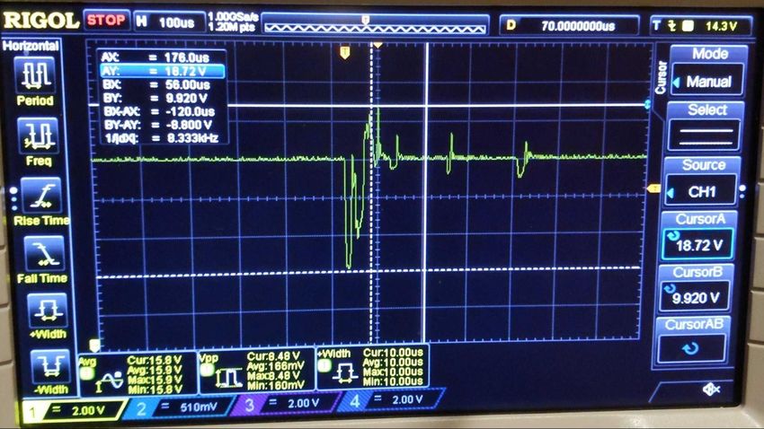
After biasing and amplifying, the signal is then sent through
an on board oscilloscope to log data. Utilizing an oscilloscope
gives us the ability to quickly and accurately log our signal
data without needing to develop complex software to do it
ourselves. Data can easily be collected and sent directly to a
computer with signal fidelity that would be hard to achieve
without the on board oscilloscope.
After the signals are captured, software algorithms are
used to process the data and determine the location of the
pinger. The Acoustics team utilizes the Python programming
language, as it combines power with ease of use and learning.
Python is powerful enough to perform the necessary com-
putation to determine pinger locations, as there are several
pre-existing packages that have been tried and tested such as
NumPy which make performing the math much more simple Fig. 6. Solidworks rendering of torpedo design
[3].
III. E XPERIMENTAL R ESULTS
During the 2020-2021 academic year, the club conducted
a total of six pool tests, with roughly a month between tests.
Each pool test acted as performance evaluation of SW8’s sys-
tems that were developed and tuned throughout the preceding
month. Because we were unable to bring many members to
our pool tests, due to COVID-19 restrictions, we began live
streaming our Pool tests on Twitch. The decision to livestream
our pool tests also increased member involvement over the past
year because remote team members were able to tune in and
interact live with those at the test.
Because major changes to the electrical and software sys-
tems were required during the fall semester, no pool tests Fig. 7. MATLAB GUI for torpedo testing
were possible until the spring. During this time, Covid-19B. Electrical system for controlling movement was not immediately created,
The electrical team began testing an upgraded electrical the team rapidly prototyped different control inputs until we
system, which included changes to the power system, moth- arrived at this solution. This rapid iteration and development
erboard, and power/thruster switching. Because of the large would not have been possible without the extensive use of our
amount of changes affecting power, in-depth testing was software simulator to see what was most effective in a very
performed on the system using an oscilloscope as seen in Fig short period of time. When tested in the pool, our final system
8. It was found that, though the drop in voltage due to inrush worked as desired and was robust for many types of movement
current to capacitors downstream was significant, it was not goals.
show-stopping. Unfortunately, while testing the robot’s movement we found
an issue that could not be caught in simulation and needed
real world testing. This involved the communication link
between our thruster control system, the Pixhawk, and our
main onboard computer. These components communicated
using the MAVLink protocol. Even in our more fine grain
software-in-the-loop simulations our configuration of this link
seemed to work. However, when tested in the pool, we found
many configuration issues that were particular to our physical
system. We spent much of our first few pool tests fixing these
configuration issues until we achieved similar performance in
both simulation and practice.
Another system that needed real world testing was our
computer vision software. This year we focused on writing
gate detection code first and foremost. It is difficult to produce
Fig. 8. Noise from inrush current reliable simulated computer vision targets, so the team chose
to rely on pool tests to collect videos which would serve
Further testing of this system took place once the robot was as training datasets for later testing. We also augmented our
able to reach the water in the spring. A new three-position dataset using footage collected at past RoboSub competitions.
power switch to allow on/off action from outside the hull and Upon running the programs on live targets in a pool, we found
a new method of switching thrusters were among the main that it was not reliably detecting the gate, and many times was
goals for our first pool test. To ensure our power and thruster overwhelmed by the number of reflections in our particular
switching was working properly, the behavior of these systems pool.
was closely monitored for any sign of misbehavior at each pool
test held during the spring.
During one of our latest tests, the killswitch failed to reliably
kill power to thrusters. The robot was software killed and
powered off, and it was later discovered that the MOSFET
used to switch thrusters was internally destroyed. Investigation
into transient voltages into the device showed nothing out of
the ordinary. Physical damage to the device was discovered,
but because the damage was delivered to the device during the
fall and the component had only recently failed, the results
Fig. 9. Implementation of computer vision code
remain inconclusive. A replacement was issued and is being
monitored for any similar internal damages between pool tests. This has caused us to go back to the drawing board for
C. Software our computer vision code and rethink a new approach to our
algorithms to make them more robust in environments with
Software systems were tested during every pool test and problematic reflections.
many adjustments were made after collecting experimental
results. Before each pool test, the software team would create D. Acoustics
a plan of what should be tested in the pool, and then run these The acoustics team conducted controlled testing of our
tests in our simulation system. The first major software system filtering circuits to ensure proper amplification occurred with
to be tested was our movement control system. One aspect of desired signals and proper attenuation occurred with undesired
this system that benefited from the simulation testing was the signals. In the course of our testing the following bode plot
type of input given. Our movement input to the robot consists was obtained, indicating lower cutoff frequency of 6.84 kHz
of a 2D vector for the desired planar velocity of the robot, and a higher cutoff frequency of 36.95 kHz.
a scalar that gives the true desired depth of the robot and These cutoff frequencies encompass a range of pinger fre-
a quaternion that defines the desired angle of the robot. This quencies we are allowed to use at competition, indicating our[3] C. R. Harris, K. J. Millman, S. J. van der Walt, R. Gommers,
P. Virtanen, D. Cournapeau, E. Wieser, J. Taylor, S. Berg, N. J.
Smith, R. Kern, M. Picus, S. Hoyer, M. H. van Kerkwijk, M. Brett,
A. Haldane, J. F. del Rı́o, M. Wiebe, P. Peterson, P. Gérard-Marchant,
K. Sheppard, T. Reddy, W. Weckesser, H. Abbasi, C. Gohlke,
and T. E. Oliphant, “Array programming with NumPy,” Nature,
vol. 585, no. 7825, pp. 357–362, Sep. 2020. [Online]. Available:
https://doi.org/10.1038/s41586-020-2649-2
[4] G. Bradski, “The OpenCV Library,” Dr. Dobb’s Journal of Software Tools,
2000.
A PPENDIX A
C OMPONENET S PECIFICATIONS
Fig. 10. Bode plot of filtering circuits
filtering circuit is viable. In addition, for Low Pass Filtering,
an LTC1564 IC is used giving us the ability to adjust the cutoff
frequency so that if 40 kHz is used, it falls within our filtering
band.
The acoustics team also successfully integrated a new Pi-
coTech picoscope to our system. In our work it was necessary
to be able to capture a signal, run it through our filtering
circuits and log the data using the picoscope controlled by
a raspberry pi. Since the raspberry pi must be underwater
with the picoscope and the rest of the acoustics system, it
was necessary to remotely connect to the raspberry pi and run
code from the terminal to capture data. To accomplish this, we
utilized PicoTech’s SDK and drivers and adapted pre-existing
Python scripts such that we could capture data while operating
the raspberry pi headlessly over SSH. We were successfully
able to take a signal, run it through our filtering circuits, and
capture the data with our picoscope using Python scripts, all
while remotely connected to the system via SSH.
This is the first step towards being able to integrate the
acoustics system with the robot as since we have proven
we can capture data, all that is necessary is to perform
the mathematical analysis of the signal and return a pinger
location.
IV. ACKNOWLEDGEMENTS
The Underwater Robotics Club is housed within North Car-
olina State University’s Electrical and Computer Engineering
department. We would like to thank the faculty and staff
who have supported and continue to support the club. Special
thanks to Dr. John Muth and Dr. John-Paul Ore for advising
the club, as well as Carmichael Gymnasium for providing us
a facility for testing. Lastly, we would like to extend our
gratitude to our sponsors for providing us access to their
technical products for helping design and develop the robot.
R EFERENCES
[1] M. Quigley, K. Conley, B. Gerkey, J. Faust, T. Foote, J. Leibs, R. Wheeler,
and A. Ng, “Ros: an open-source robot operating system,” vol. 3, 01 2009.
[2] N. Koenig and A. Howard, “Design and use paradigms for gazebo, an
open-source multi-robot simulator,” in IEEE/RSJ International Confer-
ence on Intelligent Robots and Systems, Sendai, Japan, Sep 2004, pp.
2149–2154.Component Vendor Model/Type Specs Cost (if new) Status
Frame Self Custom 0.25 in 6061-alloy alu- Integrated
minum and 3D printed
PLA parts
Waterproof Housing Self Custom Custom aluminum end Integrated
caps with double o-
ring seals
Waterproof Fischer Connectors 103, 104, 105 series IP68 Integrated
Connectors
Cable Penetrators Blue Robotics M10 950 meter depth rating $5.00 Integrated
Flight Controller mRo Pixhawk 3-axis gyroscope, Integrated
3-axis accelerom-
eter/magnetometer,
3-axis accelerom-
eter/gyroscope,
barometer
Battery Turnigy 16000 mAh 12-24 C $246.00 Integrated
Battery Turnigy 5000 mAh 30-40 C $66.00 Purchased
Solid State Relay Crydom DC100D100C 100 A, 32 V $173.00 Integrated
Killswitch MOSFET IXYS IXTN660n04t4 N-Channel, 40 V, 660 $28.00 Integrated
A, Chassis Mount
Regulator EKYLIN K24053.5 Step down converter $13.00 Integrated
regulator 5 V, 5 A
Pixhawk Power Mod- Holybro PM02 V3 $18.00 Integrated
ule
CPU NVIDIA Jetson Nano $59.00 Integrated
Internal Communica- UART Integrated
tion Network
External Communica- Ethernet Integrated
tion Interface
Programming Python 2.7 & 3.X Integrated
Language 1
Programming C++ C++11 Integrated
Language 2
Camera 1 Microsoft Lifecam Integrated
Camera 2 Intel Realsense D435i RGBD $208.00 Purchased
Hydrophones Aquarian Audio H2A Hydrophone Purchased
Algorithms: Vision Opencv [4] 4.2 Integrated
Algorithms: Acoustics Numpy [3] 1.21 Integrated
Algorithms: ROS [1] Noetic Integrated
Autonomy
Open Source Software Opencv, Python, Integrated
Linux, ROS,
PicoTech, Gazebo
[2]
Oscilloscope Pico Technology Picoscope 4824 80 MS/s $2,300.00 PurchasedYou can also read